EP2740895A2 - Capteur de distance de cuvelage pour tunnelier - Google Patents
Capteur de distance de cuvelage pour tunnelier Download PDFInfo
- Publication number
- EP2740895A2 EP2740895A2 EP13196094.0A EP13196094A EP2740895A2 EP 2740895 A2 EP2740895 A2 EP 2740895A2 EP 13196094 A EP13196094 A EP 13196094A EP 2740895 A2 EP2740895 A2 EP 2740895A2
- Authority
- EP
- European Patent Office
- Prior art keywords
- shield
- sensor
- boring machine
- tunnel boring
- shield tube
- Prior art date
- Legal status (The legal status is an assumption and is not a legal conclusion. Google has not performed a legal analysis and makes no representation as to the accuracy of the status listed.)
- Withdrawn
Links
- 239000000463 material Substances 0.000 claims abstract description 10
- 238000002604 ultrasonography Methods 0.000 claims description 40
- 230000005670 electromagnetic radiation Effects 0.000 claims description 26
- 239000011435 rock Substances 0.000 claims description 19
- 210000005239 tubule Anatomy 0.000 claims description 11
- 238000011156 evaluation Methods 0.000 claims description 10
- 238000000034 method Methods 0.000 claims description 9
- 238000005553 drilling Methods 0.000 claims description 5
- 230000005855 radiation Effects 0.000 claims description 5
- 244000208734 Pisonia aculeata Species 0.000 claims 1
- 238000005259 measurement Methods 0.000 description 11
- 229910000831 Steel Inorganic materials 0.000 description 6
- 230000006378 damage Effects 0.000 description 6
- 239000010959 steel Substances 0.000 description 6
- 239000000945 filler Substances 0.000 description 5
- 238000004364 calculation method Methods 0.000 description 3
- 239000004568 cement Substances 0.000 description 3
- 238000010276 construction Methods 0.000 description 3
- 238000011109 contamination Methods 0.000 description 3
- 238000001514 detection method Methods 0.000 description 3
- 230000003287 optical effect Effects 0.000 description 3
- 230000001427 coherent effect Effects 0.000 description 2
- 230000001276 controlling effect Effects 0.000 description 2
- 238000013461 design Methods 0.000 description 2
- 230000001953 sensory effect Effects 0.000 description 2
- 238000013459 approach Methods 0.000 description 1
- 238000004140 cleaning Methods 0.000 description 1
- 230000002596 correlated effect Effects 0.000 description 1
- 230000000875 corresponding effect Effects 0.000 description 1
- 230000007547 defect Effects 0.000 description 1
- 230000001419 dependent effect Effects 0.000 description 1
- 230000000694 effects Effects 0.000 description 1
- 230000005611 electricity Effects 0.000 description 1
- 230000007613 environmental effect Effects 0.000 description 1
- 239000011798 excavation material Substances 0.000 description 1
- 238000009434 installation Methods 0.000 description 1
- 230000010354 integration Effects 0.000 description 1
- 230000003993 interaction Effects 0.000 description 1
- 239000007788 liquid Substances 0.000 description 1
- 230000002093 peripheral effect Effects 0.000 description 1
- 230000001681 protective effect Effects 0.000 description 1
- 230000008054 signal transmission Effects 0.000 description 1
- 239000002689 soil Substances 0.000 description 1
- 230000006641 stabilisation Effects 0.000 description 1
- 238000011105 stabilization Methods 0.000 description 1
- 230000001960 triggered effect Effects 0.000 description 1
- 238000009423 ventilation Methods 0.000 description 1
- XLYOFNOQVPJJNP-UHFFFAOYSA-N water Substances O XLYOFNOQVPJJNP-UHFFFAOYSA-N 0.000 description 1
Images


Classifications
-
- E—FIXED CONSTRUCTIONS
- E21—EARTH OR ROCK DRILLING; MINING
- E21D—SHAFTS; TUNNELS; GALLERIES; LARGE UNDERGROUND CHAMBERS
- E21D9/00—Tunnels or galleries, with or without linings; Methods or apparatus for making thereof; Layout of tunnels or galleries
- E21D9/003—Arrangement of measuring or indicating devices for use during driving of tunnels, e.g. for guiding machines
-
- E—FIXED CONSTRUCTIONS
- E21—EARTH OR ROCK DRILLING; MINING
- E21D—SHAFTS; TUNNELS; GALLERIES; LARGE UNDERGROUND CHAMBERS
- E21D11/00—Lining tunnels, galleries or other underground cavities, e.g. large underground chambers; Linings therefor; Making such linings in situ, e.g. by assembling
- E21D11/40—Devices or apparatus specially adapted for handling or placing units of linings or supporting units for tunnels or galleries
- E21D11/403—Devices or apparatus specially adapted for handling or placing units of linings or supporting units for tunnels or galleries combined with the head machine
-
- E—FIXED CONSTRUCTIONS
- E21—EARTH OR ROCK DRILLING; MINING
- E21D—SHAFTS; TUNNELS; GALLERIES; LARGE UNDERGROUND CHAMBERS
- E21D9/00—Tunnels or galleries, with or without linings; Methods or apparatus for making thereof; Layout of tunnels or galleries
- E21D9/06—Making by using a driving shield, i.e. advanced by pushing means bearing against the already placed lining
- E21D9/0607—Making by using a driving shield, i.e. advanced by pushing means bearing against the already placed lining the shield being provided with devices for lining the tunnel, e.g. shuttering
Definitions
- the invention relates to a shield for a tunnel boring machine for drilling a borehole in a mountain range, a method for controlling the lining of a borehole wall of a borehole to be drilled by means of a tunnel boring machine with tubbing and a tunnel boring machine.
- a tunnel boring machine is a machine used to build tunnels.
- Components of a tunnel boring machine include a demolition screen with feeding and bracing devices, facilities for the installation of support and extension measures, equipment for material removal, a supply unit (electricity, compressed air, ventilation, water), and transport equipment for excavation material, proppant and finishing materials.
- a gripper presses or tightens against the rock that forms the borehole wall of an already partially drilled wellbore section and thereby supports the tunnel boring machine against the mountain.
- the tension of the gripper is released against the mountains, and the catch is tracked with respect to the advanced drill head.
- the borehole is circumferentially lined according to Bohrfort suits by segments, the axial and radial together create an annular stabilization of the borehole.
- the next Tübbingen set can either be placed on the borehole wall during a stroke or after completion of a stroke.
- a mostly metallic tube for example made of steel
- the rear end of the shield is called a tail shield.
- the shield serves to protect components of the tunnel boring machine from possibly collapsing rock and is interposed between the mountains and a soon to be laid tubbing. It is important that the distance between the tubing and the shield tube, which distance is also called tail tail air, must not be too low, in particular may not be zero. If this happens, the tubbing can be damaged by the shield tube. In an extreme case, the tunnel boring machine can even get stuck completely. This can or even prevent the work during a lifetime of the tunnel boring machine in the order of days or weeks.
- this distance is measured manually.
- a polisher for example, walks around the circumference of the shield tube with a folding rule at four positions and measures the distance.
- this method is prone to error, consuming and dangerous for the polisher.
- the company VMT offers the so-called "Automatic Tail Skin Clearance Measurement System SluM", with which such distances can be sensed.
- Several lasers are arranged in the draw, which measure the distance between the tubing and the wall at several points by means of a laser distance measurement.
- the construction of the laser distance measuring devices in the area of the catchment and the Laying of the segments is hindered because in this area the erector works, which moves the segments. Also in this area the risk of destruction for the sensitive laser is considerable.
- Another disadvantage of this system is that first the distance between the shield tube and the borehole wall is measured and only then the segments are measured. Sometimes a time of a few minutes passes between these two partial measurements, so that a comparison of the two measurement results is only possible to a limited extent and sometimes the accuracy of the measurement is insufficient.
- a shield for a tunnel boring machine for boring a borehole in a mountain having a shield tube for protecting a portion (particularly components) of the tunnel boring machine from rock wall dissolving rock material, the shield pipe temporarily between a tubing to be laid (ie, a tubing not yet attached to the wellbore wall but to be secured there soon) for lining the borehole wall on the one hand and the borehole wall (ie, the boundary wall between the mountain and the already drilled part of the borehole) on the other is to be arranged.
- the shield further comprises at least one arranged on and / or in the shield tube (in particular attached to the shield tube) sensor for detecting an indicative of a distance between the shield tube and the tubing to be laid information (for example, a sensor signal, from alone or in combination with other, measured and / or known data, the distance can be determined by calculation) on.
- a sensor signal for example, a sensor signal, from alone or in combination with other, measured and / or known data, the distance can be determined by calculation
- a tunnel boring machine for drilling a borehole in a rock, the tunnel boring machine having a shield with the features mentioned above.
- a method of controlling the lining of a borehole wall with a tubing to be drilled by a tunnel boring machine including placing a shield tube of a shield of the tunnel boring machine between a tubbing to be laid and a borehole wall in order to protect a section (in particular components) of the tunnel boring machine from rock material loosening from the borehole wall, and an information indicative of a distance between the shield tube and the tubing to be laid is detected by means of at least one sensor arranged on and / or in the shield tube, and the laying of the tubbing to be laid is controlled at the borehole wall based on the detected information.
- the minimum distance between a predetermined position or a predetermined surface area of the shield tube on the one hand and the tubbing to be laid on the other hand can be understood.
- this term can also be understood as meaning any other, predefined distance parameter in the ratio of shield tube tubbing.
- this may be the smallest distance of the tubbing from a surface of the shield tube.
- this may be the distance between the tubbing and a predetermined portion of the shield tube, for example its inner collar or its inner surface. It is also possible according to the invention to detect a plurality of distances between segments and different surface areas of the shield tube, for Example in several peripheral surface sections of the shield tube in order to obtain a further refined information base with regard to the circumferential distance distribution.
- a sensor for sensory acquisition of data which allow the determination of the distance between the shield tube and a tubbing to be laid, is preferably mounted or provided on the inner surface of the shield tube.
- This position of the sensor on the shield tube is insensitive to falling rock or the like, since the shield tube between tubing and borehole wall is located and the measurement between tubing and shield tube protected on the inner surface of the shield tube plays.
- the positioning of the sensor at this point does not interfere with the construction of the tunnel boring machine and thus allows a high-precision and fault-robust measurement.
- the integration of the sensor on or in the shield thus improves the operational reliability of the tunnel boring machine and allows a completely safe and high-precision detection of the distance between the next to be laid tubbing and the inner surface of the shield tube.
- the senor can be arranged on an inner lateral surface of the shield tube facing away from the borehole wall (for example, be fixedly mounted on it) and / or arranged in an inner lateral surface of the shield tube facing away from the borehole wall (for example integrated therein, for example on the Finish flush with the shield tube).
- the sensor is safely protected from the surrounding mountains, from tubbing and from components of the tunnel boring machine and is also capable of barrier-free detection of a tubbing arranged inside the shield tube.
- the shield tube may be an at least partially circumferential, in particular full-circumference, support ring one - with respect to a feed direction of the tunnel boring machine - have the rear end of the shield tube.
- the shield tube is provided with a support ring, which may also be formed of steel. This support ring forms, together with the rest of the shield tube, a protected or shielded space which remains free of other components, in particular of the tubbing to be handled.
- the position in a boundary region between the support ring and jacket of the shield tube provides an ideal pick-up position for the sensor.
- the support ring and a lateral surface of the shield tube may be integrally formed, in particular one-material.
- the support ring and the shield tube can be formed as parts welded together, for example made of steel.
- the support ring starting from a hollow cylindrical and open at the end of the lateral surface of the shield tube collar-shaped inwardly projecting.
- a right angle between the collar-shaped inwardly inverted supporting ring and the hollow cylindrical, in particular hollow cylindrical, shield tube formed. At this angle, advantageously, the sensor can be positioned without being exposed to the danger of destruction or damage.
- the senor may be arranged on and / or in an inner circumferential surface of the shield body facing away from the borehole wall adjacent to the support ring.
- the sensor may be mounted on the inner circumferential surface of the hollow cylindrical shield body in a range of less than 50 cm, in particular a range of less than 30 cm, away from the support ring, where the shielding protective effect of the support ring is particularly pronounced.
- the senor may be less protruding beyond the inner circumferential surface than the sensor Support ring. Then the projection of the support ring provides a particularly good mechanical protection of the mounted in the shadow space sensor.
- the senor may be arranged on a rear end of a shield tail of the shield tube in the feed direction of the tunnel boring machine. Close to this position there is a tubbing to be laid next, so that the placement of the sensor at the end of the shield tail allows for particularly accurate determination of the size of the shield tail air.
- the senor may be an ultrasonic sensor.
- An ultrasonic sensor is particularly well suited because it is flat in its design, inexpensive available and reliable in harsh or dirty atmosphere is used, as it prevails in a well.
- Such an ultrasonic sensor is based on emitting ultrasound waves from a known position and detecting them after interaction with the segment to be laid in the vicinity of the ultrasound sensor.
- An ultrasonic sensor according to the invention is particularly preferred because it is completely insensitive to contamination and the like.
- the senor may include an ultrasound source for generating and directing ultrasound to the tubule and having an ultrasound detector for detecting ultrasound reflected on the tubule.
- the ultrasound source and the ultrasound detector can be integrated in a compact unit and, together with an evaluation unit, can determine the distance of the tubbings from the inner surface of the shield tube by comparing the emitted ultrasound and the reflected ultrasound.
- the shield may have an ultrasonic deflection element between the ultrasound source and the ultrasound detector, on the one hand, and the tubbing, on the other hand, to deflect ultrasound from the ultrasound source to the tubule and from the tubule to the ultrasound detector.
- an ultrasonic deflection element can For example, a prism or a reflector mirror may be such that its surface directs ultrasonic waves coming from the ultrasonic generator onto the tubbing, and ultrasonic waves coming from the tubing faces the ultrasonic detector.
- the senor may be an electromagnetic radiation sensor.
- an ultrasonic sensor it is therefore also possible to use a radiation sensor which is based on the emission and detection of electromagnetic radiation, such as, for example, visible light, ultrasound, infrared or electromagnetic radiation of another suitable wavelength range.
- electromagnetic radiation sensors for example laser distance measuring devices, it must be ensured in the use according to the invention that contamination of corresponding components is avoided or that these components are cleaned again when contamination has occurred. The latter can be done manually or by means of an automatic cleaning system, for example a windscreen wiper system.
- the senor may comprise an electromagnetic radiation source for generating and directing electromagnetic radiation to the tubbing and having an electromagnetic radiation detector for detecting electromagnetic radiation reflected at the tubbing.
- the electromagnetic radiation source may be a laser source that emits coherent light in the direction of the tubbing. The laser light reflected from the tubbing can then be evaluated to determine the distance of the tubbings from the shield tube.
- the shield may further comprise an electromagnetic radiation deflecting element between the Have electromagnetic radiation source and the electromagnetic radiation detector on the one hand and the tubbing on the other hand to deflect electromagnetic radiation from the electromagnetic radiation source on the tubbing and of the tubbing on the electromagnetic radiation detector.
- Straight laser distance sensors often have a relatively large dimension, which can be mounted particularly easily in the cramped conditions in the boundary region of a shield tube and a collar-shaped support ring, when a radiation and reception direction of the laser light is made possible parallel to the feed direction.
- a deflection prism, a reflector mirror or the like such a relatively large laser distance measuring device can be used according to the invention.
- the shield may comprise a plurality of sensors (for example between three and ten, in particular seven) with the features described above, wherein the sensors are distributed along a circumference of the shield tube.
- the sensors can be arranged circumferentially around a feed axis. In this way it is possible to monitor the tailrace air around the entire shield tube.
- sensors arranged substantially on opposite sides of the shield tube can provide correlated distance information, since reducing the one distance requires the other, opposite distance to be increased. In this way, with a partly redundant measurement, the error robustness of the system can be further improved.
- a floor area of the shield tube which floor area is in contact with the mountain when used as intended, may be kept free of sensors.
- the area of the shield tube which is kept free of sensors may correspond to an angle range of ⁇ 60 °, in particular ⁇ 30 °, around the bottom-nearest point of the shield tube. This prevents sensors from passing through Contact with soil, liquid and other mountain material may be damaged or destroyed.
- the shield may include a filler transport line for providing a space between the tubbings and the borehole wall with filler, and a cable connection, in particular a steel sheathed cable connection, for forming an electrical connection between the sensor and a partner device, in particular a sensor signal evaluation unit for evaluating a signal of the sensor and / or an electrical energy supply unit for supplying the sensor with electrical energy, the feed-transport line and the cable connection next to each other preferably both being guided along an inner circumferential surface of the shield tube.
- Cement can be pumped into the annulus between the tubbing and the mountain via a feed transport line, for example a cement line, to fix the tubbing.
- an outer diameter of the shield tube may be in a range between about 2 m and about 15 m, in particular in a range between about 4 m and about 13 m.
- the shield according to the invention for tunnel boring machines of various sizes can be used.
- the tunnel boring machine may have an evaluation unit which is used to evaluate the Sensor signal detected by the sensor is set up to determine the distance between the shield tube and the tubbing to be laid.
- an evaluation unit may be a processor which determines the actual distance information from the raw measurement data.
- the evaluation unit may be configured to trigger a predetermined event if the determined distance falls below a predetermined threshold value.
- This threshold may be, for example, about 5 cm, in particular about 2 cm. In this way it can be avoided that the tail air is dangerously small. If it becomes zero, this may damage the segments, as the shield tube then scrapes along them. Also, this can lead to a sticking of the entire tunnel boring machine, which can result in significant downtime.
- the predetermined event may be turning off the tunnel boring machine, issuing a warning, and / or adjusting an operating parameter of the tunnel boring machine to increase the distance again.
- Other or more events can also be triggered if the tail tail air falls below a certain size or becomes zero.
- the tunnel boring machine may include a tubbing laying unit configured to control the lining of the borehole wall with tubbing based on the distance indicative information.
- the laying of the segments which may be formed as curved, substantially trapezoidal body is carried out according to predetermined rules or algorithms, in which a direction of the borehole to be drilled (left turn, right turn, slope, gradient or straight course), but also the current absolute position belongs to the segments to be laid or the relative position between Tübbingen and shield tube.
- Trapezoidal universal segments can be used to line all types of borehole directions.
- the laying process of the segments using an erector can be controlled in accordance with the invention to enter into this calculation the high-precision recorded sensor data, which can conclude the distance between the shield tube and tubbing to be laid.
- the tunnel boring machine may comprise a rotatable drill head at a front end of the tunnel boring machine, on which a plurality of cutting elements for removing the rock are arranged.
- the tunnel boring machine may further comprise a feed device, which has for exerting a feed force for advancing the drill head against the mountains.
- the tunnel boring machine may include a gripper configured to temporarily support the tunnel boring machine by means of bracing against the mountain (in a direction perpendicular to the direction of advance).
- the tunnel boring machine may include an erector configured to lay the tubbings along the borehole wall.
- the tunnel boring machine can have a rear-side pull arranged with respect to the feed direction, which has supply devices for supplying the tunnel boring machine.
- a front shield position can first be determined using a camera measuring system.
- a camera measuring system By means of a theodolite system the positioning of a gripper shield can be determined. This allows a georeferenced calibration of front shield and Gripper shield. Orientation information can also be determined by means of a two-axis inclination sensor measurement in the horizontal and vertical measuring direction.
- the position of front shield and Gripperschild are always known.
- the geometry of the excavated cavity or borehole is known. The lining of the borehole wall with tubbing should now follow the shield axis, otherwise the shield tail air approaches zero and the segments may be damaged.
- the information is still required, such as the tubbing oriented relative to the shield tail to perform a correct control.
- the distance measurement according to the invention between the segments to be laid and the shield tube it is possible to control how the segments are to be laid.
- the lining of the borehole wall is controlled by tubbing, wherein the sensor signal serves as an input parameter for the calculation of the tubbing lining.
- Fig. 1 10 shows a cross-section through a wellbore 104 drilled in a rock 102 by means of a tunnel boring machine 100 according to an exemplary embodiment of the invention.
- Fig. 1 shows the tunnel boring machine 100 at the beginning of a working stroke, during which a drill head 106 of the tunnel boring machine 100 forward, that is according to Fig. 1 to the left, working into the mountains 102 while removing rocks of the mountains 102, forming a successively increasing borehole 104.
- a gripper 110 is shown, which in accordance with Fig. 1 wedging vertical direction against the mountains 102 or to temporarily anchor a portion of the tunnel boring machine 100 at this position.
- a feed cylinder 108 which is driven by electric motors 120, presses the drill head 106 according to Fig. 1 to the left in the advancing direction, so that cutting elements on a front wall of the drill head 106 in a manner known to those skilled ablate the material of the mountain 102 while drilling the borehole 102 progressively.
- a stroke of the tunnel boring machine 100 for example of the order of 1 m to 2 m, corresponds to a dimension across which pistons of the feed cylinder 108 can be extended to drive the drill head 106 forward.
- the drill head has 106 of the catchment of the tunnel boring machine 100, that is the according to Fig. 1 Right-hand part of the tunnel boring machine 100, removed and the feed cylinder 108 has reached its maximum expansion position.
- the feed cylinder 108 In this operating state, the feed cylinder 108 must be returned to its original position and the retraction of the tunnel boring machine 100 must be tracked before a next stroke of the tunnel boring machine 100 can be performed.
- the tension of the gripper 110 against the surrounding rock 102 must first be solved. Then, when the feed cylinder 108 has reached its maximum expansion position (as in FIG Fig. 2 shown), the feed cylinder 108 and all according to Fig. 1 and Fig. 2 of which components provided on the right are tracked to the left.
- the segments 112 may be considered to be substantially trapezoidal but slightly curved bodies which are circumferentially placed around the substantially circular bore 104 on the borehole wall and fastened there with filler.
- Tübbing 112 is the tubbing that is currently being prepared for lining the borehole wall or is used. The actual lining and handling of the segments 112 takes place by means of an erector 120.
- a shield tube 118 of a shield protects the gripper 110, the erector 120 and other components of the tunnel boring machine 100 from undesirable environmental influences. Such undesirable influences include the falling loose rock of rock 102 at the edge of the borehole wall.
- the hollow cylinder made of steel, which forms the shield tube 118 covers all sides protecting the components of the tunnel boring machine 100, which surrounds it.
- Tubules 112 to be subsequently placed are positioned within the shield tube 118 prior to handling by the erector 120. In other words, the shield tube 118 is located in this operating state between the borehole wall on the one hand and the tubbing segments 112 to be laid subsequently.
- Fig. 1 Shown also schematically is a support ring 122 of the shield tube 118, which is located at a rear end of the shield tube 118 relative to the direction of advance.
- the support ring 122 is, although in Fig. 1 and Fig. 2 can not be seen, as an inwardly extending, annular disc-shaped collar formed which is angled at right angles to the otherwise hollow cylindrical tube wall of the shield tube 118 and forms the end of the shield also referred to as tail shield.
- At least one sensor 116 mounted on an inner circumferential surface of the shield tube 118 to measure from there the respective distance between the shield tube 118 and the tubbing 112 to be laid.
- Different configurations of the sensor 116 and different forms of mounting will be discussed below Fig. 4 to Fig. 7 explained in more detail with reference to exemplary embodiments.
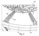
- Fig. 3 but first shows a view 300 of the interior of the present invention equipped with a sensor 116 shield tube 118 on the tail shield. Also, the end-side collar which forms the support ring 122 is in Fig. 3 to recognize. Other components of the tunnel boring machine 100 inside the shield tube 118 are in Fig. 3 also shown are not described in detail for the sake of brevity.
- Fig. 3 It is also in Fig. 3 have shown that two backfill transport lines 304 extend along an inner circumferential surface in the axial direction. These backfill transport conduits 304 serve to supply backfill between the borehole wall and tubbing to immobilize the tubbings on the borehole wall.
- the sensor 116 for detecting the distance between the shield tube 118 and the tubbing 112 to be laid (not shown in FIG Fig. 3 ) is attached to a boundary between the support ring 122 and the inner surface of the hollow cylindrical portion of the shield tube 118.
- the sensor 116 for example an ultrasonic sensor, requires power for operation, which is supplied via a power line 302.
- the power line 302 is arranged to run parallel to the feedstock supply lines 304 and is in close proximity so that any obstruction to building activity associated with the provision of the lines 302, 304 is minimized.
- the line 302 may be for transmitting electrical sensor signals from the sensor 116 to an in Fig. 3 Not shown Tübbingverlege Kunststoffmaschinemaschine serve.
- This uses, inter alia, the sensor information of the sensor 116, to control the laying of the segments.
- exact knowledge of the position of the segments is required as well as further geometry information (for example the position of Gripperschild and front shield, which can be determined using camera measuring systems or theodolites).
- the person skilled in the art is aware of how such a control of the laying of the segments is to be made.
- the sensor information can be supplied with high precision and with a very robust defect. In the dirty atmosphere of a borehole, a sensor 116 located inside the shield tube 118 can be operated well protected. Also, due to the collar-shaped everting of the support ring 122, a mechanical protection of the sensor 116 is given.
- Fig. 4 now shows a cross-sectional view of a shield 400 of a tunnel boring machine 100, which is formed by the shield tube 118 with its end-side annular disc as a support ring 122.
- An arrow in Fig. 4 indicates the direction of advance of the tunnel boring machine 100, that is, the direction along which a boring head 106 (not shown in FIG Fig. 4 ) prepares successively in the mountains 102.
- the support ring 122 runs fully around the hollow circular cylindrical portion of the shield tube 118th
- Fig. 4 schematically shows a plurality of segments 112, 114.
- Tubuli 112 are currently being laid and are in the operating state shown at a respective distance from the inner surface of the shield tube 118.
- Tubbing 112 shown above the distance is denoted by d.
- an ultrasonic sensor 116 is placed on the inner circumferential surface of the shield tube 118 and fixed there immovably.
- the ultrasonic sensor 116 includes an ultrasonic source for emitting primary ultrasound 402 on the tubbing 112 to be laid. Secondary ultrasound 404, which is reflected on the tubule 112, is detected by an ultrasound detector of the ultrasound sensor 116. From the recorded Sensor signal, the ultrasonic sensor 116 determine the distance to the tubbing to be laid 112 (in particular the distance relative to a predetermined reference position, for example, the position of the ultrasonic sensor 116 or the inner surface of the shield tube 118).
- the support ring 122 serves to shield the sensor 116 against undesired influences of the environment and as mechanical protection of the sensor 116 against damage.
- Fig. 4 further shows a supply and signal transport cable 302 extending axially from an ultrasonic sensor 116 along an inner surface of the shield tube 118.
- the cable 302 may be steel clad to accommodate the harsh conditions in the working area of a tunnel boring machine 100.
- the supply and signal transmission cable 302 supplies the ultrasonic sensor on the one hand with electrical energy.
- the ultrasonic sensor transmits the detected sensor information via the supply and signal transport cable 302 to an evaluation device (not shown).
- Fig. 5 shows schematically and in cross-section only a lower portion of a shield tube 118 of a shield 400 according to another exemplary embodiment of the invention.
- a laser distance meter 116 is provided as a sensor.
- the laser distance meter 116 emits coherent monochromatic laser light 502 in FIG Fig. 5 horizontal direction.
- This primary laser light 502 is deflected by an optical prism 500 by 90 ° onto the tubbing 112, reflected therefrom, and in turn passes via the optical prism 500 in the form of secondary radiation 504 to a photosensitive element of the laser distance meter 116.
- the configuration with the prism 500 allows It is to use in a particularly cramped environment laser measuring devices 116, as they can be clearly mounted with its flat, large-scale side on the inside of the shield tube 118 and can emit in the horizontal direction, the primary laser light 502.
- Fig. 6 corresponds to the embodiment of Fig. 4 , wherein the ultrasonic sensor 116 is now integrated into the interior of the shield tube 118, so that its surface is flush with an inner circumferential surface of the shield tube 118 or aligned. As a result, the ultrasonic sensor 116 is particularly well protected against mechanical influences of the environment.
- FIG. 12 shows a shield 400 according to yet another exemplary embodiment of the invention, in which the sensor 116 is integrated into the support ring 122, whereas an ultrasound reflection prism 700 is attached to an inner surface of the shield tube 118.
- the primary ultrasound radiation 402 is emitted by the sensor 116, reflected on the ultrasound reflection prism 700 upwards in the direction of the tubing 112 to be laid and, after reflection on the latter and after repeated reflection on the ultrasound reflection prism 700, arrives at an ultrasound detector of the ultrasound sensor 116.
- the ultrasonic sensor 116 need not necessarily be integrated into the support ring 122, but may also be placed on this projecting. In both cases, the support ring 122 serves as protection against mechanical damage.
Landscapes
- Engineering & Computer Science (AREA)
- Mining & Mineral Resources (AREA)
- Life Sciences & Earth Sciences (AREA)
- General Life Sciences & Earth Sciences (AREA)
- Geochemistry & Mineralogy (AREA)
- Geology (AREA)
- Environmental & Geological Engineering (AREA)
- Architecture (AREA)
- Civil Engineering (AREA)
- Structural Engineering (AREA)
- Excavating Of Shafts Or Tunnels (AREA)
Applications Claiming Priority (1)
| Application Number | Priority Date | Filing Date | Title |
|---|---|---|---|
| DE201220104780 DE202012104780U1 (de) | 2012-12-07 | 2012-12-07 | Tübbing-Abstandssensor für Tunnelbohrmaschine |
Publications (2)
| Publication Number | Publication Date |
|---|---|
| EP2740895A2 true EP2740895A2 (fr) | 2014-06-11 |
| EP2740895A3 EP2740895A3 (fr) | 2016-04-20 |
Family
ID=47991086
Family Applications (1)
| Application Number | Title | Priority Date | Filing Date |
|---|---|---|---|
| EP13196094.0A Withdrawn EP2740895A3 (fr) | 2012-12-07 | 2013-12-06 | Capteur de distance de cuvelage pour tunnelier |
Country Status (2)
| Country | Link |
|---|---|
| EP (1) | EP2740895A3 (fr) |
| DE (1) | DE202012104780U1 (fr) |
Cited By (1)
| Publication number | Priority date | Publication date | Assignee | Title |
|---|---|---|---|---|
| CN116752995A (zh) * | 2023-07-18 | 2023-09-15 | 中交二公局东萌工程有限公司 | 一种敞开式tbm全断面掘进机盾尾顶部坍塌的施工方法 |
Families Citing this family (3)
| Publication number | Priority date | Publication date | Assignee | Title |
|---|---|---|---|---|
| CN108361042B (zh) * | 2018-03-11 | 2019-10-29 | 北京工业大学 | 一种模拟浅埋盾构隧道开挖面被动破坏的试验方法 |
| CN209145612U (zh) * | 2018-11-12 | 2019-07-23 | 西南交通大学 | 一种用于盾构隧道的抗浮型管片 |
| PL3873704T3 (pl) * | 2019-12-31 | 2022-09-26 | Herrenknecht Ag | Sposób i urządzenie do automatycznego rozmieszczania segmentów obudowy tunelu |
Family Cites Families (7)
| Publication number | Priority date | Publication date | Assignee | Title |
|---|---|---|---|---|
| JPH0637832B2 (ja) * | 1989-06-16 | 1994-05-18 | 株式会社クボタ建設 | 三等分割セグメントによる小口径シールド工法および該工法の実施に使用するシールド掘進機 |
| JP2809380B2 (ja) * | 1994-02-07 | 1998-10-08 | 三菱重工業株式会社 | シールド掘削機のテールクリアランス計測装置及びシールド掘削機の姿勢制御装置 |
| JPH07233695A (ja) * | 1994-02-23 | 1995-09-05 | Kajima Corp | 自走式テールクリアランス計測装置 |
| JPH07238779A (ja) * | 1994-03-02 | 1995-09-12 | Mitsubishi Heavy Ind Ltd | シールド掘削機のテールクリアランス計測装置 |
| JPH11280378A (ja) * | 1998-03-31 | 1999-10-12 | Hitachi Zosen Corp | シールド掘進機におけるテール部のクリアランス計測方法および計測装置 |
| JP3346737B2 (ja) * | 1998-04-06 | 2002-11-18 | 戸田建設株式会社 | シールド掘進機のテールクリアランス測定方法及び測定装置 |
| JP5156860B2 (ja) * | 2011-12-22 | 2013-03-06 | 鹿島建設株式会社 | シールド機 |
-
2012
- 2012-12-07 DE DE201220104780 patent/DE202012104780U1/de not_active Expired - Lifetime
-
2013
- 2013-12-06 EP EP13196094.0A patent/EP2740895A3/fr not_active Withdrawn
Non-Patent Citations (1)
| Title |
|---|
| None |
Cited By (1)
| Publication number | Priority date | Publication date | Assignee | Title |
|---|---|---|---|---|
| CN116752995A (zh) * | 2023-07-18 | 2023-09-15 | 中交二公局东萌工程有限公司 | 一种敞开式tbm全断面掘进机盾尾顶部坍塌的施工方法 |
Also Published As
| Publication number | Publication date |
|---|---|
| DE202012104780U1 (de) | 2013-02-27 |
| EP2740895A3 (fr) | 2016-04-20 |
Similar Documents
| Publication | Publication Date | Title |
|---|---|---|
| DE102015105908B4 (de) | Bohrgerät zum Erstellen einer verrohrten Bohrung und Verfahren zum Betreiben eines Bohrgerätes | |
| DE10085344B4 (de) | Armierter Detektor | |
| EP3699357B1 (fr) | Train de travaux, comprenant une machine autopropulsée de traitement du sol et au moins un autre véhicule autopropulsé, avec une surveillance automatisée des distances | |
| EP2543770B1 (fr) | Dispositif et procédé de mesure de colonnes de sortie de tuyères en sous-sol | |
| DE3009837C2 (de) | Vorrichtung zum unterirdischen Verlegen von Rohrleitungen | |
| DE102008026456B4 (de) | Bohrkopf | |
| EP2740895A2 (fr) | Capteur de distance de cuvelage pour tunnelier | |
| US9803477B2 (en) | Fiber optic shape sensing adapted to cutter module of highwall miner | |
| DE4414578C2 (de) | Vorrichtung zur automatischen Einstellung des Schneidhorizontes einer Bergbau-Gewinnungsanlage | |
| EP3296467B1 (fr) | Excavatrice et procédé associé | |
| WO2016134690A9 (fr) | Procédé pour le fonctionnement d'une machine d'enlèvement destinée à l'enlèvement du charbon dans la taille souterraine d'une mine de charbon | |
| DE19982113C1 (de) | Steuerung für den Strebausbau | |
| DE102013020761B4 (de) | Verriegelungsvorrichtung und -verfahren für die Werkzeugaufnahme einer Drehbohranlage | |
| KR101549399B1 (ko) | 지중공사용 지하매설물 확인기능 카메라 및 금속탐지장치가 장착된 굴삭스크류를 이용한 지하매설물 설치상태 확인 안전진단 공법 | |
| DE4131673C2 (de) | Steuereinrichtung für eine Tunnelbohrmaschine | |
| EP3530813B1 (fr) | Procédé de mesure de profondeur du tubage dans une fondation sur pilotis ainsi qu'appareil rapporté pour la fondation sur pilotis | |
| EP1319757A2 (fr) | Montage de poteaux de barrière routière | |
| WO2021089627A1 (fr) | Dispositif d'enlèvement de terre et procédé de réalisation d'un trou dans la terre | |
| DE102013205319A1 (de) | Bohr- und Düsenstrahlgestänge | |
| DE102009007197B4 (de) | Teleskopierbare Meßvorrichtung | |
| DE202012102496U1 (de) | Fehlerrobuste Sensorik zum Ermitteln einer räumlichen Beziehung zwischen Anlagenkomponenten unter rauen Bedingungen | |
| DE202010007383U1 (de) | Verlegevorrichtung zum Verlegen eines Flachbandes im Erdreich | |
| WO2002018749A1 (fr) | Appareil d'installation d'un ensemble support d'une structure rocheuse | |
| EP2896752A1 (fr) | Procédé et système destinés à placer des conduites protégées contre des sollicitations mécaniques | |
| WO2011100966A2 (fr) | Procédé et dispositif de forage |
Legal Events
| Date | Code | Title | Description |
|---|---|---|---|
| PUAI | Public reference made under article 153(3) epc to a published international application that has entered the european phase |
Free format text: ORIGINAL CODE: 0009012 |
|
| 17P | Request for examination filed |
Effective date: 20131206 |
|
| AK | Designated contracting states |
Kind code of ref document: A2 Designated state(s): AL AT BE BG CH CY CZ DE DK EE ES FI FR GB GR HR HU IE IS IT LI LT LU LV MC MK MT NL NO PL PT RO RS SE SI SK SM TR |
|
| AX | Request for extension of the european patent |
Extension state: BA ME |
|
| PUAL | Search report despatched |
Free format text: ORIGINAL CODE: 0009013 |
|
| AK | Designated contracting states |
Kind code of ref document: A3 Designated state(s): AL AT BE BG CH CY CZ DE DK EE ES FI FR GB GR HR HU IE IS IT LI LT LU LV MC MK MT NL NO PL PT RO RS SE SI SK SM TR |
|
| AX | Request for extension of the european patent |
Extension state: BA ME |
|
| RIC1 | Information provided on ipc code assigned before grant |
Ipc: E21D 11/40 20060101ALI20160317BHEP Ipc: E21D 9/06 20060101AFI20160317BHEP |
|
| STAA | Information on the status of an ep patent application or granted ep patent |
Free format text: STATUS: THE APPLICATION IS DEEMED TO BE WITHDRAWN |
|
| 18D | Application deemed to be withdrawn |
Effective date: 20161021 |