EP2740976B1 - Agencement de joint hydraulique - Google Patents
Agencement de joint hydraulique Download PDFInfo
- Publication number
- EP2740976B1 EP2740976B1 EP13192821.0A EP13192821A EP2740976B1 EP 2740976 B1 EP2740976 B1 EP 2740976B1 EP 13192821 A EP13192821 A EP 13192821A EP 2740976 B1 EP2740976 B1 EP 2740976B1
- Authority
- EP
- European Patent Office
- Prior art keywords
- hydraulic seal
- fluid
- reservoir
- seal arrangement
- hydraulic
- Prior art date
- Legal status (The legal status is an assumption and is not a legal conclusion. Google has not performed a legal analysis and makes no representation as to the accuracy of the status listed.)
- Active
Links
Images


Classifications
-
- F—MECHANICAL ENGINEERING; LIGHTING; HEATING; WEAPONS; BLASTING
- F16—ENGINEERING ELEMENTS AND UNITS; GENERAL MEASURES FOR PRODUCING AND MAINTAINING EFFECTIVE FUNCTIONING OF MACHINES OR INSTALLATIONS; THERMAL INSULATION IN GENERAL
- F16J—PISTONS; CYLINDERS; SEALINGS
- F16J15/00—Sealings
- F16J15/16—Sealings between relatively-moving surfaces
- F16J15/40—Sealings between relatively-moving surfaces by means of fluid
- F16J15/42—Sealings between relatively-moving surfaces by means of fluid kept in sealing position by centrifugal force
-
- F—MECHANICAL ENGINEERING; LIGHTING; HEATING; WEAPONS; BLASTING
- F01—MACHINES OR ENGINES IN GENERAL; ENGINE PLANTS IN GENERAL; STEAM ENGINES
- F01D—NON-POSITIVE DISPLACEMENT MACHINES OR ENGINES, e.g. STEAM TURBINES
- F01D11/00—Preventing or minimising internal leakage of working-fluid, e.g. between stages
- F01D11/02—Preventing or minimising internal leakage of working-fluid, e.g. between stages by non-contact sealings, e.g. of labyrinth type
- F01D11/04—Preventing or minimising internal leakage of working-fluid, e.g. between stages by non-contact sealings, e.g. of labyrinth type using sealing fluid, e.g. steam
-
- F—MECHANICAL ENGINEERING; LIGHTING; HEATING; WEAPONS; BLASTING
- F16—ENGINEERING ELEMENTS AND UNITS; GENERAL MEASURES FOR PRODUCING AND MAINTAINING EFFECTIVE FUNCTIONING OF MACHINES OR INSTALLATIONS; THERMAL INSULATION IN GENERAL
- F16J—PISTONS; CYLINDERS; SEALINGS
- F16J15/00—Sealings
- F16J15/16—Sealings between relatively-moving surfaces
- F16J15/40—Sealings between relatively-moving surfaces by means of fluid
-
- F—MECHANICAL ENGINEERING; LIGHTING; HEATING; WEAPONS; BLASTING
- F16—ENGINEERING ELEMENTS AND UNITS; GENERAL MEASURES FOR PRODUCING AND MAINTAINING EFFECTIVE FUNCTIONING OF MACHINES OR INSTALLATIONS; THERMAL INSULATION IN GENERAL
- F16J—PISTONS; CYLINDERS; SEALINGS
- F16J15/00—Sealings
- F16J15/16—Sealings between relatively-moving surfaces
- F16J15/40—Sealings between relatively-moving surfaces by means of fluid
- F16J15/406—Sealings between relatively-moving surfaces by means of fluid by at least one pump
-
- Y—GENERAL TAGGING OF NEW TECHNOLOGICAL DEVELOPMENTS; GENERAL TAGGING OF CROSS-SECTIONAL TECHNOLOGIES SPANNING OVER SEVERAL SECTIONS OF THE IPC; TECHNICAL SUBJECTS COVERED BY FORMER USPC CROSS-REFERENCE ART COLLECTIONS [XRACs] AND DIGESTS
- Y10—TECHNICAL SUBJECTS COVERED BY FORMER USPC
- Y10T—TECHNICAL SUBJECTS COVERED BY FORMER US CLASSIFICATION
- Y10T137/00—Fluid handling
- Y10T137/8593—Systems
Definitions
- the present invention relates to a hydraulic seal arrangement for a rotating machine and particularly but not exclusively to an intershaft hydraulic seal in a gas turbine engine.
- Hydraulic seals are used, particularly in the aerospace industry, to prevent air from traversing the seal. Particularly, hydraulic seals are used to form a seal between two relatively rotating components. For example, a hydraulic seal may be used to seal an intershaft cavity between concentric co-rotating or counter-rotating shafts of a gas turbine engine.
- Figure 1 is a sectional view at top dead centre of a known intershaft hydraulic seal.
- the hydraulic seal is used to seal between concentrically arranged inner and outer shafts 102, 104 of a multi-spool engine.
- the inner and outer shafts 102, 104 rotate at different speeds about a common axis and the hydraulic seal is used to seal a relatively high pressure region 106 from a relatively low pressure region 108.
- the inner shaft 102 comprises an annular seal member or fin 110 which projects radially outward from the inner shaft 102 and extends around the entire circumference of the inner shaft 102.
- the outer shaft 104 comprises an annular trough 112 which faces radially inward and extends around the entire circumference of the outer shaft 104.
- the fin 110 of the inner shaft 102 is received within the trough 112 of the outer shaft 104.
- the trough 112 is fed with hydraulic fluid (e.g. oil).
- hydraulic fluid e.g. oil
- the rotation of the outer shaft 104 creates sufficient centrifugal force to retain the hydraulic fluid within the trough 112. Accordingly, an annulus of fluid is formed in the trough 112.
- the fin 110 is partially submerged in the annulus of fluid held by the trough 112. Consequently, a seal is formed and the difference in air pressure between the high pressure region 106 and the low pressure region 108 is compensated for by a difference in the fluid level on either side of the fin 110 (akin to a U-tube manometer).
- the outer shaft 104 In order for a seal to form, the outer shaft 104 must rotate at sufficient speed to create the annulus of fluid. Furthermore, a continuous feed of hydraulic fluid is required to fill the entire circumference of the trough 112 and to provide a circulation of fluid through the seal.
- the sealing capability of an intershaft hydraulic seal at the point of seal formation is determined by the quantity of fluid within the hydraulic seal.
- the quantity of fluid within the seal is determined by a combination of the initial fluid feed and the retained volume of fluid within the hydraulic seal on shutdown (i.e. when all components have ceased rotation), around bottom dead centre.
- EP2177795 discloses a hydraulic seal arrangement which is designed to ensure that sufficient fluid is retained within the seal on shutdown.
- the arrangement comprises an annular trough having a pair of seal exit weirs which allow excess fluid to exit the trough for scavenging. On passing over the seal exit weirs, the excess fluid enters an annular trap.
- the trap is provided with a pair of trap exit weirs which allow excess fluid to flow out of the trap.
- Pockets are provided in the vicinity of the trap exit weirs to reduce the fluid level and to prevent the fluid from exiting the trap via the trap exit weirs. If the pockets were not provided, the trap would spill a small volume of fluid each time the trap exit weir approached bottom dead centre, which would be refilled from the trough as the seal exit weir approached bottom dead centre. Consequently, the trough could slowly drain until it retained insufficient oil to form an adequate seal.
- EP0561014 discloses a non-contact dynamic seal for sealing between a rotating and a non-rotating component.
- the present invention seeks to provide a hydraulic seal arrangement which retains hydraulic fluid on shutdown in order to rapidly form a seal when operation recommences, and where the volume of retained fluid is independent of the geometry of the hydraulic seal.
- the quantity of retained fluid is independent of the geometry of the hydraulic seal.
- the reservoir may be configured to retain sufficient fluid in order to form a seal when the machine is restarted without requiring any additional fluid feed. Furthermore, storing the fluid within the reservoir may preserve the fluid and avoid degradation.
- the present invention may allow a seal to form without receiving any additional hydraulic fluid from a dedicated feed.
- the invention may therefore reduce the time required for a seal to form and reach its maximum sealing capability for a given rotational speed.
- the invention may mitigate the risks associated with insufficient retained fluid volume and/or delayed fluid feed which may be experienced in a conventional intershaft hydraulic seal design.
- the annular reservoir and hydraulic seal arrangement is well suited to the space envelope (the geometric space in which the design should fit) associated with hydraulic seal applications.
- the annular reservoir may comprise one or more openings which allow fluid to enter the reservoir during normal operation and/or to exit the reservoir after the machine is restarted.
- the fluid may enter and exit the reservoir through the same or different openings.
- the annular reservoir may comprise a valve which selectively closes the opening.
- the valve may selectively close the opening in response to the rotational speed of the machine.
- the valve may be maintained in an open position under normal operating conditions to allow fluid to flow into and/or through the reservoir.
- the valve may be closed when the speed of rotation falls below a predetermined threshold in order to retain the fluid within the reservoir. When the speed of rotation exceeds the predetermined threshold the valve returns to the open position to allow the fluid to return to the hydraulic seal.
- the annular reservoir may be arranged such that under normal operation fluid enters the annular reservoir via the opening of the outer chamber and exits the annular reservoir via the opening of the inner chamber.
- the annular reservoir may be arranged such that upon shutdown of the machine the inner and outer chambers of the annular reservoir are drained of fluid and the central chamber retains fluid.
- the retained fluid may be returned to the hydraulic seal after the machine is restarted via the opening of the outer chamber.
- the outer chamber may be positioned further radially outward than at least a portion of the central chamber and the inner chamber may be positioned further radially inward than at least a portion of the central chamber.
- the volume of the central chamber may be maximised by overlapping a portion of the central chamber with the inner chamber and outer chamber. Accordingly, the inner and outer chambers may have a smaller axial width than the central chamber to allow this. Furthermore, this arrangement may allow the fluid to flow more easily from the central chamber to the outer chamber after the machine is restarted.
- the inner, outer and central chambers may be separated by partitions.
- the partitions may extend around only a portion of the circumference of the annular reservoir and terminate in a transition region where fluid may traverse between chambers.
- One end of the inner and outer chambers may be sealed from the transition region by a dividing wall.
- the dividing wall may be adjacent the openings of the inner and outer chambers and may separate the openings from the transition region.
- the inner and outer chambers may be spaced from one another in an axial direction.
- the opening of the outer chamber may be oriented in a substantially axial direction and/or the opening of the inner chamber may be oriented in a substantially radial direction.
- the openings of the inner and outer chambers may be radially aligned.
- the hydraulic seal may comprise: an outer member having an annular fluid retaining trough; and an inner member having an annular sealing member, the sealing member being received in the trough.
- the annular reservoir may be disposed on the inner or outer member.
- the hydraulic seal arrangement may be used in a gas turbine engine to seal, for example, an intershaft cavity.
- annular reservoir has been described with reference to an intershaft hydraulic seal, it could be used in any application where a component or system may suffer from fluid starvation or a delay in fluid feed and thus it is desired to provide an immediate hydraulic fluid feed.
- the annular reservoir may be used with: hydraulic traps, splines, bearings, gears, pumps, jets, etc.
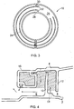
- the hydraulic seal arrangement comprises a hydraulic seal which may be used, for example, to seal between concentrically arranged inner and outer shafts 2, 4 of a multi-spool engine.
- the inner and outer shafts 2, 4 rotate at different speeds about a common axis and the hydraulic seal is used to seal a relatively high pressure region 6 from a relatively low pressure region 8.
- the inner shaft 2 comprises an annular seal member or fin 10 which projects radially outward from the inner shaft 2 and extends around the entire circumference of the inner shaft 2.
- the outer shaft 4 comprises an annular trough 12 which faces radially inward and extends around the entire circumference of the outer shaft 4.
- the fin 10 of the inner shaft 2 is received within the trough 12 of the outer shaft 4.
- the inner shaft 2 further comprises an inlet port 14.
- the inlet port 14 supplies hydraulic fluid (e.g. oil) in a radial direction to the side of trough 12 adjacent the low pressure region 8.
- the outer shaft 4 further comprises an annular reservoir 16.
- the annular reservoir 16 is arranged to retain fluid from the hydraulic seal when the engine is shutdown and to return the retained fluid to the hydraulic seal under centrifugal force after the engine is restarted.
- the annular reservoir 16 is divided into an inner chamber 18, a central chamber 20 and an outer chamber 22.
- the inner chamber 18 is separated from the central chamber 20 by a circumferential partition wall 24.
- the outer chamber 22 is separated from the central chamber 20 by a circumferential partition wall 24.
- the partition walls 24 extend around the majority of the circumference of the annular reservoir 16. However, the partition walls 24 are not continuous and terminate to form a transition region 26. In the transition region 26, the annular reservoir 16 is undivided and thus fluid may traverse between the inner, central and outer chambers 18, 20, 22. The transition region 26 therefore provides fluid communication between the chambers.
- the inner chamber 18 is provided with an opening 28 which is oriented in a substantially radial direction.
- the outer chamber 22 is provided with an opening 30 which is oriented in a substantially axial direction.
- the openings 28, 30 are disposed at substantially the same circumferential position about the annular reservoir 16.
- the openings 28, 30 of the inner and outer chambers 18, 22 are each separated from the transition region 26 by a substantially radial dividing wall 32.
- hydraulic fluid e.g. oil
- the rotation of the outer shaft 4 creates sufficient centrifugal force to retain the hydraulic fluid within the trough 12. Accordingly, an annulus of hydraulic fluid is formed in the trough 12.
- the fin 10 is partially submerged in the annulus of hydraulic fluid held by the trough 12. Consequently, a seal is formed and the difference in air pressure between the high pressure region 6 and the low pressure region 8 is compensated for by a difference in the fluid level on either side of the fin 10 (akin to a U-tube manometer).
- the supply of hydraulic fluid from the inlet port 14 causes the fluid to flow through the trough 12. A portion of the hydraulic fluid flows into the annular reservoir 16 via the opening 30 of the outer chamber 22. The hydraulic fluid flows through the annular reservoir 16 before exiting through the opening 28 of the inner chamber 18.
- the hydraulic fluid which has passed through the hydraulic seal either directly or via the annular reservoir 16 is recovered by a scavenge pump and is reused. This continuous flow of hydraulic fluid prevents overheating and coking.
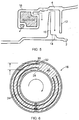
- the outer shaft 4 In order for a seal to form, the outer shaft 4 must rotate at sufficient speed to create the annulus of hydraulic fluid. When the speed of rotation is reduced such that there is insufficient centrifugal force, the hydraulic fluid will fall towards the centre of the engine, as shown in Figure 5 . The collapse of the annulus of hydraulic fluid results in the loss of sealing between the high pressure region 6 and the low pressure region 8.
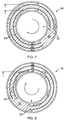
- hydraulic fluid is allowed to drain out of the inner and outer chambers 18, 22 under gravity, as depicted in Figures 6 and 7 .
- a portion of the hydraulic fluid contained in the central chamber 20 is also allowed to drain out of the annular reservoir 16 via the transition region 26 and the inner chamber 18.
- the quantity of retained hydraulic fluid is determined by the geometry of the annular reservoir 16 and its chambers and thus is independent of the hydraulic seal itself.
- the final retained volume of hydraulic fluid is therefore not dependent on the time taken nor the rate with which the annular reservoir 16 comes to a stationary position. Furthermore, it is also independent of the final angular orientation of the annular reservoir 16.
- the centrifugal force generated will force the hydraulic fluid to the outside of the transition region 26 and into the outer chamber 22 where it can exit the annular reservoir 16 through the opening 30.
- the hydraulic fluid is redistributed within the trough 12 to form the seal. Any subsequent pressure difference across the seal will displace the hydraulic fluid to provide a sealing capability.
- the seal is thus able to form without receiving any additional hydraulic fluid from the inlet port 14.
- conventional intershaft hydraulic seal designs require a dedicated hydraulic fluid feed in order to reach maximum sealing capability. This may compromise sealing capability at low speed until sufficient fluid is provided to the hydraulic seal.
- the present invention therefore mitigates risk associated with insufficient retained fluid volume and/or delayed fluid feed which may be evident in a conventional intershaft hydraulic seal design.
- the annular reservoir and hydraulic seal arrangement is well suited to the space envelope associated with hydraulic seal applications.
- the inlet port 14 may subsequently provide additional hydraulic fluid to the hydraulic seal in order to refill the annular reservoir 16 and to return to normal operation as depicted in Figure 4 .
- the retained hydraulic fluid is sufficient to completely fill the hydraulic seal.
- the geometry of the annular reservoir 16 can be defined to retain anything from 0-100% of the oil required to fill the hydraulic seal.
- the annular reservoir may comprise a valve or piston ring arrangement which allows fluid to flow into and/or out of the reservoir under certain conditions.
- the annular reservoir may comprise a valve which selectively closes an opening in the annular reservoir in response to the rotational speed of the machine. For example, when the speed of the machine is above a predetermined threshold (as experienced under normal operating conditions) the valve may be maintained in an open position to allow fluid to flow into and/or through the annular reservoir. The valve may then close when the speed of rotation falls below the predetermined threshold in order to retain the fluid within the reservoir. When the speed of rotation exceeds the predetermined threshold the valve returns to the open position to allow the fluid to return to the hydraulic seal.
- a predetermined threshold as experienced under normal operating conditions
- valve arrangement would simplify the geometric shape of the annular reservoir. Furthermore, this arrangement may be particularly useful in a bi-directional machine where it may rotate clockwise or anticlockwise.
- the reservoir has been described as being annular, this does not necessarily imply that the reservoir is circular.
- the reservoir may form any continuous shape, such as an oval, rectangle, etc.
- the annular reservoir 16 has been described as being located on the high pressure side of the hydraulic seal, this need not be the case.
- the annular reservoir may be located on either or both the high and low pressure sides of the hydraulic seal. That said it may be advantageous to position the annular reservoir on the opposite side of the hydraulic seal to the inlet port which supplies hydraulic fluid to the hydraulic seal.
- the annular reservoir may be located on the inner shaft instead of the outer shaft.
- the annular reservoir may be positioned on the annular fin.
- annular reservoir is shown with one hydraulic seal, depending on the application one or more annular reservoirs could provide hydraulic fluid to one or more hydraulic seals.
- the dividing walls 32 need not be oriented in a radial direction as shown and described herein. For example, it may be advantageous to angle the dividing walls 32 to provide a funnel to channel the fluid from the transition region 26 into the central chamber 20.
- the number of chambers within the annular reservoir may vary and be dependent on the requirements of the application. Furthermore, the number of openings to the annular reservoir may be altered and is dependent on the application. In addition, the inner and outer chambers are shown as being internal to the reservoir; however they may be internal or external to the main reservoir.
- annular reservoir has been described with reference to an intershaft hydraulic seal, it could be used in any application where a component or system may suffer from fluid starvation or a delay in fluid feed and thus it is desired to provide an immediate hydraulic fluid feed.
- the annular reservoir may be used with: hydraulic traps, splines, bearings, gears, pumps, jets, etc.
Landscapes
- Engineering & Computer Science (AREA)
- General Engineering & Computer Science (AREA)
- Mechanical Engineering (AREA)
- Sealing Devices (AREA)
- Sealing Using Fluids, Sealing Without Contact, And Removal Of Oil (AREA)
Claims (14)
- Système d'étanchéité hydraulique pour machine rotative, le système d'étanchéité hydraulique comprenant:un joint d'étanchéité hydraulique ; etun réservoir annulaire (16) accouplé de manière fluide au joint d'étanchéité hydraulique ;où le réservoir annulaire (16) est configuré pour retenir le liquide provenant du joint d'étanchéité hydraulique lorsque la machine est à l'arrêt et pour retourner le liquide retenu vers le joint d'étanchéité hydraulique en appliquant une force centrifuge après le redémarrage de la machine,où le réservoir (16) comprend une chambre intérieure (18) ayant une ouverture (28), une chambre extérieure (22) ayant une ouverture (30) et une chambre centrale (20) en communication fluide avec la chambre intérieure (18) et la chambre extérieure (22).
- Système d'étanchéité hydraulique selon la revendication 1, où le réservoir annulaire (16) comprend une ou plusieurs ouvertures (28, 30) permettent au fluide de pénétrer dans le réservoir pendant le fonctionnement normal et/ou de sortir du réservoir (16) après le redémarrage de la machine.
- Système d'étanchéité hydraulique selon la revendication 2, où le réservoir annulaire (16) comprend une vanne qui referme l'ouverture de manière sélective.
- Système d'étanchéité hydraulique selon la revendication 3, où la vanne referme de façon sélective l'ouverture (28, 30) en réponse à la vitesse de rotation de la machine.
- Système d'étanchéité hydraulique selon l'une quelconque des revendications précédentes, où le réservoir est configuré de telle sorte que dans des conditions normales de fonctionnement, le fluide pénètre dans le réservoir (16) par l'ouverture (30) de la chambre extérieure (22) et sort du réservoir (16) par l'ouverture (28) de la chambre intérieure (18).
- Système d'étanchéité hydraulique selon l'une quelconque des revendications précédentes, où le réservoir (16) est configuré de telle sorte qu'à la mise hors tension de la machine, la chambre intérieure (18) et la chambre extérieure (22) du réservoir (16) sont drainées de fluide et la chambre centrale (20) conserve le fluide.
- Système d'étanchéité hydraulique selon la revendication 6, où le fluide retenu est renvoyé au joint hydraulique après le redémarrage de la machine par l'ouverture (30) de la chambre extérieure (22).
- Système d'étanchéité hydraulique selon l'une quelconque des revendications précédentes, où la chambre extérieure (22) est éloignée radialement vers l'extérieur par rapport à au moins une partie de la chambre centrale (22) et où la chambre intérieure (18) est éloignées radialement vers l'intérieur par rapport à au moins une partie de la chambre centrale (20).
- Système d'étanchéité hydraulique selon l'une quelconque des revendications précédentes, où la chambre intérieure (18), la chambre extérieur (22) et la chambre centrale (20) sont séparées par des cloisons (24).
- Système d'étanchéité hydraulique selon la revendication 9, où les cloisons (24) s'étendent autour de seulement une partie de la circonférence du réservoir annulaire (16) et se terminent dans une région de transition (26) où un fluide peut passer entre les chambres.
- Système d'étanchéité hydraulique selon la revendication 10, où l'une des extrémités de la chambre intérieure (18) et de la chambre extérieure (22) est séparée de manière étanche de la zone de transition (26) par un mur de séparation (32).
- Système d'étanchéité hydraulique selon l'une quelconque des revendications précédentes, où la chambre intérieure (18) et la chambre extérieure (22) sont espacées l'une de l'autre dans une direction axiale.
- Système d'étanchéité hydraulique selon l'une quelconque des revendications précédentes, où l'ouverture (30) de la chambre extérieure (22) est orientée dans une direction substantiellement axiale et/ou l'ouverture (28) de la chambre intérieure (18) est orientée dans une direction substantiellement radiale.
- Moteur à turbine à gaz comprenant un système d'étanchéité hydraulique selon l'une quelconque des revendications précédentes.
Applications Claiming Priority (1)
| Application Number | Priority Date | Filing Date | Title |
|---|---|---|---|
| GB201221957 | 2012-12-06 |
Publications (2)
| Publication Number | Publication Date |
|---|---|
| EP2740976A1 EP2740976A1 (fr) | 2014-06-11 |
| EP2740976B1 true EP2740976B1 (fr) | 2016-06-22 |
Family
ID=49554161
Family Applications (1)
| Application Number | Title | Priority Date | Filing Date |
|---|---|---|---|
| EP13192821.0A Active EP2740976B1 (fr) | 2012-12-06 | 2013-11-14 | Agencement de joint hydraulique |
Country Status (2)
| Country | Link |
|---|---|
| US (1) | US9157532B2 (fr) |
| EP (1) | EP2740976B1 (fr) |
Families Citing this family (5)
| Publication number | Priority date | Publication date | Assignee | Title |
|---|---|---|---|---|
| GB201511456D0 (en) * | 2015-06-30 | 2015-08-12 | Rolls Royce Plc | A seal |
| KR102607230B1 (ko) | 2015-12-03 | 2023-11-27 | 호르톤 인코포레이티드 | 점성 클러치 유체 포착 시스템 |
| US10371263B2 (en) * | 2017-06-23 | 2019-08-06 | United Technologies Corporation | Hydraulic seal for non-mainshaft, rotating to static |
| FR3068079B1 (fr) * | 2017-06-27 | 2019-08-23 | Safran Helicopter Engines | Dispositif de joint hydraulique a amorcage ameliore |
| FR3123702B1 (fr) | 2021-06-04 | 2023-04-28 | Safran Helicopter Engines | Systeme d’etancheite hydraulique a alimentation par levre |
Family Cites Families (23)
| Publication number | Priority date | Publication date | Assignee | Title |
|---|---|---|---|---|
| DE195490C (fr) * | ||||
| US822802A (en) * | 1905-11-24 | 1906-06-05 | Wilkinson Turbine Company | Shaft-packing. |
| US876613A (en) * | 1906-05-07 | 1908-01-14 | Wilkinson Turbine Company | Shaft-packing. |
| US1749586A (en) * | 1924-03-28 | 1930-03-04 | Westinghouse Electric & Mfg Co | Oil-sealing ring for turbine bearings |
| US2133879A (en) * | 1936-04-28 | 1938-10-18 | Gen Electric | Shaft packing |
| US2573425A (en) * | 1947-06-23 | 1951-10-30 | Ethel K Haferkamp | Seal for centrifugal machines |
| US2823052A (en) * | 1954-04-12 | 1958-02-11 | Gen Motors Corp | Fluid seal device |
| GB1212593A (en) * | 1968-01-25 | 1970-11-18 | British Aircraft Corp Ltd | Improvements relating to rotary large diameter gas seals |
| US4335885A (en) * | 1980-08-19 | 1982-06-22 | Mechanical Technology Incorporated | Plural fluid magnetic/centrifugal seal |
| CA1173872A (fr) | 1981-08-20 | 1984-09-04 | Hooshang Heshmat | Garniture d'etancheite lalyrinthine a diffusion centrifuge de fluide ferromagnetique |
| US4527802A (en) * | 1983-03-21 | 1985-07-09 | Mechanical Technology Incorporated | Integral magnetic fluid centrifugal high speed gas seal and method |
| GB8318582D0 (en) * | 1983-07-08 | 1983-08-10 | Rolls Royce | Air separation and lubricant scavenge apparatus |
| US4671677A (en) * | 1985-05-20 | 1987-06-09 | Mechanical Technology Incorporated | Fluid seal with shaft excursion compensation |
| JPS62261765A (ja) * | 1986-05-06 | 1987-11-13 | Matsushita Seiko Co Ltd | 空気調和機のフアン軸シ−ル装置 |
| EP0561014A1 (fr) * | 1992-03-16 | 1993-09-22 | BECKER VERFAHRENSTECHNIK, DIPL. ING. ERNST BECKER GmbH & CO KG | Joint dynamique d'étanchéité sans contact |
| GB9801561D0 (en) * | 1998-01-27 | 1998-03-25 | Rolls Royce Plc | Hydraulic seal |
| DE19916803A1 (de) * | 1999-04-14 | 2000-10-19 | Rolls Royce Deutschland | Hydraulische Dichtungsanordnung insbesondere an einer Gasturbine |
| JP2003148632A (ja) | 2001-11-12 | 2003-05-21 | Ishikawajima Harima Heavy Ind Co Ltd | 回転機械の回転軸シール機構 |
| DE10201055A1 (de) * | 2002-01-14 | 2003-07-24 | Rolls Royce Deutschland | Hydraulische Dichtungsanordnung |
| US6845987B2 (en) * | 2002-09-10 | 2005-01-25 | United Technologies Corporation | Shaft seal |
| DE102005047696A1 (de) | 2005-09-27 | 2007-03-29 | Rolls-Royce Deutschland Ltd & Co Kg | Siphonartige hydraulische Dichtung zwischen zwei konzentrisch angeordneten Wellen |
| DE102007060890A1 (de) * | 2007-12-14 | 2009-06-18 | Rolls-Royce Deutschland Ltd & Co Kg | Abdichtung mindestens einer Welle mit mindestens einer hydraulischen Dichtung |
| GB0818726D0 (en) * | 2008-10-14 | 2008-11-19 | Rolls Royce Plc | A seal |
-
2013
- 2013-11-14 EP EP13192821.0A patent/EP2740976B1/fr active Active
- 2013-11-14 US US14/080,438 patent/US9157532B2/en active Active
Also Published As
| Publication number | Publication date |
|---|---|
| EP2740976A1 (fr) | 2014-06-11 |
| US20140158232A1 (en) | 2014-06-12 |
| US9157532B2 (en) | 2015-10-13 |
Similar Documents
| Publication | Publication Date | Title |
|---|---|---|
| US9157532B2 (en) | Hydraulic seal arrangement | |
| SE456028B (sv) | Ringformig vetskepump med konisk eller cylindrisk portdel | |
| EP2726704A2 (fr) | Pompe pour puits avec section de joint comprenant un passage d'écoulement à labyrinthe dans un soufflet métallique | |
| RU2662845C2 (ru) | Проточный насос с трубками пито с зубчатым приводом | |
| CN110462182B (zh) | 用于涡轮机的离心脱气器 | |
| JP5589532B2 (ja) | ベーンポンプ | |
| US6921079B2 (en) | Hydraulic seal arrangement | |
| CN103711879A (zh) | 一种风电齿轮箱机械迷宫密封结构 | |
| EP3027908B1 (fr) | Pompe de graissage à palettes à débit variable | |
| JP6470950B2 (ja) | ペンジュラムスライダポンプ | |
| EP3112729B1 (fr) | Joint | |
| EP2177795B1 (fr) | Joint | |
| JP2017125457A (ja) | オイルフリースクリュ圧縮機 | |
| WO2016067490A1 (fr) | Dispositif d'arbre principal | |
| CN110388243B (zh) | 凸轮轴相位器 | |
| RU2534339C1 (ru) | Турбина двухроторного газотурбинного двигателя | |
| CN106763781B (zh) | 转动机械的液体密封结构 | |
| JP2016118112A (ja) | ポンプ装置 | |
| JP6210957B2 (ja) | 潤滑油排出機構 | |
| JP2019173956A5 (ja) | 遠心圧縮機及びメカニカルシール | |
| AU2016219196B2 (en) | A liquid ring pump port member having anti-cavitation constructions | |
| JP2025075664A (ja) | シール構造 | |
| SE1551629A1 (sv) | Lagringsarrangemang för en under högt tryck arbetande inbördes vridbar enhet | |
| RU2548331C1 (ru) | Турбонасосный агрегат | |
| WO2025070519A1 (fr) | Composant coulissant |
Legal Events
| Date | Code | Title | Description |
|---|---|---|---|
| PUAI | Public reference made under article 153(3) epc to a published international application that has entered the european phase |
Free format text: ORIGINAL CODE: 0009012 |
|
| 17P | Request for examination filed |
Effective date: 20131114 |
|
| AK | Designated contracting states |
Kind code of ref document: A1 Designated state(s): AL AT BE BG CH CY CZ DE DK EE ES FI FR GB GR HR HU IE IS IT LI LT LU LV MC MK MT NL NO PL PT RO RS SE SI SK SM TR |
|
| AX | Request for extension of the european patent |
Extension state: BA ME |
|
| R17P | Request for examination filed (corrected) |
Effective date: 20141210 |
|
| RBV | Designated contracting states (corrected) |
Designated state(s): AL AT BE BG CH CY CZ DE DK EE ES FI FR GB GR HR HU IE IS IT LI LT LU LV MC MK MT NL NO PL PT RO RS SE SI SK SM TR |
|
| RAP1 | Party data changed (applicant data changed or rights of an application transferred) |
Owner name: ROLLS-ROYCE PLC |
|
| GRAP | Despatch of communication of intention to grant a patent |
Free format text: ORIGINAL CODE: EPIDOSNIGR1 |
|
| GRAS | Grant fee paid |
Free format text: ORIGINAL CODE: EPIDOSNIGR3 |
|
| GRAA | (expected) grant |
Free format text: ORIGINAL CODE: 0009210 |
|
| INTG | Intention to grant announced |
Effective date: 20160428 |
|
| AK | Designated contracting states |
Kind code of ref document: B1 Designated state(s): AL AT BE BG CH CY CZ DE DK EE ES FI FR GB GR HR HU IE IS IT LI LT LU LV MC MK MT NL NO PL PT RO RS SE SI SK SM TR |
|
| REG | Reference to a national code |
Ref country code: GB Ref legal event code: FG4D |
|
| REG | Reference to a national code |
Ref country code: CH Ref legal event code: EP |
|
| REG | Reference to a national code |
Ref country code: IE Ref legal event code: FG4D |
|
| REG | Reference to a national code |
Ref country code: AT Ref legal event code: REF Ref document number: 807859 Country of ref document: AT Kind code of ref document: T Effective date: 20160715 |
|
| REG | Reference to a national code |
Ref country code: DE Ref legal event code: R096 Ref document number: 602013008725 Country of ref document: DE |
|
| REG | Reference to a national code |
Ref country code: LT Ref legal event code: MG4D |
|
| REG | Reference to a national code |
Ref country code: NL Ref legal event code: MP Effective date: 20160622 |
|
| PG25 | Lapsed in a contracting state [announced via postgrant information from national office to epo] |
Ref country code: LT Free format text: LAPSE BECAUSE OF FAILURE TO SUBMIT A TRANSLATION OF THE DESCRIPTION OR TO PAY THE FEE WITHIN THE PRESCRIBED TIME-LIMIT Effective date: 20160622 Ref country code: FI Free format text: LAPSE BECAUSE OF FAILURE TO SUBMIT A TRANSLATION OF THE DESCRIPTION OR TO PAY THE FEE WITHIN THE PRESCRIBED TIME-LIMIT Effective date: 20160622 Ref country code: NO Free format text: LAPSE BECAUSE OF FAILURE TO SUBMIT A TRANSLATION OF THE DESCRIPTION OR TO PAY THE FEE WITHIN THE PRESCRIBED TIME-LIMIT Effective date: 20160922 |
|
| REG | Reference to a national code |
Ref country code: AT Ref legal event code: MK05 Ref document number: 807859 Country of ref document: AT Kind code of ref document: T Effective date: 20160622 |
|
| REG | Reference to a national code |
Ref country code: FR Ref legal event code: PLFP Year of fee payment: 4 |
|
| PG25 | Lapsed in a contracting state [announced via postgrant information from national office to epo] |
Ref country code: HR Free format text: LAPSE BECAUSE OF FAILURE TO SUBMIT A TRANSLATION OF THE DESCRIPTION OR TO PAY THE FEE WITHIN THE PRESCRIBED TIME-LIMIT Effective date: 20160622 Ref country code: LV Free format text: LAPSE BECAUSE OF FAILURE TO SUBMIT A TRANSLATION OF THE DESCRIPTION OR TO PAY THE FEE WITHIN THE PRESCRIBED TIME-LIMIT Effective date: 20160622 Ref country code: SE Free format text: LAPSE BECAUSE OF FAILURE TO SUBMIT A TRANSLATION OF THE DESCRIPTION OR TO PAY THE FEE WITHIN THE PRESCRIBED TIME-LIMIT Effective date: 20160622 Ref country code: RS Free format text: LAPSE BECAUSE OF FAILURE TO SUBMIT A TRANSLATION OF THE DESCRIPTION OR TO PAY THE FEE WITHIN THE PRESCRIBED TIME-LIMIT Effective date: 20160622 Ref country code: GR Free format text: LAPSE BECAUSE OF FAILURE TO SUBMIT A TRANSLATION OF THE DESCRIPTION OR TO PAY THE FEE WITHIN THE PRESCRIBED TIME-LIMIT Effective date: 20160923 Ref country code: NL Free format text: LAPSE BECAUSE OF FAILURE TO SUBMIT A TRANSLATION OF THE DESCRIPTION OR TO PAY THE FEE WITHIN THE PRESCRIBED TIME-LIMIT Effective date: 20160622 |
|
| PG25 | Lapsed in a contracting state [announced via postgrant information from national office to epo] |
Ref country code: SK Free format text: LAPSE BECAUSE OF FAILURE TO SUBMIT A TRANSLATION OF THE DESCRIPTION OR TO PAY THE FEE WITHIN THE PRESCRIBED TIME-LIMIT Effective date: 20160622 Ref country code: IS Free format text: LAPSE BECAUSE OF FAILURE TO SUBMIT A TRANSLATION OF THE DESCRIPTION OR TO PAY THE FEE WITHIN THE PRESCRIBED TIME-LIMIT Effective date: 20161022 Ref country code: RO Free format text: LAPSE BECAUSE OF FAILURE TO SUBMIT A TRANSLATION OF THE DESCRIPTION OR TO PAY THE FEE WITHIN THE PRESCRIBED TIME-LIMIT Effective date: 20160622 Ref country code: IT Free format text: LAPSE BECAUSE OF FAILURE TO SUBMIT A TRANSLATION OF THE DESCRIPTION OR TO PAY THE FEE WITHIN THE PRESCRIBED TIME-LIMIT Effective date: 20160622 Ref country code: EE Free format text: LAPSE BECAUSE OF FAILURE TO SUBMIT A TRANSLATION OF THE DESCRIPTION OR TO PAY THE FEE WITHIN THE PRESCRIBED TIME-LIMIT Effective date: 20160622 Ref country code: CZ Free format text: LAPSE BECAUSE OF FAILURE TO SUBMIT A TRANSLATION OF THE DESCRIPTION OR TO PAY THE FEE WITHIN THE PRESCRIBED TIME-LIMIT Effective date: 20160622 |
|
| PG25 | Lapsed in a contracting state [announced via postgrant information from national office to epo] |
Ref country code: SM Free format text: LAPSE BECAUSE OF FAILURE TO SUBMIT A TRANSLATION OF THE DESCRIPTION OR TO PAY THE FEE WITHIN THE PRESCRIBED TIME-LIMIT Effective date: 20160622 Ref country code: PL Free format text: LAPSE BECAUSE OF FAILURE TO SUBMIT A TRANSLATION OF THE DESCRIPTION OR TO PAY THE FEE WITHIN THE PRESCRIBED TIME-LIMIT Effective date: 20160622 Ref country code: BE Free format text: LAPSE BECAUSE OF FAILURE TO SUBMIT A TRANSLATION OF THE DESCRIPTION OR TO PAY THE FEE WITHIN THE PRESCRIBED TIME-LIMIT Effective date: 20160622 Ref country code: AT Free format text: LAPSE BECAUSE OF FAILURE TO SUBMIT A TRANSLATION OF THE DESCRIPTION OR TO PAY THE FEE WITHIN THE PRESCRIBED TIME-LIMIT Effective date: 20160622 Ref country code: PT Free format text: LAPSE BECAUSE OF FAILURE TO SUBMIT A TRANSLATION OF THE DESCRIPTION OR TO PAY THE FEE WITHIN THE PRESCRIBED TIME-LIMIT Effective date: 20161024 Ref country code: ES Free format text: LAPSE BECAUSE OF FAILURE TO SUBMIT A TRANSLATION OF THE DESCRIPTION OR TO PAY THE FEE WITHIN THE PRESCRIBED TIME-LIMIT Effective date: 20160622 |
|
| REG | Reference to a national code |
Ref country code: DE Ref legal event code: R097 Ref document number: 602013008725 Country of ref document: DE |
|
| PLBE | No opposition filed within time limit |
Free format text: ORIGINAL CODE: 0009261 |
|
| STAA | Information on the status of an ep patent application or granted ep patent |
Free format text: STATUS: NO OPPOSITION FILED WITHIN TIME LIMIT |
|
| 26N | No opposition filed |
Effective date: 20170323 |
|
| PG25 | Lapsed in a contracting state [announced via postgrant information from national office to epo] |
Ref country code: DK Free format text: LAPSE BECAUSE OF FAILURE TO SUBMIT A TRANSLATION OF THE DESCRIPTION OR TO PAY THE FEE WITHIN THE PRESCRIBED TIME-LIMIT Effective date: 20160622 |
|
| REG | Reference to a national code |
Ref country code: CH Ref legal event code: PL |
|
| PG25 | Lapsed in a contracting state [announced via postgrant information from national office to epo] |
Ref country code: LI Free format text: LAPSE BECAUSE OF NON-PAYMENT OF DUE FEES Effective date: 20161130 Ref country code: CH Free format text: LAPSE BECAUSE OF NON-PAYMENT OF DUE FEES Effective date: 20161130 |
|
| REG | Reference to a national code |
Ref country code: IE Ref legal event code: MM4A |
|
| PG25 | Lapsed in a contracting state [announced via postgrant information from national office to epo] |
Ref country code: SI Free format text: LAPSE BECAUSE OF FAILURE TO SUBMIT A TRANSLATION OF THE DESCRIPTION OR TO PAY THE FEE WITHIN THE PRESCRIBED TIME-LIMIT Effective date: 20160622 |
|
| PG25 | Lapsed in a contracting state [announced via postgrant information from national office to epo] |
Ref country code: LU Free format text: LAPSE BECAUSE OF NON-PAYMENT OF DUE FEES Effective date: 20161130 |
|
| REG | Reference to a national code |
Ref country code: FR Ref legal event code: PLFP Year of fee payment: 5 |
|
| PG25 | Lapsed in a contracting state [announced via postgrant information from national office to epo] |
Ref country code: IE Free format text: LAPSE BECAUSE OF NON-PAYMENT OF DUE FEES Effective date: 20161114 |
|
| PG25 | Lapsed in a contracting state [announced via postgrant information from national office to epo] |
Ref country code: HU Free format text: LAPSE BECAUSE OF FAILURE TO SUBMIT A TRANSLATION OF THE DESCRIPTION OR TO PAY THE FEE WITHIN THE PRESCRIBED TIME-LIMIT; INVALID AB INITIO Effective date: 20131114 |
|
| PG25 | Lapsed in a contracting state [announced via postgrant information from national office to epo] |
Ref country code: MC Free format text: LAPSE BECAUSE OF FAILURE TO SUBMIT A TRANSLATION OF THE DESCRIPTION OR TO PAY THE FEE WITHIN THE PRESCRIBED TIME-LIMIT Effective date: 20160622 Ref country code: MK Free format text: LAPSE BECAUSE OF FAILURE TO SUBMIT A TRANSLATION OF THE DESCRIPTION OR TO PAY THE FEE WITHIN THE PRESCRIBED TIME-LIMIT Effective date: 20160622 Ref country code: CY Free format text: LAPSE BECAUSE OF FAILURE TO SUBMIT A TRANSLATION OF THE DESCRIPTION OR TO PAY THE FEE WITHIN THE PRESCRIBED TIME-LIMIT Effective date: 20160622 |
|
| PG25 | Lapsed in a contracting state [announced via postgrant information from national office to epo] |
Ref country code: BG Free format text: LAPSE BECAUSE OF FAILURE TO SUBMIT A TRANSLATION OF THE DESCRIPTION OR TO PAY THE FEE WITHIN THE PRESCRIBED TIME-LIMIT Effective date: 20160622 |
|
| PG25 | Lapsed in a contracting state [announced via postgrant information from national office to epo] |
Ref country code: MT Free format text: LAPSE BECAUSE OF NON-PAYMENT OF DUE FEES Effective date: 20161114 |
|
| PG25 | Lapsed in a contracting state [announced via postgrant information from national office to epo] |
Ref country code: AL Free format text: LAPSE BECAUSE OF FAILURE TO SUBMIT A TRANSLATION OF THE DESCRIPTION OR TO PAY THE FEE WITHIN THE PRESCRIBED TIME-LIMIT Effective date: 20160622 Ref country code: TR Free format text: LAPSE BECAUSE OF FAILURE TO SUBMIT A TRANSLATION OF THE DESCRIPTION OR TO PAY THE FEE WITHIN THE PRESCRIBED TIME-LIMIT Effective date: 20160622 |
|
| P01 | Opt-out of the competence of the unified patent court (upc) registered |
Effective date: 20230528 |
|
| PGFP | Annual fee paid to national office [announced via postgrant information from national office to epo] |
Ref country code: DE Payment date: 20251126 Year of fee payment: 13 |
|
| PGFP | Annual fee paid to national office [announced via postgrant information from national office to epo] |
Ref country code: GB Payment date: 20251125 Year of fee payment: 13 |
|
| PGFP | Annual fee paid to national office [announced via postgrant information from national office to epo] |
Ref country code: FR Payment date: 20251124 Year of fee payment: 13 |