EP2741406B1 - Moteur pas à pas à double rotor - Google Patents
Moteur pas à pas à double rotor Download PDFInfo
- Publication number
- EP2741406B1 EP2741406B1 EP13195544.5A EP13195544A EP2741406B1 EP 2741406 B1 EP2741406 B1 EP 2741406B1 EP 13195544 A EP13195544 A EP 13195544A EP 2741406 B1 EP2741406 B1 EP 2741406B1
- Authority
- EP
- European Patent Office
- Prior art keywords
- rotor
- teeth
- stator
- pitch
- axis
- Prior art date
- Legal status (The legal status is an assumption and is not a legal conclusion. Google has not performed a legal analysis and makes no representation as to the accuracy of the status listed.)
- Active
Links
- 238000006073 displacement reaction Methods 0.000 description 11
- 239000003638 chemical reducing agent Substances 0.000 description 2
- 238000010586 diagram Methods 0.000 description 2
- 230000007246 mechanism Effects 0.000 description 2
- 125000006850 spacer group Chemical group 0.000 description 2
- 230000007704 transition Effects 0.000 description 2
- 230000005672 electromagnetic field Effects 0.000 description 1
- 239000000463 material Substances 0.000 description 1
- 230000003287 optical effect Effects 0.000 description 1
Images




Classifications
-
- H—ELECTRICITY
- H02—GENERATION; CONVERSION OR DISTRIBUTION OF ELECTRIC POWER
- H02K—DYNAMO-ELECTRIC MACHINES
- H02K37/00—Motors with rotor rotating step by step and without interrupter or commutator driven by the rotor, e.g. stepping motors
- H02K37/10—Motors with rotor rotating step by step and without interrupter or commutator driven by the rotor, e.g. stepping motors of permanent magnet type
- H02K37/12—Motors with rotor rotating step by step and without interrupter or commutator driven by the rotor, e.g. stepping motors of permanent magnet type with stationary armatures and rotating magnets
- H02K37/14—Motors with rotor rotating step by step and without interrupter or commutator driven by the rotor, e.g. stepping motors of permanent magnet type with stationary armatures and rotating magnets with magnets rotating within the armatures
-
- H—ELECTRICITY
- H02—GENERATION; CONVERSION OR DISTRIBUTION OF ELECTRIC POWER
- H02K—DYNAMO-ELECTRIC MACHINES
- H02K16/00—Machines with more than one rotor or stator
- H02K16/02—Machines with one stator and two or more rotors
- H02K16/025—Machines with one stator and two or more rotors with rotors and moving stators connected in a cascade
-
- H—ELECTRICITY
- H02—GENERATION; CONVERSION OR DISTRIBUTION OF ELECTRIC POWER
- H02K—DYNAMO-ELECTRIC MACHINES
- H02K37/00—Motors with rotor rotating step by step and without interrupter or commutator driven by the rotor, e.g. stepping motors
- H02K37/02—Motors with rotor rotating step by step and without interrupter or commutator driven by the rotor, e.g. stepping motors of variable reluctance type
- H02K37/04—Motors with rotor rotating step by step and without interrupter or commutator driven by the rotor, e.g. stepping motors of variable reluctance type with rotors situated within the stators
Definitions
- the invention lies in the field of precision mechanical actuators. It relates to a high-precision stepping motor and can in particular be used in the actuation mechanisms of artificial satellites.
- Artificial satellites generally require numerous actuation devices. These devices can in particular be used to deploy panels from a storage configuration to a deployed configuration, to orient pointing mechanisms in different directions, or to actuate elements of optical instruments such as mirrors.
- the spatial context imposes constraints in terms of power consumption, reliability, weight and size.
- the actuating devices must often have a high precision, that is to say a low angular resolution in the case of rotary motors.
- Stepper motors are commonly used as mechanical actuators for aerospace applications. Indeed, this type of motor has several advantages, such as low friction, a possibility of holding in position without electrical consumption, and simplicity of control. In particular, no servo is necessary to maintain a particular position.
- Stepper motors also have low angular resolution, which can reach a few tenths of a degree. However, a decrease in angular resolution is accompanied by an increase in the size and mass of the motor. In addition, finer angular resolutions may be required.
- One solution is to add a mechanical reducer at the output of the stepper motor. The introduction of a reducer nevertheless involves a reduction in energy efficiency due to the friction it implies, and an increase in weight and size.
- Another solution is to control the stepper motor in microsteps. This solution requires more expensive electronics, and does not make it possible to maintain a holding torque without power.
- the patent US6700272 describes a reluctance motor comprising a stator, a rotor and an intermediate rotor in which the teeth of the stator do not have the same pitch as the teeth of the rotor facing it.
- the document US2010 / 0066184 describes a rotary electric machine comprising a stator and a rotor having pairs of magnetic poles having teeth distributed at a regular pitch but different from the pitch of the poles of the stator.
- the patent FR2724783 describes a stepping micro-motor comprising a stator and a rotor having the same number of pole teeth.
- the movements between the stator, the first rotor, and the second rotor are rotational movements along the axis.
- Each stator stud may include a first ring portion, an inner surface of which is toothed with the pitch p 1 , the teeth of the ring portion being able to align with teeth of the first set of the first rotor.
- Each stator stud may also comprise a second portion of ring whose inner surface is toothed with the pitch p 1 , the second portion of ring being arranged symmetrically along the axis with respect to the first portion of ring, the teeth of the second portion of ring being able to align with teeth of the first set of the first rotor.
- the first rotor and the second rotor can then each comprise N concentric rings distributed along the axis and electromagnetically isolated from each other, the first and second ring portions of each stator pad aligning with one of the rings of the first rotor and with one of the rings of the second rotor, so as to allow the circulation of a magnetic field between the first portion of ring and the second portion of ring.
- the first rotor comprises two integral parts in rotation along the axis, each part comprising N concentric rings distributed along the axis and electromagnetically isolated from each other, an outer surface of each ring comprising teeth distributed according to the step p 1 and aligned between the different rings, an inner surface of each ring comprising teeth distributed according to the step p 2 and aligned between the different rings, the second rotor comprising two parts integral in rotation about the axis, each part of the second rotor comprising N concentric rings distributed along the axis and electromagnetically isolated from each other, an outer surface of each ring comprising teeth distributed along the step p 2 and offset with respect to the teeth of the other rings of the step p ' 2 , each ring of the first rotor coming to align with one of the rings of the second rotor.
- each stator stud can comprise four concentric ring portions, each ring portion being toothed with the pitch p 1 , for each stator stud, a first ring portion and a second ring portion being arranged symmetrically along the axis and coming to cooperate with one of the rings of the first part of the first rotor and with one of the rings of the first part of the second rotor, a third ring portion and a fourth ring portion being arranged symmetrically along the axis and coming to cooperate with one of the rings of the second part of the first rotor and with one of the rings of the second part of the second rotor.
- the invention particularly has the advantage that it allows the stepping motor to be controlled in full step while having a very low angular movement between the second rotor and the stator between two successive supply phases.
- the figure 1 represents, in the form of a simplified block diagram, a first example of a stepping motor according to the invention.
- the motor is shown here as a linear motor. However, it could also be a rotary motor in a flat representation.
- the stepping motor 10 shown in the figure 1 comprises a stator 11, a first rotor 12, and a second rotor 13 comprising a permanent magnet 14.
- the stator 11 comprises four stator pads 111 to 114. Each stator pad 111-114 comprises two teeth 115 spaced from one another with a pitch p 1 , and a coil 116 which can be supplied with an electric current in order to create an electromagnetic field.
- the stator pads 111-114 are distributed on the stator 11 according to a step p 1 (2 + 1 / N).
- stator pads are arranged so that one of the teeth 115 of a stator pad 111-114 is located at a distance p ' 1 from an adjoining stator pad.
- the pitch p ' 1 is determined as a function of the pitch p 1 and the number N of stator pads. It is equal to (1 + 1 /N).p 1 , i.e. in the example of the figure 1 , (1 + 1/4) .p 1 .
- the first rotor 12, also called intermediate rotor is in sliding connection with respect to the stator 11 along an axis X (or in pivot connection along an axis orthogonal to the axis X in the case of a rotary motor).
- the slide connection must be understood in the broad sense, that is to say that the connection must include at least one degree of freedom in translation along the axis X.
- the intermediate rotor 12 comprises a first set of teeth 121 distributed along the not p 1 and coming opposite the teeth 115 of the stator pads 111-114. Due to the difference between the steps p 1 and p ' 1 , the teeth 115 of all the stator pads 111-114 cannot be aligned simultaneously with the teeth 121 of the intermediate rotor 12. At each step of the motor, two teeth 121 align with teeth 115 on one of the stator studs 111-114.
- the intermediate rotor 12 further comprises a second set of teeth 122 distributed in a pitch p 2 , different from the pitch p 1 .
- the second rotor 13 also called central rotor, is in sliding connection with respect to the intermediate rotor 12 along the axis X (or in pivot connection in the case of a rotary motor). It is therefore also in sliding connection with respect to the stator 11.
- the central rotor 13 comprises four sets 131 to 134 of teeth 135, called rotor pads, by analogy with the stator pads 111-114.
- the central rotor 13 comprises N rotor pads, ie as many rotor pads as stator pads.
- Each rotor stud 131-134 comprises two teeth 135 spaced from each other by the pitch p 2 .
- the rotor pads 131-134 are distributed in a step p 2 (2 + 1 / N).
- the rotor pads are arranged so that one of the teeth 135 of a rotor pad 131-134 is located at a distance p ′ 2 from an adjoining rotor pad.
- the pitch p ' 2 is determined as a function of the pitch p 2 and the number N of rotor and stator pads. It is equal to (1 + 1 / N) .p 2 , i.e. in the example of the figure 1 , (1 + 1/4) .p 2 . Due to the difference between the steps p 2 and p ' 2 , the teeth 135 of all the rotor pads 131-134 cannot be aligned simultaneously with the teeth 122 of the intermediate rotor 12.
- two teeth 122 are aligned with teeth 135 of one of the rotor studs 131-134.
- the permanent magnet 14 is attached to the central rotor 13 so as to create or increase the circulation of magnetic current between the stator pads 111-114 and the rotor pads 131-134.
- the figures 2 to 6 illustrate the operation of the stepping motor 10 shown diagrammatically on the figure 1 during its successive feeding phases.
- a phase corresponds to a period of time during which a coil 116 of one of the stator pads 111-114 is supplied.
- the coil itself can also be called "phase”.
- the intermediate rotor 12 and the central rotor 13 are positioned so as to minimize the reluctance between one of the stator pads 111-114 and the corresponding rotor pad 131-134.
- the figure 2 shows the respective positions of the stator 11, the intermediate rotor 12 and the central rotor 13 during a first phase, in this case when the coil 116 of the stator pad 111 is supplied.
- two teeth 121 of the intermediate rotor 12 are aligned with the teeth 115 of the stator stud 111, and two teeth 122 of the intermediate rotor 12 are aligned with the teeth 135 of the rotor pad 131.
- the magnetic field 20 established between the stator pad 111 and the rotor pad 131 is then maximum.
- the figure 3 represents the stepping motor 10 during the second phase, that is to say when the coil 116 of the second stator pad 112 is supplied.
- the positions of the intermediate rotor 12 and the central rotor 13 during the first phase are shown in broken lines.
- two teeth 121 of the intermediate rotor 12 are aligned with the teeth 115 of the stator block 112, and two teeth 122 of the intermediate rotor 12 are aligned with the teeth 135 of the rotor block 132.
- the passage from the first alignment between the teeth 115 of the stator block 111 and the teeth 121 of the intermediate rotor 12, to the second alignment between the teeth 115 of the stator block 112 and the teeth 121 of the rotor intermediate 12 causes the intermediate rotor 12 to move relative to stator 11 by a distance d 1 equal to p 1 / N, in this case p 1/4 .
- the passage from the first alignment between the teeth 122 of the intermediate rotor 12 and the teeth 135 of the rotor stud 131, to the second alignment between the teeth 122 of the intermediate rotor 12 and the teeth 135 of the rotor stud 132 causes the rotor to move.
- the intermediate rotor 12 is driven in a first direction S 1
- the central rotor 13 is driven in a second direction S 2 , opposite to the first.
- the distance d 3 traveled by the central rotor 13 relative to the stator 11 is equal to the distance (d 2 -d 1 ), that is to say (p 2 -p 1 ) / N. It follows that the distance d 3 can be chosen as small as desired by choosing appropriate values of steps p 1 and p 2 .
- the figure 4 represents the stepping motor 10 during the third phase, that is to say when the coil 116 of the third stator pad 113 is supplied.
- the intermediate rotor 12 and the central rotor 13 are also shown in broken lines in the positions they occupied during the first phase.
- this third phase it is the teeth 115 of the stator pad 113 which align with teeth 121 of the intermediate rotor 12, and the teeth 135 of the rotor pad 133 which align with teeth 122 of the intermediate rotor 12
- the transition from the alignments of the second phase to the alignments of the third phase causes a new displacement of the intermediate rotor 12 relative to the stator 11 of distance d 1 and direction S 1 , and a new displacement of the central rotor 13 relative to the rotor intermediate 12 with distance d 2 and direction S 2 .
- the central rotor 13 has therefore undergone a displacement equal to 2. (d 2 -d 1 ) since the first phase.
- the figure 5 represents the stepping motor 10 during the fourth phase, that is to say when the coil 116 of the fourth stator pad 114 is supplied.
- the teeth 115 of the stator stud 114 are aligned with teeth 121 of the intermediate rotor 12, and the teeth 135 of the rotor stud 134 come to align with teeth 122 of the intermediate rotor 12.
- the passage of the alignments of the third phase with the alignments of the third phase causes a new displacement of the intermediate rotor 12 relative to the stator 11 of distance d 1 and direction S 1 , and a new displacement of the central rotor 13 relative to the intermediate rotor 12 of distance d 2 and meaning S 2 .
- the central rotor 13 has therefore undergone a displacement equal to 3. (d 2 -d 1 ) from the first phase.
- the figure 6 represents the stepper motor 10 during the fifth phase.
- This phase corresponds in fact to the first phase, in which the coil of the first stator pad 111 is supplied.
- the same alignments as those of the first phase are obtained.
- the successive passages from the first to the fifth phase have thus resulted in a displacement of the intermediate rotor 12 relative to the stator 11 of distance p 1 - i.e. 4.d 1 - and of direction S 1 , and a displacement of the central rotor 13 with respect to to the rotor intermediate 12 of distance p 2 - i.e. 4.d 2 - and of direction S 2 . Consequently, the displacement of the central rotor 13 relative to the stator 11 is equal to p 2 -p 1 .
- the embodiment of the stepper motor of the figure 1 can be generalized.
- the invention can be applied to rotary stepper motors.
- the movements of the rotors are rotational movements, and the steps considered are angular steps.
- it has been considered a number N of rotor pads and stator pads equal to four.
- the number N can however take any integer value greater than or equal to three.
- each stator pad and each rotor pad may include one or more teeth. With a whole representing the number of teeth of each stator pad, the stator pads are distributed on the stator at a step equal to p 1 (a + 1 / N).
- the rotor pads are distributed over the rotor at a step equal to p 2 (b + 1 / N).
- the rotor and stator pads include the same number of teeth.
- a stud comprises a plurality of teeth
- these teeth are distributed according to the pitch p 1 or p 2 , depending on whether it is a stator or rotor stud, respectively.
- Each tooth positioned at the end of the plurality of teeth of a stator pad must be at the distance p ' 1 from one of the teeth of a consecutive stator pad.
- each tooth positioned at the end of the plurality of teeth of a rotor stud must be at the distance p ′ 2 from one of the teeth of a consecutive rotor stud.
- the steps p ' 1 and p' 2 have been indicated as being equal to (1 + 1 / N) .p 1 and (1 + 1 / N) .p 2 , respectively.
- these steps can also be equal to p 1 / N and p 2 / N, respectively.
- the stator, intermediate rotor and central rotor teeth have been shown diagrammatically in the Figures 1 to 6 in the form of triangles.
- any other form of teeth can be used in the context of the invention. More generally, the teeth can be replaced by any means capable of generating positions having a reluctance lower than that of the other positions. In particular, materials with different electromagnetic properties can be used.
- the step p 2 can be equal to 1.1 times the step p 1 . The difference between steps p 1 and p 2 can be adjusted according to the desired angular resolution between the stator and the central rotor.
- the figure 7 shows a second embodiment of a stepping motor according to the invention.
- This is a rotary stepper motor with variable reluctance and stepped rotors.
- the stepping motor 30 comprises a stator 31, an intermediate rotor 32, and a central rotor 33 comprising a permanent magnet 34.
- the permanent magnet 34 is integral with the central rotor 33.
- the rotors 32 and 33 are in pivot connection relative to to stator 31 along a Y axis.
- the figures 8 and 9 represent the stator 31 of the motor 30 of the figure 7 in a perspective view and in a sectional view along the Y axis, respectively.
- the stator 31 comprises four stator pads 311, 312, 313 and 314.
- Each stator pad 311-314 comprises respectively four ring portions 311A-311D, 312A-312D, 313A-313D and 314A-314D. These ring portions are generically noted 31A-31D.
- Each ring portion 31C is offset in translation along the axis Y of the corresponding ring portion 31A.
- the ring portions 31B and 31D are positioned opposite each ring portion 31A and 31C, respectively.
- Each ring portion is toothed with the same pitch p 1 .
- the teeth of the ring portion 312A are angularly offset from the teeth of the ring portion 311A by a pitch p ' 1 .
- the step p ' 1 is equal to 1 / 4.p 1 .
- the angular offset is equal to 1 / Np 1 , where N is the number of stator pads.
- the teeth of the ring portions 313A and 314A are angularly offset from the teeth of the ring portions 312A and 313A, respectively, by the pitch p ' 1 .
- the teeth of the ring portions 31A are aligned with the teeth of the respective ring portions 31C, and the teeth of the ring portions 31B are aligned with the teeth of the ring portions 31D.
- the stator further comprises eight coils 316 supplied in pairs. A first coil 316 makes it possible to supply the ring portions 311A and 311C. A second coil 316 makes it possible to supply the ring portions 311B and 311D. Similarly, the other six coils are used to individually power the ring portions 312A and 312C, 312B and 312D, 313A and 313C, 313B and 313D, 314A and 314C, and 314B and 314D.
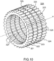
- the figure 10 shows a part 32A of the intermediate rotor 32 in a perspective view.
- the part 32A comprises four concentric rings, called stages 321 to 324, distributed along the axis Y and integral in rotation along the axis Y.
- the number of stages of the part 32A is equal to the number N of stator pads.
- the stages 321-324 are electromagnetically isolated from each other by spacers 325.
- the external surface of each ring 321-324 carries a set of teeth 326 distributed in the pitch p 1 .
- the teeth 326 of each stage 321-324 are aligned with those of the other stages.
- the inner surface of each ring 321-324 carries a set of teeth 327 distributed in the pitch p 2 .
- the teeth 327 of each stage 321-324 are aligned with those of the other stages.
- the intermediate rotor 32 comprises two parts 32A and 32B integral in rotation along the axis Y.
- the part 32B not shown, is identical to the part 32A.
- the part 32A is aligned with the ring portions 31A and 31B, and the part 32B is aligned with the ring portions 31C and 31D. More specifically, the stages 321-324 of the part 32A come respectively opposite the ring portions 311A and 311B, 312A and 312B, 313A and 313B, and 314A and 314B.
- the stages 321-324 of the part 32B respectively come opposite the ring portions 311C and 311D, 312C and 312D, 313C and 313D, and 314C and 314D.
- the intermediate rotor 32 is dimensioned so that the teeth 326 can cooperate with the teeth of the ring portions 31A-31D.
- the figure 11 shows a part 33A of the central rotor 33 in a perspective view.
- Part 33A comprises four concentric rings, called stages 331 to 334, distributed along the Y axis and integral in rotation along the Y axis. More generally, part 33A comprises as many stages as the number N of stator pads .
- the stages 331-334 are electromagnetically isolated from each other by spacers 335.
- the external surface of each ring 331-334 carries a set of teeth 336 distributed according to the pitch p 2 .
- the teeth 336 of each stage 331-334 are offset by a step p ' 2 , equal to 1 / 4.p 2 or more generally 1 / Np 2 .
- the central rotor comprises two parts 33A and 33B integral in rotation along the Y axis.
- the part 33B is identical to the part 33A.
- the part 33A comes to align with the part 32A of the intermediate rotor 32, and the part 33B comes to align with the part 32B of the intermediate rotor 32.
- the central rotor 33 is dimensioned so that the teeth 336 can cooperate with the teeth 327 of the intermediate rotor 32.
- the operation of the stepper motor 30 is thus analogous to that of the stepper motor 10 illustrated by the Figures 1 to 6 .
- the figure 12 illustrates, in a view in longitudinal section along the Y axis, the operation of the stepping motor 30 in a third feeding phase.
- the teeth of the ring portions 313A, 313B, 313C and 313D are aligned with the teeth 326 of the rings 323 of the two parts 32A and 32B of the intermediate rotor 32.
- the teeth 327 of these same rings 323 are aligned with the teeth 336 of the rings 333 of the two parts 33A and 33B of the central rotor 33.
- Field lines 41 and 42 can thus circulate between the stator 31, the intermediate rotor 32, the central rotor 33 and the permanent magnet 34.
- the stepping motor 30 could be modified without departing from the scope of the invention.
- the intermediate rotor 32 and the central rotor 33 may have only one part of N stages, and the stator 31 may have only the eight ring portions 31A and 31B. The field lines are then established between the ring portions 31A and 31B.
- the stepping motor may comprise only the ring portions 31A and 31C, or 31B and 31D. The two parts of intermediate rotor 32 and central rotor 33 are then necessary.
- the number N of stages and stator studs can take any integer value greater than or equal to 3.
- the shapes of the teeth may differ from those shown on the figures 7 to 11 .
Landscapes
- Engineering & Computer Science (AREA)
- Power Engineering (AREA)
- Connection Of Motors, Electrical Generators, Mechanical Devices, And The Like (AREA)
- Control Of Stepping Motors (AREA)
Description
- L'invention se situe dans le domaine des actionneurs mécaniques de précision. Elle concerne un moteur pas à pas à forte précision et peut notamment être utilisée dans les mécanismes d'actionnement des satellites artificiels.
- Les satellites artificiels nécessitent généralement de nombreux dispositifs d'actionnement. Ces dispositifs peuvent notamment servir à déployer des panneaux depuis une configuration de stockage vers une configuration déployée, à orienter des mécanismes de pointage dans différentes directions, ou à actionner des éléments d'instruments optiques tels que des miroirs. De manière générale, le contexte spatial impose des contraintes en termes de consommation électrique, de fiabilité, de poids et d'encombrement. De plus, les dispositifs d'actionnement doivent souvent présenter une forte précision, c'est-à-dire une faible résolution angulaire dans le cas de moteurs rotatifs. Les moteurs pas à pas sont couramment utilisés comme actionneurs mécaniques pour les applications aérospatiales. En effet, ce type de moteur présente plusieurs avantages, comme un faible frottement, une possibilité de maintien en position sans consommation électrique, et une simplicité de commande. En particulier, aucun asservissement n'est nécessaire pour maintenir une position particulière. Les moteurs pas à pas présentent en outre une faible résolution angulaire, pouvant atteindre quelques dixièmes de degrés. Cependant, une diminution de la résolution angulaire s'accompagne d'une augmentation de l'encombrement et de la masse du moteur. De plus, des résolutions angulaires plus fines peuvent être nécessaires. Une solution consiste à ajouter un réducteur mécanique en sortie du moteur pas à pas. L'introduction d'un réducteur implique néanmoins une diminution du rendement énergétique du fait des frottements qu'il implique, et une augmentation du poids et de l'encombrement. Une autre solution consiste à commander le moteur pas à pas en micropas. Cette solution nécessite une électronique plus coûteuse, et ne permet pas de maintenir un couple de maintien sans alimentation.
- Le brevet
US6700272 décrit un moteur à réluctance comprenant un stator, un rotor et un rotor intermédiaire dans lequel les dents du stator n'ont pas le même pas que les dents du rotor lui faisant face. - Le document
US2010/0066184 décrit une machine électrique rotative comprenant un stator et un rotor disposant de paires de pôles magnétiques ayant des dents réparties selon un pas régulier mais différent des pas des dents des pôles du stator. - Le brevet
FR2724783 - Un but de l'invention est notamment de remédier à tout ou partie des inconvénients précités en proposant un moteur pas à pas offrant une très faible résolution angulaire tout en présentant une conception mécanique et une commande électronique simples, un encombrement limité, et une possibilité de maintien en position sans consommation électrique. A cet effet, l'invention a pour objet un moteur pas à pas à double rotor présentant un mouvement différentiel. Plus précisément, l'invention a pour objet un moteur pas à pas comprenant :
- un stator comprenant N plots statoriques, où N est un entier supérieur ou égal à trois,
- un premier rotor apte à se déplacer par rapport au stator selon un axe, le premier rotor comprenant un premier ensemble de dents réparties selon un premier pas p1, et un deuxième ensemble de dents réparties selon un deuxième pas p2, et
- un deuxième rotor apte à se déplacer par rapport au premier rotor selon l'axe, le deuxième rotor comprenant N plots rotoriques,
- Selon une forme particulière de réalisation, les mouvements entre le stator, le premier rotor, et le deuxième rotor sont des mouvements de rotation selon l'axe.
- Chaque plot statorique peut comprendre une première portion d'anneau dont une surface intérieure est dentée avec le pas p1, les dents de la portion d'anneau étant aptes à venir s'aligner avec des dents du premier ensemble du premier rotor. Chaque plot statorique peut aussi comprendre une deuxième portion d'anneau dont une surface intérieure est dentée avec le pas p1, la deuxième portion d'anneau étant disposée symétriquement selon l'axe par rapport à la première portion d'anneau, les dents de la deuxième portion d'anneau étant aptes à venir s'aligner avec des dents du premier ensemble du premier rotor. Le premier rotor et le deuxième rotor peuvent alors comporter chacun N anneaux concentriques répartis le long de l'axe et isolés électromagnétiquement les uns des autres, les première et deuxième portions d'anneau de chaque plot statorique s'alignant avec l'un des anneaux du premier rotor et avec l'un des anneaux du deuxième rotor, de manière à permettre la circulation d'un champ magnétique entre la première portion d'anneau et la deuxième portion d'anneau.
- Selon une forme particulière de réalisation, le premier rotor comprend deux parties solidaires en rotation selon l'axe, chaque partie comportant N anneaux concentriques répartis le long de l'axe et isolés électromagnétiquement les uns des autres, une surface extérieure de chaque anneau comprenant des dents réparties selon le pas p1 et alignées entre les différents anneaux, une surface intérieure de chaque anneau comprenant des dents réparties selon le pas p2 et alignées entre les différents anneaux, le deuxième rotor comprenant deux parties solidaires en rotation selon l'axe, chaque partie du deuxième rotor comportant N anneaux concentriques répartis le long de l'axe et isolés électromagnétiquement les uns des autres, une surface extérieure de chaque anneau comprenant des dents réparties selon le pas p2 et décalées par rapport aux dents des autres anneaux du pas p'2, chaque anneau du premier rotor venant s'aligner avec l'un des anneaux du deuxième rotor.
- En outre, chaque plot statorique peut comprendre quatre portions d'anneau concentriques, chaque portion d'anneau étant dentée avec le pas p1, pour chaque plot statorique, une première portion d'anneau et une deuxième portion d'anneau étant disposées symétriquement selon l'axe et venant coopérer avec l'un des anneaux de la première partie du premier rotor et avec l'un des anneaux de la première partie du deuxième rotor, une troisième portion d'anneau et une quatrième portion d'anneau étant disposées symétriquement selon l'axe et venant coopérer avec l'un des anneaux de la deuxième partie du premier rotor et avec l'un des anneaux de la deuxième partie du deuxième rotor.
- L'invention a notamment pour avantage qu'elle permet au moteur pas à pas d'être commandé en pas plein tout en présentant un très faible mouvement angulaire entre le deuxième rotor et le stator entre deux phases d'alimentation successives.
- L'invention sera mieux comprise et d'autres avantages apparaîtront à la lecture de la description qui va suivre, faite en regard de dessins annexés sur lesquels :
- la
figure 1 représente, sous forme d'un schéma synoptique simplifié, un premier exemple de moteur pas à pas selon l'invention ; - les
figures 2 à 6 illustrent le fonctionnement du moteur pas à pas de lafigure 1 lors de différentes phases d'alimentation ; - la
figure 7 représente un deuxième exemple de moteur pas à pas selon l'invention ; - les
figures 8 et9 représentent, respectivement dans une vue en perspective et dans une vue en coupe, un stator du moteur pas à pas de lafigure 7 ; - la
figure 10 représente une partie d'un rotor intermédiaire du moteur pas à pas de lafigure 7 ; - la
figure 11 représente une partie d'un rotor central du moteur pas à pas de lafigure 7 ; - la
figure 12 illustre, dans une vue en coupe longitudinale, le fonctionnement du moteur pas à pas de lafigure 7 . - La
figure 1 représente, sous forme d'un schéma synoptique simplifié, un premier exemple de moteur pas à pas selon l'invention. Le moteur est représenté ici comme étant un moteur linéaire. Cependant, il pourrait également s'agir d'un moteur rotatif dans une représentation à plat. Le moteur pas à pas 10 représenté sur lafigure 1 comprend un stator 11, un premier rotor 12, et un deuxième rotor 13 comportant un aimant permanent 14. Le stator 11 comporte quatre plots statoriques 111 à 114. Chaque plot statorique 111-114 comprend deux dents 115 espacées l'une de l'autre d'un pas p1, et une bobine 116 pouvant être alimentée par un courant électrique afin de créer un champ électromagnétique. Les plots statoriques 111-114 sont répartis sur le stator 11 selon un pas p1(2+1/N). Plus précisément, les plots statoriques sont disposés de manière à ce que l'une des dents 115 d'un plot statorique 111-114 soit située à une distance p'1 d'un plot statorique contigu. Le pas p'1 est déterminé en fonction du pas p1 et du nombre N de plots statoriques. Il est égal à (1+1 /N).p1, soit dans l'exemple de lafigure 1 , (1+1/4).p1. Le premier rotor 12, également appelé rotor intermédiaire, est en liaison glissière par rapport au stator 11 selon un axe X (ou en liaison pivot selon un axe orthogonal à l'axe X dans le cas d'un moteur rotatif). La liaison glissière doit être entendue au sens large, c'est-à-dire que la liaison doit comprendre au moins un degré de liberté en translation selon l'axe X. Le rotor intermédiaire 12 comprend un premier ensemble de dents 121 réparties selon le pas p1 et venant en vis-à-vis des dents 115 des plots statoriques 111-114. Du fait de la différence entre les pas p1 et p'1, les dents 115 de tous les plots statoriques 111-114 ne peuvent pas venir s'aligner simultanément avec les dents 121 du rotor intermédiaire 12. À chaque pas du moteur, deux dents 121 viennent s'aligner avec les dents 115 de l'un des plots statoriques 111-114. Le rotor intermédiaire 12 comprend en outre un deuxième ensemble de dents 122 réparties selon un pas p2, différent du pas p1. Le deuxième rotor 13, également appelé rotor central, est en liaison glissière par rapport au rotor intermédiaire 12 selon l'axe X (ou en liaison pivot dans le cas d'un moteur rotatif). Il est donc également en liaison glissière par rapport au stator 11. Le rotor central 13 comprend quatre ensembles 131 à 134 de dents 135, appelés plots rotoriques, par analogie avec les plots statoriques 111-114. De manière générale, le rotor central 13 comprend N plots rotoriques, soit autant de plots rotoriques que de plots statoriques. Chaque plot rotorique 131-134 comprend deux dents 135 espacées l'une de l'autre du pas p2. Les plots rotoriques 131-134 sont répartis selon un pas p2(2+1/N). Plus précisément, les plots rotoriques sont disposés de manière à ce que l'une des dents 135 d'un plot rotorique 131-134 soit située à une distance p'2 d'un plot rotorique contigu. Le pas p'2 est déterminé en fonction du pas p2 et du nombre N de plots rotoriques et statoriques. Il est égal à (1+1/N).p2, soit dans l'exemple de lafigure 1 , (1+1/4).p2. Du fait de la différence entre les pas p2 et p'2, les dents 135 de tous les plots rotoriques 131-134 ne peuvent pas venir s'aligner simultanément avec les dents 122 du rotor intermédiaire 12. À chaque pas du moteur, deux dents 122 viennent s'aligner avec les dents 135 de l'un des plots rotoriques 131-134. L'aimant permanent 14 est accolé au rotor central 13 de manière à créer ou augmenter la circulation du courant magnétique entre les plots statoriques 111-114 et les plots rotoriques 131-134. - Les
figures 2 à 6 illustrent le fonctionnement du moteur pas à pas 10 schématisé sur lafigure 1 lors de ses phases d'alimentation successives. Une phase correspond à une période de temps pendant laquelle une bobine 116 de l'un des plots statoriques 111-114 est alimentée. La bobine elle-même peut également être appelée "phase". Durant chaque phase, le rotor intermédiaire 12 et le rotor central 13 se positionnent de manière à minimiser la réluctance entre l'un des plots statoriques 111-114 et le plot rotorique 131-134 correspondant. Lafigure 2 représente les positions respectives du stator 11, du rotor intermédiaire 12 et du rotor central 13 lors d'une première phase, en l'occurrence lorsque la bobine 116 du plot statorique 111 est alimentée. Afin de minimiser la réluctance entre le plot statorique 111 et le plot rotorique 131, deux dents 121 du rotor intermédiaire 12 viennent s'aligner avec les dents 115 du plot statorique 111, et deux dents 122 du rotor intermédiaire 12 viennent s'aligner avec les dents 135 du plot rotorique 131. Le champ magnétique 20 établi entre le plot statorique 111 et le plot rotorique 131 est alors maximal. - La
figure 3 représente le moteur pas à pas 10 lors de la deuxième phase, c'est-à-dire lorsque la bobine 116 du deuxième plot statorique 112 est alimentée. Les positions du rotor intermédiaire 12 et du rotor central 13 lors de la première phase sont représentées en traits interrompus. Afin de minimiser la réluctance entre le plot statorique 112 et le plot rotorique 132, deux dents 121 du rotor intermédiaire 12 viennent s'aligner avec les dents 115 du plot statorique 112, et deux dents 122 du rotor intermédiaire 12 viennent s'aligner avec les dents 135 du plot rotorique 132. De manière classique, le passage du premier alignement entre les dents 115 du plot statorique 111 et les dents 121 du rotor intermédiaire 12, au deuxième alignement entre les dents 115 du plot statorique 112 et les dents 121 du rotor intermédiaire 12 entraîne un déplacement du rotor intermédiaire 12 par rapport au stator 11 d'une distance d1 égale à p1/N, soit ici p1/4. De manière analogue, le passage du premier alignement entre les dents 122 du rotor intermédiaire 12 et les dents 135 du plot rotorique 131, au deuxième alignement entre les dents 122 du rotor intermédiaire 12 et les dents 135 du plot rotorique 132 entraîne un déplacement du rotor central 13 par rapport au rotor intermédiaire 12 d'une distance d2 égale à p2/N, soit ici p2/4. Dans la mesure où la différence entre les pas p1 et p2 est relativement faible, le rotor intermédiaire 12 est entraîné dans un premier sens S1, et le rotor central 13 est entraîné dans un deuxième sens S2, opposé au premier. Ainsi, le mouvement résultant du rotor central 13 par rapport au stator 11 est inférieur à chacun des deux mouvements relatifs. La distance d3 parcourue par le rotor central 13 par rapport au stator 11 est égale à la distance (d2-d1), c'est-à-dire (p2-p1)/N. Il s'ensuit que la distance d3 peut être choisie aussi réduite qu'on le souhaite en choisissant des valeurs de pas p1 et p2 appropriées. - La
figure 4 représente le moteur pas à pas 10 lors de la troisième phase, c'est-à-dire lorsque la bobine 116 du troisième plot statorique 113 est alimentée. Le rotor intermédiaire 12 et le rotor central 13 sont encore représentés en traits interrompus dans les positions qu'ils occupaient lors de la première phase. Lors de cette troisième phase, ce sont les dents 115 du plot statorique 113 qui viennent s'aligner avec des dents 121 du rotor intermédiaire 12, et les dents 135 du plot rotorique 133 qui viennent s'aligner avec des dents 122 du rotor intermédiaire 12. Le passage des alignements de la deuxième phase aux alignements de la troisième phase entraîne un nouveau déplacement du rotor intermédiaire 12 par rapport au stator 11 de distance d1 et de sens S1, et un nouveau déplacement du rotor central 13 par rapport au rotor intermédiaire 12 de distance d2 et de sens S2. Le rotor central 13 a donc subi un déplacement égal à 2.(d2-d1) depuis la première phase. - La
figure 5 représente le moteur pas à pas 10 lors de la quatrième phase, c'est-à-dire lorsque la bobine 116 du quatrième plot statorique 114 est alimentée. Dans cette phase, les dents 115 du plot statorique 114 viennent s'aligner avec des dents 121 du rotor intermédiaire 12, et les dents 135 du plot rotorique 134 viennent s'aligner avec des dents 122 du rotor intermédiaire 12. Le passage des alignements de la troisième phase aux alignements de la troisième phase entraîne un nouveau déplacement du rotor intermédiaire 12 par rapport au stator 11 de distance d1 et de sens S1, et un nouveau déplacement du rotor central 13 par rapport au rotor intermédiaire 12 de distance d2 et de sens S2. Le rotor central 13 a donc subi un déplacement égal à 3.(d2-d1) depuis la première phase. - La
figure 6 représente le moteur pas à pas 10 lors de la cinquième phase. Cette phase correspond en fait à la première phase, dans laquelle la bobine du premier plot statorique 111 est alimentée. Les mêmes alignements que ceux de la première phase sont obtenus. Les passages successifs de la première à la cinquième phase ont ainsi entraîné un déplacement du rotor intermédiaire 12 par rapport au stator 11 de distance p1 - soit 4.d1 - et de sens S1, et un déplacement du rotor central 13 par rapport au rotor intermédiaire 12 de distance p2 - soit 4.d2 - et de sens S2. En conséquence, le déplacement du rotor central 13 par rapport au stator 11 est égal à p2-p1. - L'exemple de réalisation du moteur pas à pas de la
figure 1 peut être généralisé. En particulier, comme indiqué précédemment, l'invention peut être appliquée aux moteurs pas à pas rotatifs. Dans un tel cas, les mouvements des rotors sont des mouvements de rotation, et les pas considérés sont des pas angulaires. Par ailleurs, il a été considéré un nombre N de plots rotoriques et de plots statoriques égal à quatre. Le nombre N peut cependant prendre toute valeur entière supérieure ou égale à trois. De manière générale, chaque plot statorique et chaque plot rotorique peut comprendre une ou plusieurs dents. Avec a un entier représentant le nombre de dents de chaque plot statorique, les plots statoriques sont répartis sur le stator selon un pas égal à p1(a+1/N). De même, avec b un entier représentant le nombre de dents de chaque plot rotorique, les plots rotoriques sont répartis sur le rotor selon un pas égal à p2(b+1/N). De préférence, les plots rotoriques et statoriques comprennent le même nombre de dents. Lorsqu'un plot comprend une pluralité de dents, ces dents sont réparties selon le pas p1 ou p2, selon qu'il s'agit d'un plot statorique ou rotorique, respectivement. Chaque dent positionnée à l'extrémité de la pluralité de dents d'un plot statorique doit être à la distance p'1 de l'une des dents d'un plot statorique consécutif. De même, chaque dent positionnée à l'extrémité de la pluralité de dents d'un plot rotorique doit être à la distance p'2 de l'une des dents d'un plot rotorique consécutif. Les pas p'1 et p'2 ont été indiqués comme étant égaux à (1+1/N).p1 et (1+1/N).p2, respectivement. Néanmoins, du fait de la périodicité des dents du rotor intermédiaire et du rotor central, ces pas peuvent aussi être égaux à p1/N et p2/N, respectivement. Les dents du stator, du rotor intermédiaire et du rotor central ont été schématisées dans lesfigures 1 à 6 sous forme de triangles. Néanmoins, toute autre forme de dents peut être utilisée dans le cadre de l'invention. Plus généralement, les dents peuvent être remplacées par tout moyen apte à générer des positions présentant une réluctance inférieure à celle des autres positions. En particulier, des matériaux dont les propriétés électromagnétiques diffèrent peuvent être utilisés. À titre d'exemple, le pas p2 peut être égal à 1,1 fois le pas p1. La différence entre les pas p1 et p2 peut être ajustée en fonction de la résolution angulaire souhaitée entre le stator et le rotor central. - La
figure 7 représente un deuxième exemple de réalisation d'un moteur pas à pas selon l'invention. Il s'agit ici d'un moteur pas à pas rotatif à reluctance variable et à rotors étagés. Le moteur pas à pas 30 comprend un stator 31, un rotor intermédiaire 32, et un rotor central 33 comportant un aimant permanent 34. L'aimant permanent 34 est solidaire du rotor central 33. Les rotors 32 et 33 sont en liaison pivot par rapport au stator 31 selon un axe Y. - Les
figures 8 et9 représentent le stator 31 du moteur 30 de lafigure 7 dans une vue en perspective et dans une vue en coupe selon l'axe Y, respectivement. Le stator 31 comprend quatre plots statoriques 311, 312, 313 et 314. Chaque plot statorique 311-314 comporte respectivement quatre portions d'anneau 311A-311D, 312A-312D, 313A-313D et 314A-314D. Ces portions d'anneau sont notées de manière générique 31A-31D. Chaque portion d'anneau 31C est décalée en translation selon l'axe Y de la portion d'anneau correspondante 31A. Les portions d'anneau 31B et 31D sont positionnées en regard de chaque portion d'anneau 31A et 31C, respectivement. Chaque portion d'anneau est dentée avec un même pas p1. Les dents de la portion d'anneau 312A sont décalées angulairement des dents de la portion d'anneau 311A d'un pas p'1. Le pas p'1 est égal à 1/4.p1. Plus généralement le décalage angulaire est égal à 1/N.p1, où N est le nombre de plots statoriques. De même, les dents des portions d'anneau 313A et 314A sont décalées angulairement des dents des portions d'anneau 312A et 313A, respectivement, du pas p'1. Il en va de même pour les portions d'anneau 311B-314B, 311C-314C, et 311D-314D. Les dents des portions d'anneau 31A sont alignées avec les dents des portions d'anneau respectives 31C, et les dents des portions d'anneau 31B sont alignées avec les dents des portions d'anneau 31D. Le stator comprend en outre huit bobines 316 alimentées par paire. Une première bobine 316 permet d'alimenter les portions d'anneau 311A et 311C. Une deuxième bobine 316 permet d'alimenter les portions d'anneau 311B et 311D. De manière analogue, les six autres bobines permettent d'alimenter individuellement les portions d'anneau 312A et 312C, 312B et 312D, 313A et 313C, 313B et 313D, 314A et 314C, et 314B et 314D. - La
figure 10 représente une partie 32A du rotor intermédiaire 32 dans une vue en perspective. La partie 32A comprend quatre anneaux concentriques, appelés étages 321 à 324, répartis le long de l'axe Y et solidaires en rotation selon l'axe Y. Le nombre d'étages de la partie 32A est égal au nombre N de plots statoriques. Les étages 321-324 sont isolés électromagnétiquement les uns des autres par des entretoises 325. La surface extérieure de chaque anneau 321-324 porte un ensemble de dents 326 réparties selon le pas p1. Les dents 326 de chaque étage 321-324 sont alignées avec celles des autres étages. La surface intérieure de chaque anneau 321-324 porte un ensemble de dents 327 réparties selon le pas p2. Les dents 327 de chaque étage 321-324 sont alignées avec celles des autres étages. Le rotor intermédiaire 32 comprend deux parties 32A et 32B solidaires en rotation selon l'axe Y. La partie 32B, non représentée, est identique à la partie 32A. La partie 32A vient s'aligner avec les portions d'anneau 31A et 31B, et la partie 32B vient s'aligner avec les portions d'anneau 31C et 31D. Plus précisément, les étages 321-324 de la partie 32A viennent respectivement en vis-à-vis des portions d'anneaux 311A et 311B, 312A et 312B, 313A et 313B, et 314A et 314B. Les étages 321-324 de la partie 32B viennent respectivement en vis-à-vis des portions d'anneau 311C et 311D, 312C et 312D, 313C et 313D, et 314C et 314D. Le rotor intermédiaire 32 est dimensionné de manière à ce que les dents 326 puissent coopérer avec les dents des portions d'anneau 31A-31D. - La
figure 11 représente une partie 33A du rotor central 33 dans une vue en perspective. La partie 33A comprend quatre anneaux concentriques, appelés étages 331 à 334, répartis le long de l'axe Y et solidaires en rotation selon l'axe Y. Plus généralement, la partie 33A comprend autant d'étages que le nombre N de plots statoriques. Les étages 331-334 sont isolés électromagnétiquement les uns des autres par des entretoises 335. La surface extérieure de chaque anneau 331-334 porte un ensemble de dents 336 réparties selon le pas p2. Les dents 336 de chaque étage 331-334 sont décalées d'un pas p'2, égal à 1/4.p2 ou, plus généralement, 1/N.p2. Le rotor central comprend deux parties 33A et 33B solidaires en rotation selon l'axe Y. La partie 33B, non représentée, est identique à la partie 33A. La partie 33A vient s'aligner avec la partie 32A du rotor intermédiaire 32, et la partie 33B vient s'aligner avec la partie 32B du rotor intermédiaire 32. Le rotor central 33 est dimensionné de manière à ce que les dents 336 puissent coopérer avec les dents 327 du rotor intermédiaire 32. Le fonctionnement du moteur pas à pas 30 est ainsi analogue à celui du moteur pas à pas 10 illustré par lesfigures 1 à 6 . - La
figure 12 illustre, dans une vue en coupe longitudinale selon l'axe Y, le fonctionnement du moteur pas à pas 30 dans une troisième phase d'alimentation. Dans cette phase, les dents des portions d'anneau 313A, 313B, 313C et 313D sont alignées avec les dents 326 des anneaux 323 des deux parties 32A et 32B du rotor intermédiaire 32. En outre, les dents 327 de ces mêmes anneaux 323 sont alignées avec les dents 336 des anneaux 333 des deux parties 33A et 33B du rotor central 33. Des lignes de champ 41 et 42 peuvent ainsi circuler entre le stator 31, le rotor intermédiaire 32, le rotor central 33 et l'aimant permanent 34. - À la lecture de la
figure 12 , on comprend que le moteur pas à pas 30 pourrait être modifié sans sortir du cadre de l'invention. Par exemple, le rotor intermédiaire 32 et le rotor central 33 peuvent ne comporter qu'une seule partie de N étages, et le stator 31 peut ne comporter que les huit portions d'anneau 31A et 31B. Les lignes de champ s'établissent alors entre les portions d'anneau 31A et 31B. À l'inverse, le moteur pas à pas peut ne comporter que les portions d'anneau 31A et 31C, ou 31B et 31D. Les deux parties de rotor intermédiaire 32 et de rotor central 33 sont alors nécessaires. Par ailleurs, le nombre N d'étages et de plots statoriques peut prendre toute valeur entière supérieure ou égale à 3. De plus les formes des dents peuvent différer de celles représentées sur lesfigures 7 à 11 .
les N plots rotoriques comprenant une pluralité b de dents réparties selon le pas p2, où b est un entier, les N plots rotoriques étant répartis sur le deuxième rotor selon un quatrième pas égal à p2(b+1/N) et étant aptes à venir s'aligner individuellement avec l'une des dents du deuxième ensemble, le passage d'un alignement à un alignement consécutif entraînant un déplacement du deuxième rotor par rapport au premier rotor dans un deuxième sens, opposé au premier, avec le pas p2/N.
Claims (7)
- Moteur pas à pas comprenant :• un stator (11, 31) comprenant N plots statoriques (111-114, 311-314), où N est un entier supérieur ou égal à trois,• un premier rotor (12, 32) apte à se déplacer par rapport au stator (11, 31) selon un axe (X, Y), le premier rotor (12, 32) comprenant un premier ensemble de dents (121) réparties selon un premier pas p1, et un deuxième ensemble de dents (122) réparties selon un deuxième pas p2, et• un deuxième rotor (13, 33) apte à se déplacer par rapport au premier rotor (12, 32) selon l'axe (X, Y), le deuxième rotor (13, 33) comprenant N plots rotoriques (131-134, 311-314),caractérisé en ce que
les N plots statoriques (111-114, 311-314) comprenant une pluralité a de dents réparties selon le pas p1, où a est un entier représentant le nombre de dents de chaque plot statorique, les N plots statoriques (111-114, 311-314) étant répartis sur le stator (11, 31) selon un troisième pas égal à p1(a+1/N), les dents (121) du premier ensemble étant aptes à venir s'aligner individuellement avec l'un des plots statoriques (111-114, 311-314), le passage d'un alignement à un alignement consécutif entraînant un déplacement du premier rotor (12, 32) par rapport au stator (11, 31) dans un premier sens (S1) avec le pas p1/N,
et en ce que
les N plots rotoriques (131-134, 311-314) comprenant une pluralité b de dents réparties selon le pas p2, où b est un entier représentant le nombre de dents de chaque plot rotorique, les N plots rotoriques (131-134, 311-314) étant répartis sur le deuxième rotor (13, 33) selon un quatrième pas égal à p2(b+1/N) et étant aptes à venir s'aligner individuellement avec l'une des dents (122) du deuxième ensemble, le passage d'un alignement à un alignement consécutif entraînant un déplacement du deuxième rotor (13, 33) par rapport au premier rotor (12, 32) dans un deuxième sens (S2), opposé au premier, avec le pas p2/N. - Moteur pas à pas selon la revendication 1, dont le troisième pas et le quatrième pas ont une même valeur, et dont les mouvements entre le stator (31), le premier rotor (32), et le deuxième rotor (33) sont des mouvements de rotation selon l'axe (Y).
- Moteur pas à pas selon la revendication 2, dans lequel chaque plot statorique (311-314) comprend une première portion d'anneau (31A) dont une surface intérieure est dentée avec le pas p1, les dents de la portion d'anneau étant aptes à venir s'aligner avec des dents (326) du premier ensemble du premier rotor (32).
- Moteur pas à pas selon la revendication 3, dans lequel chaque plot statorique (311-314) comprend une deuxième portion d'anneau (31B) dont une surface intérieure est dentée avec le pas p1, la deuxième portion d'anneau (31B) étant disposée symétriquement selon l'axe (Y) par rapport à la première portion d'anneau (31A), les dents de la deuxième portion d'anneau (31B) étant aptes à venir s'aligner avec des dents (326) du premier ensemble du premier rotor (32).
- Moteur pas à pas selon la revendication 4, dans lequel le premier rotor (32) et le deuxième rotor (33) comportent chacun N anneaux concentriques (321-324, 331-334) répartis le long de l'axe (Y) et isolés électromagnétiquement les uns des autres, les première et deuxième portions d'anneau (31A, 31B) de chaque plot statorique (311-314) s'alignant avec l'un des anneaux (321-324) du premier rotor (32) et avec l'un des anneaux (331-334) du deuxième rotor (33), de manière à permettre la circulation d'un champ magnétique entre la première portion d'anneau (31A) et la deuxième portion d'anneau (31B).
- Moteur pas à pas selon la revendication 2, dans lequel le premier rotor (32) comprend deux parties (32A, 32B) solidaires en rotation selon l'axe (Y), chaque partie comportant N anneaux concentriques (321-324) répartis le long de l'axe (Y) et isolés électromagnétiquement les uns des autres, une surface extérieure de chaque anneau comprenant des dents réparties selon le pas p1 et alignées entre les différents anneaux, une surface intérieure de chaque anneau comprenant des dents réparties selon le pas p2 et alignées entre les différents anneaux, le deuxième rotor (33) comprenant deux parties (33A, 33B) solidaires en rotation selon l'axe (Y), chaque partie du deuxième rotor comportant N anneaux concentriques (331-334) répartis le long de l'axe (Y) et isolés électromagnétiquement les uns des autres, une surface extérieure de chaque anneau comprenant des dents réparties selon le pas p2 et décalées par rapport aux dents des autres anneaux du pas p'2, chaque anneau (321-324) du premier rotor (32) venant s'aligner avec l'un des anneaux (331-334) du deuxième rotor (33).
- Moteur pas à pas selon la revendication 6, dans lequel chaque plot statorique (311-314) comprend quatre portions d'anneau (31A-31D) concentriques, chaque portion d'anneau étant dentée avec le pas p1, pour chaque plot statorique, une première portion d'anneau (31A) et une deuxième portion d'anneau (31B) étant disposées symétriquement selon l'axe (Y) et venant coopérer avec l'un des anneaux (321-324) de la première partie (32A) du premier rotor (32) et avec l'un des anneaux (331-334) de la première partie (33A) du deuxième rotor (33), une troisième portion d'anneau (31B) et une quatrième portion d'anneau (31D) étant disposées symétriquement selon l'axe (Y) et venant coopérer avec l'un des anneaux (321-324) de la deuxième partie (32B) du premier rotor (32) et avec l'un des anneaux (331-334) de la deuxième partie (33B) du deuxième rotor (33).
Applications Claiming Priority (1)
| Application Number | Priority Date | Filing Date | Title |
|---|---|---|---|
| FR1203295A FR2999036B1 (fr) | 2012-12-05 | 2012-12-05 | Moteur pas a pas a double rotor |
Publications (2)
| Publication Number | Publication Date |
|---|---|
| EP2741406A1 EP2741406A1 (fr) | 2014-06-11 |
| EP2741406B1 true EP2741406B1 (fr) | 2020-01-22 |
Family
ID=47878120
Family Applications (1)
| Application Number | Title | Priority Date | Filing Date |
|---|---|---|---|
| EP13195544.5A Active EP2741406B1 (fr) | 2012-12-05 | 2013-12-03 | Moteur pas à pas à double rotor |
Country Status (6)
| Country | Link |
|---|---|
| US (1) | US9318941B2 (fr) |
| EP (1) | EP2741406B1 (fr) |
| JP (1) | JP6317096B2 (fr) |
| CA (1) | CA2835793C (fr) |
| ES (1) | ES2780384T3 (fr) |
| FR (1) | FR2999036B1 (fr) |
Cited By (1)
| Publication number | Priority date | Publication date | Assignee | Title |
|---|---|---|---|---|
| FR3157713A1 (fr) * | 2023-12-21 | 2025-06-27 | Safran Electronics & Defense | Moteur pas-à-pas à denture d’engrenage et procédé de fabrication. |
Families Citing this family (2)
| Publication number | Priority date | Publication date | Assignee | Title |
|---|---|---|---|---|
| US9667126B2 (en) * | 2015-01-05 | 2017-05-30 | Langham Automatic Co., Ltd. | Motor |
| GB2560988A (en) * | 2017-03-31 | 2018-10-03 | Kenwood Ltd | Kitchen appliance and apparatus therefor |
Family Cites Families (12)
| Publication number | Priority date | Publication date | Assignee | Title |
|---|---|---|---|---|
| DE1158624B (de) * | 1960-02-22 | 1963-12-05 | Fuji Tsushinki Seizo Kabushiki | Schrittschaltmotor |
| US3801842A (en) * | 1972-06-27 | 1974-04-02 | Ncr | Stepping motor |
| JPH078130B2 (ja) * | 1986-09-20 | 1995-01-30 | 日本電信電話株式会社 | パルスモ−タ |
| US5128570A (en) * | 1991-06-24 | 1992-07-07 | Japan Servo Co., Ltd. | Permanent magnet type stepping motor |
| JP3182196B2 (ja) * | 1992-02-27 | 2001-07-03 | オリエンタルモーター株式会社 | 3相ハイブリッド形ステッピングモータ |
| FR2724783B1 (fr) * | 1994-09-19 | 1998-04-24 | Moving Magnet Tech | Micro-moteur pas a pas multipolaire |
| JPH1023731A (ja) * | 1996-07-01 | 1998-01-23 | Tamagawa Seiki Co Ltd | ハイブリッド型ステップモータを用いた駆動車輪 |
| US6700272B1 (en) * | 1997-09-30 | 2004-03-02 | Emf 97 Elektro-Maschinen-Vertrieb-Magnettechnik- Und Forschungs Gmbh | Reluctance motor with gearless step-down without electronic control of rotating field |
| US6548923B2 (en) * | 2000-03-29 | 2003-04-15 | Japan Servo Co., Ltd. | Two-phase hybrid type stepping motor |
| JP4309325B2 (ja) * | 2004-10-05 | 2009-08-05 | 日本電産サーボ株式会社 | 複合3相ハイブリッド型回転電機およびその駆動方法 |
| JP5008462B2 (ja) * | 2007-05-31 | 2012-08-22 | 日本電産サーボ株式会社 | ハイブリッド式永久磁石回転電機 |
| JP5643471B2 (ja) * | 2007-10-19 | 2014-12-17 | 沖マイクロ技研株式会社 | ステッピングモータ |
-
2012
- 2012-12-05 FR FR1203295A patent/FR2999036B1/fr not_active Expired - Fee Related
-
2013
- 2013-12-02 US US14/094,399 patent/US9318941B2/en active Active
- 2013-12-03 CA CA2835793A patent/CA2835793C/fr active Active
- 2013-12-03 ES ES13195544T patent/ES2780384T3/es active Active
- 2013-12-03 EP EP13195544.5A patent/EP2741406B1/fr active Active
- 2013-12-05 JP JP2013252142A patent/JP6317096B2/ja active Active
Non-Patent Citations (1)
| Title |
|---|
| None * |
Cited By (1)
| Publication number | Priority date | Publication date | Assignee | Title |
|---|---|---|---|---|
| FR3157713A1 (fr) * | 2023-12-21 | 2025-06-27 | Safran Electronics & Defense | Moteur pas-à-pas à denture d’engrenage et procédé de fabrication. |
Also Published As
| Publication number | Publication date |
|---|---|
| EP2741406A1 (fr) | 2014-06-11 |
| JP2014117151A (ja) | 2014-06-26 |
| CA2835793C (fr) | 2020-04-21 |
| FR2999036B1 (fr) | 2016-02-12 |
| CA2835793A1 (fr) | 2014-06-05 |
| JP6317096B2 (ja) | 2018-04-25 |
| US9318941B2 (en) | 2016-04-19 |
| FR2999036A1 (fr) | 2014-06-06 |
| ES2780384T3 (es) | 2020-08-25 |
| US20140152129A1 (en) | 2014-06-05 |
Similar Documents
| Publication | Publication Date | Title |
|---|---|---|
| FR2677507A1 (fr) | Moteur pas-a-pas ou synchrone economique. | |
| FR2695968A1 (fr) | Dispositif à palier magnétique et à butée mécanique pour le positionnement d'un corps tournant par rapport à un corps statorique. | |
| EP2741406B1 (fr) | Moteur pas à pas à double rotor | |
| WO2013124225A1 (fr) | Actionneur inertiel magnetohydrodynamique | |
| FR2696057A1 (fr) | Moteur-couple allongé et dispositif de commande en débattement angulaire le comportant. | |
| EP3363099A1 (fr) | Actionneur electromecanique pour commandes de vol electriques d'un aeronef | |
| EP2451059B1 (fr) | Moteur électromagnétique sans balai | |
| EP3120445B1 (fr) | Machine electrique hybride | |
| EP2706267B1 (fr) | Dispositif de positionnement angulaire comprenant deux ensembles mécaniques de transmission de mouvement imbriqués à deux points morts chacun | |
| CH704949B1 (fr) | Moteur pas-à-pas. | |
| EP2710714B1 (fr) | Turbine génératrice de courant électrique | |
| EP0312464B1 (fr) | Machine électrique notamment à entrefers radiaux | |
| EP0790540B1 (fr) | Transducteur électromécanique à aimants permanents multipolaires | |
| FR2839215A1 (fr) | Moteur pas a pas a stators multiples | |
| FR2743217A1 (fr) | Accelarateur ou actionneur lineaire | |
| EP4650885A1 (fr) | Dispositif de commande d'un moteur pas-à-pas pour mouvement horloger électronique | |
| FR2606225A1 (fr) | Actionneur electromagnetique a deux entrefers | |
| FR3099859A1 (fr) | Machine électrique pour une hybridation d’un aéronef | |
| FR2998738A1 (fr) | Convertisseur d'energie comportant des aimants | |
| EP3852252A1 (fr) | Dispositif d'entrainement rotatif electromagnetique | |
| FR3106449A1 (fr) | Machine électrique à flux transverse à aimants permanents au stator | |
| WO2018122829A1 (fr) | Machine électrique tournante | |
| JP2021164231A (ja) | 光モータ | |
| FR2696059A1 (fr) | Moteur-couple à induit plat et dispositif de commande en débattement angulaire le comportant. | |
| WO2009016023A1 (fr) | Moteur biphase avec un rotor a aimant multipolaire, en particulier pour l'entraînement de l'indicateur d'un affichage analogique |
Legal Events
| Date | Code | Title | Description |
|---|---|---|---|
| PUAI | Public reference made under article 153(3) epc to a published international application that has entered the european phase |
Free format text: ORIGINAL CODE: 0009012 |
|
| 17P | Request for examination filed |
Effective date: 20131203 |
|
| AK | Designated contracting states |
Kind code of ref document: A1 Designated state(s): AL AT BE BG CH CY CZ DE DK EE ES FI FR GB GR HR HU IE IS IT LI LT LU LV MC MK MT NL NO PL PT RO RS SE SI SK SM TR |
|
| AX | Request for extension of the european patent |
Extension state: BA ME |
|
| R17P | Request for examination filed (corrected) |
Effective date: 20141007 |
|
| RBV | Designated contracting states (corrected) |
Designated state(s): AL AT BE BG CH CY CZ DE DK EE ES FI FR GB GR HR HU IE IS IT LI LT LU LV MC MK MT NL NO PL PT RO RS SE SI SK SM TR |
|
| GRAP | Despatch of communication of intention to grant a patent |
Free format text: ORIGINAL CODE: EPIDOSNIGR1 |
|
| STAA | Information on the status of an ep patent application or granted ep patent |
Free format text: STATUS: GRANT OF PATENT IS INTENDED |
|
| INTG | Intention to grant announced |
Effective date: 20190802 |
|
| GRAS | Grant fee paid |
Free format text: ORIGINAL CODE: EPIDOSNIGR3 |
|
| GRAA | (expected) grant |
Free format text: ORIGINAL CODE: 0009210 |
|
| STAA | Information on the status of an ep patent application or granted ep patent |
Free format text: STATUS: THE PATENT HAS BEEN GRANTED |
|
| RAP1 | Party data changed (applicant data changed or rights of an application transferred) |
Owner name: THALES |
|
| AK | Designated contracting states |
Kind code of ref document: B1 Designated state(s): AL AT BE BG CH CY CZ DE DK EE ES FI FR GB GR HR HU IE IS IT LI LT LU LV MC MK MT NL NO PL PT RO RS SE SI SK SM TR |
|
| REG | Reference to a national code |
Ref country code: GB Ref legal event code: FG4D Free format text: NOT ENGLISH |
|
| REG | Reference to a national code |
Ref country code: CH Ref legal event code: EP |
|
| REG | Reference to a national code |
Ref country code: DE Ref legal event code: R096 Ref document number: 602013065256 Country of ref document: DE |
|
| REG | Reference to a national code |
Ref country code: AT Ref legal event code: REF Ref document number: 1227583 Country of ref document: AT Kind code of ref document: T Effective date: 20200215 |
|
| REG | Reference to a national code |
Ref country code: IE Ref legal event code: FG4D Free format text: LANGUAGE OF EP DOCUMENT: FRENCH |
|
| REG | Reference to a national code |
Ref country code: NL Ref legal event code: FP |
|
| REG | Reference to a national code |
Ref country code: LT Ref legal event code: MG4D |
|
| PG25 | Lapsed in a contracting state [announced via postgrant information from national office to epo] |
Ref country code: RS Free format text: LAPSE BECAUSE OF FAILURE TO SUBMIT A TRANSLATION OF THE DESCRIPTION OR TO PAY THE FEE WITHIN THE PRESCRIBED TIME-LIMIT Effective date: 20200122 Ref country code: PT Free format text: LAPSE BECAUSE OF FAILURE TO SUBMIT A TRANSLATION OF THE DESCRIPTION OR TO PAY THE FEE WITHIN THE PRESCRIBED TIME-LIMIT Effective date: 20200614 Ref country code: NO Free format text: LAPSE BECAUSE OF FAILURE TO SUBMIT A TRANSLATION OF THE DESCRIPTION OR TO PAY THE FEE WITHIN THE PRESCRIBED TIME-LIMIT Effective date: 20200422 Ref country code: FI Free format text: LAPSE BECAUSE OF FAILURE TO SUBMIT A TRANSLATION OF THE DESCRIPTION OR TO PAY THE FEE WITHIN THE PRESCRIBED TIME-LIMIT Effective date: 20200122 |
|
| REG | Reference to a national code |
Ref country code: ES Ref legal event code: FG2A Ref document number: 2780384 Country of ref document: ES Kind code of ref document: T3 Effective date: 20200825 |
|
| PG25 | Lapsed in a contracting state [announced via postgrant information from national office to epo] |
Ref country code: BG Free format text: LAPSE BECAUSE OF FAILURE TO SUBMIT A TRANSLATION OF THE DESCRIPTION OR TO PAY THE FEE WITHIN THE PRESCRIBED TIME-LIMIT Effective date: 20200422 Ref country code: GR Free format text: LAPSE BECAUSE OF FAILURE TO SUBMIT A TRANSLATION OF THE DESCRIPTION OR TO PAY THE FEE WITHIN THE PRESCRIBED TIME-LIMIT Effective date: 20200423 Ref country code: HR Free format text: LAPSE BECAUSE OF FAILURE TO SUBMIT A TRANSLATION OF THE DESCRIPTION OR TO PAY THE FEE WITHIN THE PRESCRIBED TIME-LIMIT Effective date: 20200122 Ref country code: IS Free format text: LAPSE BECAUSE OF FAILURE TO SUBMIT A TRANSLATION OF THE DESCRIPTION OR TO PAY THE FEE WITHIN THE PRESCRIBED TIME-LIMIT Effective date: 20200522 Ref country code: SE Free format text: LAPSE BECAUSE OF FAILURE TO SUBMIT A TRANSLATION OF THE DESCRIPTION OR TO PAY THE FEE WITHIN THE PRESCRIBED TIME-LIMIT Effective date: 20200122 Ref country code: LV Free format text: LAPSE BECAUSE OF FAILURE TO SUBMIT A TRANSLATION OF THE DESCRIPTION OR TO PAY THE FEE WITHIN THE PRESCRIBED TIME-LIMIT Effective date: 20200122 |
|
| REG | Reference to a national code |
Ref country code: DE Ref legal event code: R097 Ref document number: 602013065256 Country of ref document: DE |
|
| PG25 | Lapsed in a contracting state [announced via postgrant information from national office to epo] |
Ref country code: DK Free format text: LAPSE BECAUSE OF FAILURE TO SUBMIT A TRANSLATION OF THE DESCRIPTION OR TO PAY THE FEE WITHIN THE PRESCRIBED TIME-LIMIT Effective date: 20200122 Ref country code: SK Free format text: LAPSE BECAUSE OF FAILURE TO SUBMIT A TRANSLATION OF THE DESCRIPTION OR TO PAY THE FEE WITHIN THE PRESCRIBED TIME-LIMIT Effective date: 20200122 Ref country code: CZ Free format text: LAPSE BECAUSE OF FAILURE TO SUBMIT A TRANSLATION OF THE DESCRIPTION OR TO PAY THE FEE WITHIN THE PRESCRIBED TIME-LIMIT Effective date: 20200122 Ref country code: LT Free format text: LAPSE BECAUSE OF FAILURE TO SUBMIT A TRANSLATION OF THE DESCRIPTION OR TO PAY THE FEE WITHIN THE PRESCRIBED TIME-LIMIT Effective date: 20200122 Ref country code: RO Free format text: LAPSE BECAUSE OF FAILURE TO SUBMIT A TRANSLATION OF THE DESCRIPTION OR TO PAY THE FEE WITHIN THE PRESCRIBED TIME-LIMIT Effective date: 20200122 Ref country code: EE Free format text: LAPSE BECAUSE OF FAILURE TO SUBMIT A TRANSLATION OF THE DESCRIPTION OR TO PAY THE FEE WITHIN THE PRESCRIBED TIME-LIMIT Effective date: 20200122 Ref country code: SM Free format text: LAPSE BECAUSE OF FAILURE TO SUBMIT A TRANSLATION OF THE DESCRIPTION OR TO PAY THE FEE WITHIN THE PRESCRIBED TIME-LIMIT Effective date: 20200122 |
|
| REG | Reference to a national code |
Ref country code: AT Ref legal event code: MK05 Ref document number: 1227583 Country of ref document: AT Kind code of ref document: T Effective date: 20200122 |
|
| PLBE | No opposition filed within time limit |
Free format text: ORIGINAL CODE: 0009261 |
|
| STAA | Information on the status of an ep patent application or granted ep patent |
Free format text: STATUS: NO OPPOSITION FILED WITHIN TIME LIMIT |
|
| 26N | No opposition filed |
Effective date: 20201023 |
|
| PG25 | Lapsed in a contracting state [announced via postgrant information from national office to epo] |
Ref country code: AT Free format text: LAPSE BECAUSE OF FAILURE TO SUBMIT A TRANSLATION OF THE DESCRIPTION OR TO PAY THE FEE WITHIN THE PRESCRIBED TIME-LIMIT Effective date: 20200122 |
|
| PG25 | Lapsed in a contracting state [announced via postgrant information from national office to epo] |
Ref country code: PL Free format text: LAPSE BECAUSE OF FAILURE TO SUBMIT A TRANSLATION OF THE DESCRIPTION OR TO PAY THE FEE WITHIN THE PRESCRIBED TIME-LIMIT Effective date: 20200122 Ref country code: SI Free format text: LAPSE BECAUSE OF FAILURE TO SUBMIT A TRANSLATION OF THE DESCRIPTION OR TO PAY THE FEE WITHIN THE PRESCRIBED TIME-LIMIT Effective date: 20200122 |
|
| REG | Reference to a national code |
Ref country code: CH Ref legal event code: PL |
|
| PG25 | Lapsed in a contracting state [announced via postgrant information from national office to epo] |
Ref country code: MC Free format text: LAPSE BECAUSE OF FAILURE TO SUBMIT A TRANSLATION OF THE DESCRIPTION OR TO PAY THE FEE WITHIN THE PRESCRIBED TIME-LIMIT Effective date: 20200122 |
|
| REG | Reference to a national code |
Ref country code: BE Ref legal event code: MM Effective date: 20201231 |
|
| PG25 | Lapsed in a contracting state [announced via postgrant information from national office to epo] |
Ref country code: LU Free format text: LAPSE BECAUSE OF NON-PAYMENT OF DUE FEES Effective date: 20201203 Ref country code: IE Free format text: LAPSE BECAUSE OF NON-PAYMENT OF DUE FEES Effective date: 20201203 |
|
| PG25 | Lapsed in a contracting state [announced via postgrant information from national office to epo] |
Ref country code: LI Free format text: LAPSE BECAUSE OF NON-PAYMENT OF DUE FEES Effective date: 20201231 Ref country code: CH Free format text: LAPSE BECAUSE OF NON-PAYMENT OF DUE FEES Effective date: 20201231 |
|
| PG25 | Lapsed in a contracting state [announced via postgrant information from national office to epo] |
Ref country code: TR Free format text: LAPSE BECAUSE OF FAILURE TO SUBMIT A TRANSLATION OF THE DESCRIPTION OR TO PAY THE FEE WITHIN THE PRESCRIBED TIME-LIMIT Effective date: 20200122 Ref country code: MT Free format text: LAPSE BECAUSE OF FAILURE TO SUBMIT A TRANSLATION OF THE DESCRIPTION OR TO PAY THE FEE WITHIN THE PRESCRIBED TIME-LIMIT Effective date: 20200122 Ref country code: CY Free format text: LAPSE BECAUSE OF FAILURE TO SUBMIT A TRANSLATION OF THE DESCRIPTION OR TO PAY THE FEE WITHIN THE PRESCRIBED TIME-LIMIT Effective date: 20200122 |
|
| PG25 | Lapsed in a contracting state [announced via postgrant information from national office to epo] |
Ref country code: MK Free format text: LAPSE BECAUSE OF FAILURE TO SUBMIT A TRANSLATION OF THE DESCRIPTION OR TO PAY THE FEE WITHIN THE PRESCRIBED TIME-LIMIT Effective date: 20200122 Ref country code: AL Free format text: LAPSE BECAUSE OF FAILURE TO SUBMIT A TRANSLATION OF THE DESCRIPTION OR TO PAY THE FEE WITHIN THE PRESCRIBED TIME-LIMIT Effective date: 20200122 |
|
| PG25 | Lapsed in a contracting state [announced via postgrant information from national office to epo] |
Ref country code: BE Free format text: LAPSE BECAUSE OF NON-PAYMENT OF DUE FEES Effective date: 20201231 |
|
| PGFP | Annual fee paid to national office [announced via postgrant information from national office to epo] |
Ref country code: NL Payment date: 20241128 Year of fee payment: 12 |
|
| PGFP | Annual fee paid to national office [announced via postgrant information from national office to epo] |
Ref country code: DE Payment date: 20241120 Year of fee payment: 12 |
|
| PGFP | Annual fee paid to national office [announced via postgrant information from national office to epo] |
Ref country code: GB Payment date: 20241114 Year of fee payment: 12 |
|
| PGFP | Annual fee paid to national office [announced via postgrant information from national office to epo] |
Ref country code: FR Payment date: 20241121 Year of fee payment: 12 |
|
| PGFP | Annual fee paid to national office [announced via postgrant information from national office to epo] |
Ref country code: IT Payment date: 20241128 Year of fee payment: 12 |
|
| PGFP | Annual fee paid to national office [announced via postgrant information from national office to epo] |
Ref country code: ES Payment date: 20250115 Year of fee payment: 12 |