EP2743227A1 - Aufzugsseil - Google Patents
Aufzugsseil Download PDFInfo
- Publication number
- EP2743227A1 EP2743227A1 EP20120197306 EP12197306A EP2743227A1 EP 2743227 A1 EP2743227 A1 EP 2743227A1 EP 20120197306 EP20120197306 EP 20120197306 EP 12197306 A EP12197306 A EP 12197306A EP 2743227 A1 EP2743227 A1 EP 2743227A1
- Authority
- EP
- European Patent Office
- Prior art keywords
- rope
- elevator
- fixing
- sling
- reel
- Prior art date
- Legal status (The legal status is an assumption and is not a legal conclusion. Google has not performed a legal analysis and makes no representation as to the accuracy of the status listed.)
- Withdrawn
Links
Images

Classifications
-
- B—PERFORMING OPERATIONS; TRANSPORTING
- B66—HOISTING; LIFTING; HAULING
- B66B—ELEVATORS; ESCALATORS OR MOVING WALKWAYS
- B66B7/00—Other common features of elevators
- B66B7/06—Arrangements of ropes or cables
- B66B7/08—Arrangements of ropes or cables for connection to the cars or cages, e.g. couplings
-
- B—PERFORMING OPERATIONS; TRANSPORTING
- B66—HOISTING; LIFTING; HAULING
- B66B—ELEVATORS; ESCALATORS OR MOVING WALKWAYS
- B66B19/00—Mining-hoist operation
- B66B19/02—Installing or exchanging ropes or cables
-
- F—MECHANICAL ENGINEERING; LIGHTING; HEATING; WEAPONS; BLASTING
- F16—ENGINEERING ELEMENTS AND UNITS; GENERAL MEASURES FOR PRODUCING AND MAINTAINING EFFECTIVE FUNCTIONING OF MACHINES OR INSTALLATIONS; THERMAL INSULATION IN GENERAL
- F16G—BELTS, CABLES, OR ROPES, PREDOMINANTLY USED FOR DRIVING PURPOSES; CHAINS; FITTINGS PREDOMINANTLY USED THEREFOR
- F16G11/00—Means for fastening cables or ropes to one another or to other objects; Caps or sleeves for fixing on cables or ropes
- F16G11/14—Devices or coupling-pieces designed for easy formation of adjustable loops, e.g. choker hooks; Hooks or eyes with integral parts designed to facilitate quick attachment to cables or ropes at any point, e.g. by forming loops
Definitions
- the present invention relates to an elevator rope as well as a method for customizing and installing an elevator rope.
- elevator ropes are provided as endless ropes on reels which are placed at a location in the bottom of the elevator shaft or at a landing.
- the ropes are roped in the elevator layout whereby they are threaded through all the pulleys arranged in the elevator shaft.
- the ropes are cut to their final length and their ends are fastened to elevator components which may be the elevator car, the elevator counterweight or any location in the elevator shaft or in a machine room.
- the current method of providing elevator ropes and installing them in the shaft has some disadvantages.
- the rope wheels are transported to the building side which reels carry much more elevator rope than necessary at the building side. This incurs transport and space problems.
- a further problem may result from the fact that the working conditions in the elevator shaft at the building side may sometimes be cumbersome with respect to adapted working conditions. Therefore, the cutting of the ropes to a desired length and fixing them to a rope terminal might become a problem.
- the object of the present invention is to provide an elevator rope as well as a method for manufacturing and installing an elevator rope which reduces the problems of the prior art.
- the inventive elevator rope has at least one rope end which is bent to form a sling.
- the bent rope end is connected to a first rope part ahead of the sling via at least one fixing point and the fixing point is adjustable.
- Such an elevator rope can be cut at the manufacturing or delivering site to a length slightly longer than needed in the roping of the elevator layout.
- the adjustment of the elevator rope to its final length can then easily be accomplished by bending at least one of the rope ends to form a sling and connecting the bent rope ends to the rope part ahead of the sling via at least one fixing point whereby the fixing point is chosen in a way as to obtain the desired final rope length.
- the fixing of the rope end to the first rope part ahead of the sling can be performed in a very easy solution with a bracket or with a clamp which simply connects the rope end to the first rope part.
- the position at which the rope clamp grips the first rope part and the rope end can be freely selected as to obtain the desired rope length.
- the sling is used as the fixing point of the rope.
- a lug can be provided within the sling so that the lug is used for fixing the rope ends to an elevator component, i. e. at the elevator car, elevator counterweight or at any position in the elevator shaft or machine room.
- the rope end is connected to a reel device having a reel body which is rotatable with respect to a reel frame.
- the frame is connected to the first rope part ahead of the reel device and the sling built by the reel device and the rope end is connected to the rotatable reel body.
- the rotational position of the reel body is lockable with respect to the reel frame.
- a ratchet mechanism can be provided between the reel body and the reel frame which allows the winding up of the rope onto the reel body but not its unwinding.
- This arrangement facilitates the winding of the rope on the reel body and the exact adjustment of the elevator rope to the exact rope end.
- a ratchet mechanism has a comparably fine resolution of the ratchet detents along the perimeter. Accordingly, the fine adjustment could be performed with an accuracy in the area of only one centimeter or less. If for example the circumference of the reel body has 60 wedged detents this would result in a resolution of 6 degree rotation angle per wedged detent. In case of a reel body with a diameter of 10cm the resolution of the rope length adjustment would be about 0,5 cm.
- the reel device comprises a lever to release the ratchet mechanism. With this measure the rope end can easily be released. Accordingly, the rope can easily be removed or readjusted to circumstances which require a larger rope length than before.
- first fixing elements as e. g. flaps which are spaced apart in the first rope part ahead of the sling.
- the rope end has at least a second fixing element complementary to the first fixing elements, which could for example also be a flap. If e.g. the flap of the first fixing element and the flap of the second fixing element have a perforation the connection of both fixing elements can be performed via a bolt which protrudes both perforations.
- other fixing elements are possible which may be built in the elevator rope itself or which could be fixed to the elevator rope, e. g. by clamps.
- a further possibility of fixing the rope end is to provide a non-rotatable first pulley in the rope sling and to provide a counter pulley outside of the sling which is connected to the outer part of the bent rope part in the area of the sling as to press the end fix the elevator rope between the first pulley and the counter pulley.
- the arrangement carrying the first pulley and the counter pulley can for example be used to fix the rope end to an elevator component.
- the first rope part and the rope end are connected via a clamp whereby via the placement of the clamp and via appropriate selection of the length of the rope end exceeding the sling the length of the elevator rope can be exactly adjusted.
- the rope length adjustment of the invention via a sling can be performed at one end or at both ends of the elevator rope.
- the provision of a lug in the sling offers a reliable possibility for fixing the rope end without affecting the rope life.
- the invention further relates to a method for customizing and installing an elevator rope.
- an elevator rope is cut at a production side or a delivery side to a length slightly longer than necessary in an intended elevator rope layout.
- This site can be the elevator company or rope company or a delivery stock of one of these companies.
- the pre-cut elevator rope is then brought into the elevator shaft to be roped in line with the elevator layout.
- the elevator rope has already acquired its final mounting position whereby the rope ends extend to the locations which are provided for fastening the elevator rope.
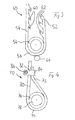
- Figure 1 shows of a rope end comprising a reel device
- figure 2 shows an alternative embodiment for the locking of the reel device comprising a ratchet mechanism
- figure 3 shows a further embodiment of a rope end with first and second fixing parts which can be connected at different positions
- figure 4 shows a further embodiment of a rope end where the rope end is fixed to a first rope part ahead of a sling via a clamp.
- FIG 1 shows an elevator rope 10 having a rope end 12 which is fixed on a reel body 14 of a reel device 16 which further comprises a reel frame 18.
- the reel body 14 is rotationally linked to the reel frame 18 via a pivot 20.
- the rope part wound on the reel body 14 forms a sling 22.
- the rope 10 comprises a first rope part 24 ahead of the sling 22.
- the reel body 14 comprises a number of perforations 26 along a circle around the pivot 20 which perforations can be protruded by a locking bolt 28 connected with the reel frame 18.
- the reel frame 18 is supported against rotation by the first rope part 24 ahead of the sling 22.
- the length of the rope can be easily adjusted to a desired length by fixing the rope end 12 to the reel body 14 and rotating the reel body according to a desired rope length. The exact rotational position is then locked by sticking the bolt 28 which is fixed in a perforation of the reel frame 18 through a perforation 26 of the reel body.
- the fixing of the rope end can be performed via a hole or recess perimeter of the reel body 14.
- the adjusting of the rope length is performed after the rope has been roped in the elevator shaft.
- This procedure is advantageous in that only elevator ropes have to be transported to the building site of the elevator, which are slightly longer than necessary, e. g. 20 centimeter to a meter longer than necessary.
- the elevator ropes are precut to said slightly larger length on the manufacturing site or a distribution stock of the elevator manufacturer or the rope manufacturer.
- the inventive easy adjustment of the rope length on the building site is quick and can be performed under constricted working conditions.
- Figure 2 shows another embodiment of a locking mechanism which could be provided in the reel device 18 of figure 1 .
- the reel body may have additionally or instead of the perforations 26 a wedged detent arrangement 30 on its circumference.
- a ratchet latch 32 is supported via a pivot 34 at the reel frame 18.
- the ratchet latch 32 is biased via a spring 36 against the ratchet detents 30.
- the spring 36 is counter supported by a stop 38 of the reel frame 18.
- the ratchet mechanism allows the winding of elevator rope on the reel body 14 but prevents the unwinding of the rope by the locking action of the ratchet latch gripping into the ratchet detents 30 via the spring force.
- the lock can be released by a release lever 40 which is accessible from outside of the reel frame 18.
- FIG. 3 shows a rope 50 having a rope end 52 which is bent around a first pulley 54 as to build a sling 56.
- a first rope part 58 ahead of the sling 56 comprises several, e.g. three spaced apart first fixing elements 60 in form of flaps comprising a perforation.
- the rope end 52 carries at least one second (e.g. three) fixing element 62 which is embodied e.g. also in a form of a flap comprising a perforation.
- the perforation of the flaps of the first and second fixing means 60, 62 can be brought in alignment in different positions as to adjust the rope end 52 to the first rope part 58 at appropriate selected different fixing positions. Accordingly, the rope length is adjusted.
- a counter pulley 64 can be provided outside of the sling which is pressed by a device (not shown) against the first pulley 54 as to press the sling 65 in between. Both pulleys 54, 64 are not rotatable so that also the pressure on the sling by the pulley 54 and the counter pulley 64 locks the rope length which is adjusted via corresponding connection of the first and second fixing means 60, 62.
- figure 4 shows a rope 70 having a rope end 72 which is bent to form a sling 74 which is guided around a first pulley 76 having an inner hole 78 for fixing the rope end.
- Ahead of the rope sling 74 is a first rope part 80.
- the adjustment of the length of the rope 70 is performed by bending the rope end 70 around the first pulley 76 and fixing the rope end 72 to the first rope part 80 via a clamp 82 in a desired position.
- the clamp 82 has a hinge 84 and the open end of the clamp 82 can be pressed together via a stud bolt 86.
- an easy length adjustment of the rope ends can be performed so that the precutting of the elevator ropes in a manufacturing or distribution site and transporting only already customized elevator ropes to the building side of the elevator can be realized.
- a counter pulley 64 (not shown) can be pressed against the pulley 76 to fix the length adjustment made by the clamp 82.
- first pulley and counter pulley 54, 64; 76, 64 can e.g. easily be realized by a beam having support for both pulleys and whereby the mutual distance of the pulleys can be adjusted, e. g. by a means of a long hole.
Landscapes
- Engineering & Computer Science (AREA)
- General Engineering & Computer Science (AREA)
- Mechanical Engineering (AREA)
- Lift-Guide Devices, And Elevator Ropes And Cables (AREA)
Priority Applications (3)
| Application Number | Priority Date | Filing Date | Title |
|---|---|---|---|
| EP20120197306 EP2743227A1 (de) | 2012-12-14 | 2012-12-14 | Aufzugsseil |
| CN201310757132.4A CN103867644B (zh) | 2012-12-14 | 2013-12-12 | 电梯绳索 |
| HK14111973.2A HK1198484B (en) | 2012-12-14 | 2014-11-27 | Elevator rope |
Applications Claiming Priority (1)
| Application Number | Priority Date | Filing Date | Title |
|---|---|---|---|
| EP20120197306 EP2743227A1 (de) | 2012-12-14 | 2012-12-14 | Aufzugsseil |
Publications (1)
| Publication Number | Publication Date |
|---|---|
| EP2743227A1 true EP2743227A1 (de) | 2014-06-18 |
Family
ID=47561127
Family Applications (1)
| Application Number | Title | Priority Date | Filing Date |
|---|---|---|---|
| EP20120197306 Withdrawn EP2743227A1 (de) | 2012-12-14 | 2012-12-14 | Aufzugsseil |
Country Status (2)
| Country | Link |
|---|---|
| EP (1) | EP2743227A1 (de) |
| CN (1) | CN103867644B (de) |
Cited By (4)
| Publication number | Priority date | Publication date | Assignee | Title |
|---|---|---|---|---|
| CN104210975A (zh) * | 2014-08-29 | 2014-12-17 | 苏州中州安勃起重有限公司 | 电动葫芦钢丝绳端部防松脱自锁绳套 |
| CN109386574A (zh) * | 2018-11-20 | 2019-02-26 | 深圳市菲特奥科技有限公司 | 一种绳带调节装置及具有该绳带调节装置的用品 |
| US11479407B2 (en) | 2018-01-09 | 2022-10-25 | Autostore Technology AS | Displacement mechanism for a remotely operated vehicle |
| US12180003B2 (en) | 2018-04-25 | 2024-12-31 | Autostore Technology AS | Container-handling vehicle |
Families Citing this family (1)
| Publication number | Priority date | Publication date | Assignee | Title |
|---|---|---|---|---|
| RU199077U1 (ru) * | 2020-03-17 | 2020-08-12 | Сергей Владимирович Свяслов | Коуш для канатных систем |
Citations (4)
| Publication number | Priority date | Publication date | Assignee | Title |
|---|---|---|---|---|
| GB191109715A (en) * | 1911-04-21 | 1912-01-18 | Otto Eigen | Improved Rope Loop Connection for Cages, Hoists, and the like. |
| US1436566A (en) * | 1922-02-01 | 1922-11-21 | R H Beaumont Company | Take-up for skip-hoist ropes |
| DE904456C (de) * | 1938-10-30 | 1954-02-18 | Elisabeth Heuer Geb Wortmann | Seilkauscheneinband fuer Foerderkoerbe |
| WO2007128859A1 (en) * | 2006-05-08 | 2007-11-15 | Kone Corporation | Method for installing the hoisting roping of an elevator |
Family Cites Families (4)
| Publication number | Priority date | Publication date | Assignee | Title |
|---|---|---|---|---|
| FI118534B (fi) * | 2006-05-08 | 2007-12-14 | Kone Corp | Menetelmä hissin nostoköysistön vaihtamiseksi ja vaihtamisessa käytettävä vetolaitejärjestely |
| FI20090310A7 (fi) * | 2009-08-28 | 2011-03-01 | Kone Corp | Menetelmä hissin köysittämiseksi, köysikela ja menetelmä nopeudenrajoittajan köyden tai korikaapelin asentamiseksi |
| FI122065B (fi) * | 2009-12-21 | 2011-08-15 | Kone Corp | Menetelmä hissiköysien vaihtamiseksi ja hissi |
| CN202082339U (zh) * | 2011-04-29 | 2011-12-21 | 中航光电科技股份有限公司 | 一种绳索固定结构 |
-
2012
- 2012-12-14 EP EP20120197306 patent/EP2743227A1/de not_active Withdrawn
-
2013
- 2013-12-12 CN CN201310757132.4A patent/CN103867644B/zh not_active Expired - Fee Related
Patent Citations (4)
| Publication number | Priority date | Publication date | Assignee | Title |
|---|---|---|---|---|
| GB191109715A (en) * | 1911-04-21 | 1912-01-18 | Otto Eigen | Improved Rope Loop Connection for Cages, Hoists, and the like. |
| US1436566A (en) * | 1922-02-01 | 1922-11-21 | R H Beaumont Company | Take-up for skip-hoist ropes |
| DE904456C (de) * | 1938-10-30 | 1954-02-18 | Elisabeth Heuer Geb Wortmann | Seilkauscheneinband fuer Foerderkoerbe |
| WO2007128859A1 (en) * | 2006-05-08 | 2007-11-15 | Kone Corporation | Method for installing the hoisting roping of an elevator |
Cited By (6)
| Publication number | Priority date | Publication date | Assignee | Title |
|---|---|---|---|---|
| CN104210975A (zh) * | 2014-08-29 | 2014-12-17 | 苏州中州安勃起重有限公司 | 电动葫芦钢丝绳端部防松脱自锁绳套 |
| CN104210975B (zh) * | 2014-08-29 | 2016-09-14 | 苏州中州安勃起重有限公司 | 电动葫芦钢丝绳端部防松脱自锁绳套 |
| US11479407B2 (en) | 2018-01-09 | 2022-10-25 | Autostore Technology AS | Displacement mechanism for a remotely operated vehicle |
| US11548731B2 (en) | 2018-01-09 | 2023-01-10 | Autostore Technology AS | Displacement mechanism for a remotely operated vehicle |
| US12180003B2 (en) | 2018-04-25 | 2024-12-31 | Autostore Technology AS | Container-handling vehicle |
| CN109386574A (zh) * | 2018-11-20 | 2019-02-26 | 深圳市菲特奥科技有限公司 | 一种绳带调节装置及具有该绳带调节装置的用品 |
Also Published As
| Publication number | Publication date |
|---|---|
| CN103867644B (zh) | 2017-08-08 |
| HK1198484A1 (en) | 2015-05-08 |
| CN103867644A (zh) | 2014-06-18 |
Similar Documents
| Publication | Publication Date | Title |
|---|---|---|
| EP2743227A1 (de) | Aufzugsseil | |
| US8544923B2 (en) | Lifting assembly | |
| KR101232227B1 (ko) | 안전네트 유닛 | |
| CN106185675A (zh) | 一种基站设备吊装辅助装置 | |
| EP3268246B1 (de) | Vorrichtung zur umreifung von transportgut | |
| JP5769498B2 (ja) | エレベータの改修方法および過速度非常止め装置 | |
| US7036761B2 (en) | Dual reel unwinder/rewinder with a slack take-up mechanism | |
| HK1198484B (en) | Elevator rope | |
| EP1532323B1 (de) | Befestigung f r bauelemente | |
| US20070018031A1 (en) | Wire cable dispenser | |
| US8292041B1 (en) | Friction brake | |
| KR101947515B1 (ko) | 추락방망 고정장치 | |
| CN214298744U (zh) | 过线滑轮机构及工程机械 | |
| JP2019092237A (ja) | 碍子連取付装置および碍子連取付方法 | |
| KR102642682B1 (ko) | 로프 꼬임 교정용 리와인딩 장치 및 그 장치를 이용한 드럼 로프 와인딩 방법 | |
| CN223102327U (zh) | 一种撕裂绳放置装置 | |
| JP6267903B2 (ja) | 樹木剪定等のための安全帯取付設備 | |
| US10953536B2 (en) | Support arrangement for supporting a load in an elevated position | |
| KR20230026059A (ko) | 철탑용 추락방지장치 | |
| EP1642856B1 (de) | Einrichtung und Verfahren zur Seilspannungsabgleichung | |
| US20180148964A1 (en) | Overhead door cable adjuster system and method | |
| KR101578282B1 (ko) | 카고 크레인의 붐대 긴장유지장치 | |
| JPH0549128A (ja) | 弛度制御架空地線張替工法 | |
| GB2444791A (en) | Tables equipped with electric cable spools | |
| KR200478093Y1 (ko) | 전력선의 이완도 조정 장치 |
Legal Events
| Date | Code | Title | Description |
|---|---|---|---|
| PUAI | Public reference made under article 153(3) epc to a published international application that has entered the european phase |
Free format text: ORIGINAL CODE: 0009012 |
|
| 17P | Request for examination filed |
Effective date: 20121214 |
|
| AK | Designated contracting states |
Kind code of ref document: A1 Designated state(s): AL AT BE BG CH CY CZ DE DK EE ES FI FR GB GR HR HU IE IS IT LI LT LU LV MC MK MT NL NO PL PT RO RS SE SI SK SM TR |
|
| AX | Request for extension of the european patent |
Extension state: BA ME |
|
| R17P | Request for examination filed (corrected) |
Effective date: 20141118 |
|
| RBV | Designated contracting states (corrected) |
Designated state(s): AL AT BE BG CH CY CZ DE DK EE ES FI FR GB GR HR HU IE IS IT LI LT LU LV MC MK MT NL NO PL PT RO RS SE SI SK SM TR |
|
| RIC1 | Information provided on ipc code assigned before grant |
Ipc: B66B 7/08 20060101ALI20150317BHEP Ipc: F16G 11/14 20060101ALI20150317BHEP Ipc: B66B 19/02 20060101AFI20150317BHEP |
|
| GRAP | Despatch of communication of intention to grant a patent |
Free format text: ORIGINAL CODE: EPIDOSNIGR1 |
|
| INTG | Intention to grant announced |
Effective date: 20150518 |
|
| STAA | Information on the status of an ep patent application or granted ep patent |
Free format text: STATUS: THE APPLICATION IS DEEMED TO BE WITHDRAWN |
|
| 18D | Application deemed to be withdrawn |
Effective date: 20150929 |