EP2743437A2 - Dispositif d'entraînement pour un battant d'une fenêtre ou d'une porte - Google Patents
Dispositif d'entraînement pour un battant d'une fenêtre ou d'une porte Download PDFInfo
- Publication number
- EP2743437A2 EP2743437A2 EP13196465.2A EP13196465A EP2743437A2 EP 2743437 A2 EP2743437 A2 EP 2743437A2 EP 13196465 A EP13196465 A EP 13196465A EP 2743437 A2 EP2743437 A2 EP 2743437A2
- Authority
- EP
- European Patent Office
- Prior art keywords
- lever
- chain
- drive device
- drive
- frame
- Prior art date
- Legal status (The legal status is an assumption and is not a legal conclusion. Google has not performed a legal analysis and makes no representation as to the accuracy of the status listed.)
- Granted
Links
Images


Classifications
-
- E—FIXED CONSTRUCTIONS
- E05—LOCKS; KEYS; WINDOW OR DOOR FITTINGS; SAFES
- E05F—DEVICES FOR MOVING WINGS INTO OPEN OR CLOSED POSITION; CHECKS FOR WINGS; WING FITTINGS NOT OTHERWISE PROVIDED FOR, CONCERNED WITH THE FUNCTIONING OF THE WING
- E05F11/00—Man-operated mechanisms for operating wings, including those which also operate the fastening
- E05F11/02—Man-operated mechanisms for operating wings, including those which also operate the fastening for wings in general, e.g. fanlights
- E05F11/04—Man-operated mechanisms for operating wings, including those which also operate the fastening for wings in general, e.g. fanlights with cords, chains or cables
- E05F11/06—Man-operated mechanisms for operating wings, including those which also operate the fastening for wings in general, e.g. fanlights with cords, chains or cables in guide-channels
-
- E—FIXED CONSTRUCTIONS
- E05—LOCKS; KEYS; WINDOW OR DOOR FITTINGS; SAFES
- E05F—DEVICES FOR MOVING WINGS INTO OPEN OR CLOSED POSITION; CHECKS FOR WINGS; WING FITTINGS NOT OTHERWISE PROVIDED FOR, CONCERNED WITH THE FUNCTIONING OF THE WING
- E05F15/00—Power-operated mechanisms for wings
- E05F15/60—Power-operated mechanisms for wings using electrical actuators
- E05F15/603—Power-operated mechanisms for wings using electrical actuators using rotary electromotors
- E05F15/611—Power-operated mechanisms for wings using electrical actuators using rotary electromotors for swinging wings
- E05F15/616—Power-operated mechanisms for wings using electrical actuators using rotary electromotors for swinging wings operated by push-pull mechanisms
- E05F15/619—Power-operated mechanisms for wings using electrical actuators using rotary electromotors for swinging wings operated by push-pull mechanisms using flexible or rigid rack-and-pinion arrangements
-
- E—FIXED CONSTRUCTIONS
- E05—LOCKS; KEYS; WINDOW OR DOOR FITTINGS; SAFES
- E05Y—INDEXING SCHEME ASSOCIATED WITH SUBCLASSES E05D AND E05F, RELATING TO CONSTRUCTION ELEMENTS, ELECTRIC CONTROL, POWER SUPPLY, POWER SIGNAL OR TRANSMISSION, USER INTERFACES, MOUNTING OR COUPLING, DETAILS, ACCESSORIES, AUXILIARY OPERATIONS NOT OTHERWISE PROVIDED FOR, APPLICATION THEREOF
- E05Y2201/00—Constructional elements; Accessories therefor
- E05Y2201/60—Suspension or transmission members; Accessories therefor
- E05Y2201/622—Suspension or transmission members elements
- E05Y2201/644—Flexible elongated pulling elements
- E05Y2201/656—Chains
-
- E—FIXED CONSTRUCTIONS
- E05—LOCKS; KEYS; WINDOW OR DOOR FITTINGS; SAFES
- E05Y—INDEXING SCHEME ASSOCIATED WITH SUBCLASSES E05D AND E05F, RELATING TO CONSTRUCTION ELEMENTS, ELECTRIC CONTROL, POWER SUPPLY, POWER SIGNAL OR TRANSMISSION, USER INTERFACES, MOUNTING OR COUPLING, DETAILS, ACCESSORIES, AUXILIARY OPERATIONS NOT OTHERWISE PROVIDED FOR, APPLICATION THEREOF
- E05Y2600/00—Mounting or coupling arrangements for elements provided for in this subclass
- E05Y2600/40—Mounting location; Visibility of the elements
- E05Y2600/41—Concealed
- E05Y2600/412—Concealed in the rabbet
-
- E—FIXED CONSTRUCTIONS
- E05—LOCKS; KEYS; WINDOW OR DOOR FITTINGS; SAFES
- E05Y—INDEXING SCHEME ASSOCIATED WITH SUBCLASSES E05D AND E05F, RELATING TO CONSTRUCTION ELEMENTS, ELECTRIC CONTROL, POWER SUPPLY, POWER SIGNAL OR TRANSMISSION, USER INTERFACES, MOUNTING OR COUPLING, DETAILS, ACCESSORIES, AUXILIARY OPERATIONS NOT OTHERWISE PROVIDED FOR, APPLICATION THEREOF
- E05Y2900/00—Application of doors, windows, wings or fittings thereof
- E05Y2900/50—Application of doors, windows, wings or fittings thereof for vehicles
- E05Y2900/53—Type of wing
- E05Y2900/55—Windows
Definitions
- the present invention relates to a drive device for a wing of a window or a door according to the preamble of claim 1.
- the DE 20 2008 004 021 discloses a drive device for a wing of a window or a door, in which via an electric motor drive of the wing can be moved to an open position.
- the chain is connected end to end with a rotatably mounted lever which is coupled via a first axis of rotation on the sash and a second axis of rotation with the chain.
- the chain is then connected on the opposite side with a drive which is rotatably mounted on the frame.
- the EP 1 118 740 discloses a drive for a rotatably mounted wing, wherein from a drive housing a movable chain is led out, which is connected at the end with a console or a lever.
- the console is mounted rotatably about a first axis on the wing and a second axis rotatably connected to the chain.
- the chain is designed as a rigid chain and the lever is rotatably mounted only about a single axis of rotation on the sash or the frame.
- the wing can be brought to the exact position on the drive means in an open position and held there.
- a "rigid" chain can be bent over a pinion of the drive at the individual Kettelgliedern, but the chain is so far rigid, that a buckling of the protruding from the drive section is not possible.
- the individual chain links are only slightly bendable in a direction perpendicular to the linear projecting portion, so that due to lack of degrees of freedom of the wing can be held in an exact position in an open position.
- both tensile forces and compressive forces between the frame and casement are transferable via the chain.
- the chain can both press the wing in the open position and intercept corresponding pressure forces of the wing in the closing direction even with wind loads to keep the wing in the open position, but also move the wing back to the closed position when needed.
- the rotatably mounted lever at the end of the chain extends substantially parallel to the chain.
- the lever can be designed step-shaped, so that over the lever lifting of an end portion of the chain away from the casement or the frame is possible, but a striking of the chain is avoided at an edge of the casement or the frame.
- the lever preferably has a receptacle on which the last link of the chain is fixed.
- the last chain link can be positively fixed to the receptacle, so that the lever and the chain form a unit that is rotatably mounted on the lever.
- the receptacle can be held on a web-shaped lever portion, on the end a rotation axis is provided. In the region of the web-shaped lever section, the chain and the lever section extend parallel and spaced, so that a compact construction of the lever mechanism is possible.
- the web-shaped lever section can have a length between 1 cm and 5 cm, in particular 2 to 4 cm.
- the lever can be made as a one-piece molding made of metal or plastic.
- the drive is fixed to the frame and the rotatable lever on the sash.
- the wing frame may be formed as a thermally insulated composite profile with an insulator profile, wherein the lever is rotatably mounted on an inner profile of the composite profile.
- the casement can be made with high thermal insulation, wherein the drive device does not adversely affect the thermal insulation of the composite profile.
- the lever may preferably be arranged completely in a receptacle of the inner profile, so that it is arranged with the wing closed on the "warm" side of the window, which is separated from the outer, colder side on the insulator profiles.
- the lever and at least the last link of the chain preferably form a unit which can only be moved together, ie only about which a rotation axis on the wing or frame is movable. As a result, a relative movement between the last link of the chain and the lever is avoided, so that unwanted relative movements are avoided even in the loaded state.
- a positive receptacle for the last link of the chain For a stable fixing can be formed on the lever a positive receptacle for the last link of the chain.
- FIG. 1 a drive device 1 is shown, in which a drive 3 is fixed to a frame 2.
- the drive 3 is not pivotally fixed to a groove of the frame 2.
- the box-shaped drive 3 has an electric motor, by means of which a chain 4 can be driven via at least one pinion, the chain 4 being designed as a rigid chain, which can be pivoted within a housing of the drive 3 about the individual axes of the chain links but which is formed from the drive 3 outstanding chain portion linear and rigid, wherein the chain 4 can be moved out of the housing of the drive 3 substantially in the horizontal direction.
- the chain 4 is fixed at the end to a rotatably mounted lever 5, which is fixed in this embodiment to a sash, not shown. It is of course also possible to provide the drive 3 on a casement and to mount the lever 5 rotatably on a frame 2.
- FIG. 2 is a section through the frame 2 and a sash 6 shown, between which the drive device is provided.
- the drive 3 In a closed position, the drive 3 is arranged in a rebate space between the window frame 2 and the sash frame 6 and completely surrounded by the frame 2 and the sash frame 6, so that it is not visible from the outside.
- the profile of the casement 6 is formed as a composite profile and comprises an inner profile 7, an insulator profile 8 made of plastic and an outer profile 9, wherein inner profile 7 and outer profile 9 are preferably made of metal, in particular aluminum.
- an L-shaped receptacle 10 is formed, in which the lever 5 is received with an end portion of the chain 4, wherein in the closed position in the L-shaped receptacle 10th also partially the drive 3 can be inserted.
- the composite profile further comprises a central seal 11 which is fixed to the réellenprofil 7 and further, a seal 12 is fixed to the outwardly facing portion of the inner profile 7, which serves to define a filling element, such as an insulating glass pane.
- a retaining strip 13 is attached for clamping the filling element.
- the components of the drive device with the drive 3, the chain 4 and the lever 5 are provided on the warm inner side and do not adversely affect the heat transfer.
- the middle seal 11 can come to rest on an inner profile of the frame 2, which can also be designed as a thermally insulated composite profile.
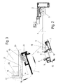
- FIG. 3 the area of the lever 5 of the drive device is shown in detail.
- a last chain link 16 of the chain 4 is fixed by a pin 15 on a receptacle 17 of the lever 5, wherein the chain link 16 is held positively and / or non-positively on the receptacle 17.
- the lever 5 has a web-shaped lever portion 18 which connects the receptacle 17 with a rotation axis 19 about which the lever 5 is pivotable.
- the web-shaped lever portion 18 extends substantially parallel to an end portion of the chain 4 and may have a length between 1 cm and 4 cm, so that at an opening of the wing, the end portion of the chain 4 can be lifted from the sash 6, as this in FIG. 3 is shown.
- the angle ⁇ between the web-shaped lever portion 18 and a horizontal wall in the closed position of the sash frame may be in a range between -2 ° and 75 ° and limited by a stop.
- the axis of rotation 19 of the lever 5 is held on a sliding block 20 which is fixed to a groove 21 of the inner profile 7.
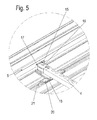
- FIG. 4 the drive device is shown in a plan view, in which the lever 5 and the sliding block 20 can be seen.
- the sliding block 20 is held in the groove and allows a rotational movement of the lever 5 about the rotation axis 19, wherein the lever 5 forms a solid unit with the chain 4, which can only be pivoted together.
- the rigid Chain 4 is rotatably mounted only about the axis 19 and has no further degrees of freedom in an open position, which would allow movement.
- the casement 6 can be held on the window frame 2 via a turn-tilt fitting or a pure tilt fitting or swivel fitting, wherein depending on the installation situation, the drive 3 can optionally be fastened to the top or the underside of the window frame 2.
- the kinematic system is statically determined and resilient.
Landscapes
- Power-Operated Mechanisms For Wings (AREA)
Applications Claiming Priority (1)
| Application Number | Priority Date | Filing Date | Title |
|---|---|---|---|
| DE202012104880.9U DE202012104880U1 (de) | 2012-12-14 | 2012-12-14 | Antriebseinrichtung für einen Flügel eines Fensters oder einer Tür |
Publications (3)
| Publication Number | Publication Date |
|---|---|
| EP2743437A2 true EP2743437A2 (fr) | 2014-06-18 |
| EP2743437A3 EP2743437A3 (fr) | 2017-10-11 |
| EP2743437B1 EP2743437B1 (fr) | 2020-04-22 |
Family
ID=49766916
Family Applications (1)
| Application Number | Title | Priority Date | Filing Date |
|---|---|---|---|
| EP13196465.2A Active EP2743437B1 (fr) | 2012-12-14 | 2013-12-10 | Dispositif d'entraînement pour un battant d'une fenêtre ou d'une porte |
Country Status (2)
| Country | Link |
|---|---|
| EP (1) | EP2743437B1 (fr) |
| DE (1) | DE202012104880U1 (fr) |
Families Citing this family (1)
| Publication number | Priority date | Publication date | Assignee | Title |
|---|---|---|---|---|
| CN107829645A (zh) * | 2017-11-15 | 2018-03-23 | 广西福美耀节能门窗有限公司 | 一种智能窗自动开合系统 |
Citations (2)
| Publication number | Priority date | Publication date | Assignee | Title |
|---|---|---|---|---|
| EP1118740A2 (fr) | 2000-01-21 | 2001-07-25 | GEZE GmbH | Entraíneur pour battant pivotant de fenêtre, porte ou similaire |
| DE202008004021U1 (de) | 2008-03-20 | 2008-05-21 | SCHÜCO International KG | Antriebseinrichtung für einen Flügel eines Fensters oder einer Tür |
Family Cites Families (3)
| Publication number | Priority date | Publication date | Assignee | Title |
|---|---|---|---|---|
| DE29817563U1 (de) * | 1998-10-01 | 1999-01-28 | D + H Mechatronic, Dingfelder + Kern GmbH, 22949 Ammersbek | Hubelement zum Betätigen von klappenartigen Elementen |
| WO2006089545A1 (fr) * | 2005-02-28 | 2006-08-31 | Vkr Holding A/S | Accouplement détachable |
| DE202010000269U1 (de) * | 2010-02-26 | 2011-08-23 | Stg-Beikirch Industrieelektronik + Sicherheitstechnik Gmbh & Co. Kg | Lagerbock und Ausstelleinrichtung |
-
2012
- 2012-12-14 DE DE202012104880.9U patent/DE202012104880U1/de not_active Expired - Lifetime
-
2013
- 2013-12-10 EP EP13196465.2A patent/EP2743437B1/fr active Active
Patent Citations (2)
| Publication number | Priority date | Publication date | Assignee | Title |
|---|---|---|---|---|
| EP1118740A2 (fr) | 2000-01-21 | 2001-07-25 | GEZE GmbH | Entraíneur pour battant pivotant de fenêtre, porte ou similaire |
| DE202008004021U1 (de) | 2008-03-20 | 2008-05-21 | SCHÜCO International KG | Antriebseinrichtung für einen Flügel eines Fensters oder einer Tür |
Also Published As
| Publication number | Publication date |
|---|---|
| DE202012104880U1 (de) | 2014-03-17 |
| EP2743437A3 (fr) | 2017-10-11 |
| EP2743437B1 (fr) | 2020-04-22 |
Similar Documents
| Publication | Publication Date | Title |
|---|---|---|
| EP3221540B1 (fr) | Dispositif d'étanchéité pour châssis mobile utilisé comme châssis coulissant ou châssis levant-coulissant mobile d'une fenêtre ou d'une porte | |
| DE19912717A1 (de) | Fenster oder Tür | |
| EP2780640B1 (fr) | Clapet d'aération | |
| DE202012001762U1 (de) | Kettenantrieb für einen Stellantrieb zum automatischen Öffnen und Schließen einer Lüftungsvorrichtung | |
| WO2019166264A1 (fr) | Dispositif pour recouvrir un ouvrant coulissant ou un ouvrant coulissant et levant pouvant être déplacé d'une fenêtre ou d'une porte | |
| EP2743437B1 (fr) | Dispositif d'entraînement pour un battant d'une fenêtre ou d'une porte | |
| DE202005000579U1 (de) | Profil für ein Fenster, eine Tür oder ein Fassadenelement mit elektrischem Kabel und Stecker für das Kabel | |
| DE202013008784U1 (de) | Beschlag eines zumindest hebbaren, vorzugsweise aber auch verschiebbaren Flügels von Fenstern oder Türen | |
| DE102013109293B3 (de) | Verschlusselement | |
| DE102011121359A1 (de) | Schiebeladenanordnung | |
| DE102014012029A1 (de) | Laufwagenanordnung für schwer heb- und bewegbare Flügel eines Fensters oder einer Tür | |
| DE102014101583A1 (de) | Türantriebsvorrichtung sowie damit versehene drehtür | |
| EP2103766B1 (fr) | Fenêtre ou porte comprenant un dispositif d'entraînement pour un battant de fenêtre ou de porte | |
| EP2699749B1 (fr) | Verrouillage de profilé de socle pour l'axe x et l'axe y d'un portail par sections ou d'un portail accordéon relevable par sections, équipé d'un dispositif d'arrêt de bord de fermeture et d'une porte d'issue de secours sans seuil à déclenchement libre | |
| DE10258694A1 (de) | Flügelprofil für Fenster und Türen mit Aufnahmekanal für Zusatzelemente | |
| WO2008145638A1 (fr) | Garniture de fenêtre comprenant un système d'entraînement à pignon et crémaillère pour déplacer un cadre de fenêtre dans un dormant | |
| AT513293B1 (de) | Tür oder Fenster, insbesondere Schiebetür oder Schiebefenster | |
| EP2105565B1 (fr) | Entraînement pour un battant d'une fenêtre | |
| EP4041974B1 (fr) | Dispositif d'ouverture destiné à un châssis oscillobasculant d'une fenêtre ou d'une porte | |
| DE19606006B4 (de) | Antrieb für einen Flügel eines Fensters, eine Klappe oder dergleichen | |
| DE102019000214B4 (de) | Licht- oder Belüftungskuppel für ein Gebäude, Verfahren zum Einbau einer Licht- oder Belüftungskuppel | |
| DE19937177A1 (de) | Torantriebsvorrichtung, insbesondere für Garagentore | |
| EP1582671B1 (fr) | Dispositif de monoeuvre pour battants de fenêtres ou de portes | |
| EP0889189B1 (fr) | Commande pour l'ouvrant d'une fenêtre, d'un volet ou similaire | |
| EP2700782B1 (fr) | Agencement de profilé |
Legal Events
| Date | Code | Title | Description |
|---|---|---|---|
| PUAI | Public reference made under article 153(3) epc to a published international application that has entered the european phase |
Free format text: ORIGINAL CODE: 0009012 |
|
| 17P | Request for examination filed |
Effective date: 20131210 |
|
| AK | Designated contracting states |
Kind code of ref document: A2 Designated state(s): AL AT BE BG CH CY CZ DE DK EE ES FI FR GB GR HR HU IE IS IT LI LT LU LV MC MK MT NL NO PL PT RO RS SE SI SK SM TR |
|
| AX | Request for extension of the european patent |
Extension state: BA ME |
|
| PUAL | Search report despatched |
Free format text: ORIGINAL CODE: 0009013 |
|
| AK | Designated contracting states |
Kind code of ref document: A3 Designated state(s): AL AT BE BG CH CY CZ DE DK EE ES FI FR GB GR HR HU IE IS IT LI LT LU LV MC MK MT NL NO PL PT RO RS SE SI SK SM TR |
|
| AX | Request for extension of the european patent |
Extension state: BA ME |
|
| RIC1 | Information provided on ipc code assigned before grant |
Ipc: E05F 15/12 00000000ALI20170901BHEP Ipc: E05F 11/06 20060101AFI20170901BHEP |
|
| STAA | Information on the status of an ep patent application or granted ep patent |
Free format text: STATUS: REQUEST FOR EXAMINATION WAS MADE |
|
| R17P | Request for examination filed (corrected) |
Effective date: 20180406 |
|
| RBV | Designated contracting states (corrected) |
Designated state(s): AL AT BE BG CH CY CZ DE DK EE ES FI FR GB GR HR HU IE IS IT LI LT LU LV MC MK MT NL NO PL PT RO RS SE SI SK SM TR |
|
| STAA | Information on the status of an ep patent application or granted ep patent |
Free format text: STATUS: EXAMINATION IS IN PROGRESS |
|
| 17Q | First examination report despatched |
Effective date: 20191007 |
|
| GRAP | Despatch of communication of intention to grant a patent |
Free format text: ORIGINAL CODE: EPIDOSNIGR1 |
|
| STAA | Information on the status of an ep patent application or granted ep patent |
Free format text: STATUS: GRANT OF PATENT IS INTENDED |
|
| INTG | Intention to grant announced |
Effective date: 20191122 |
|
| RIC1 | Information provided on ipc code assigned before grant |
Ipc: E05F 11/06 20060101AFI20191108BHEP Ipc: E05F 15/619 20150101ALI20191108BHEP |
|
| GRAS | Grant fee paid |
Free format text: ORIGINAL CODE: EPIDOSNIGR3 |
|
| GRAA | (expected) grant |
Free format text: ORIGINAL CODE: 0009210 |
|
| STAA | Information on the status of an ep patent application or granted ep patent |
Free format text: STATUS: THE PATENT HAS BEEN GRANTED |
|
| AK | Designated contracting states |
Kind code of ref document: B1 Designated state(s): AL AT BE BG CH CY CZ DE DK EE ES FI FR GB GR HR HU IE IS IT LI LT LU LV MC MK MT NL NO PL PT RO RS SE SI SK SM TR |
|
| REG | Reference to a national code |
Ref country code: GB Ref legal event code: FG4D Free format text: NOT ENGLISH |
|
| REG | Reference to a national code |
Ref country code: CH Ref legal event code: EP |
|
| REG | Reference to a national code |
Ref country code: DE Ref legal event code: R096 Ref document number: 502013014613 Country of ref document: DE |
|
| REG | Reference to a national code |
Ref country code: IE Ref legal event code: FG4D Free format text: LANGUAGE OF EP DOCUMENT: GERMAN |
|
| REG | Reference to a national code |
Ref country code: AT Ref legal event code: REF Ref document number: 1260274 Country of ref document: AT Kind code of ref document: T Effective date: 20200515 |
|
| REG | Reference to a national code |
Ref country code: NL Ref legal event code: FP |
|
| REG | Reference to a national code |
Ref country code: LT Ref legal event code: MG4D |
|
| PG25 | Lapsed in a contracting state [announced via postgrant information from national office to epo] |
Ref country code: NO Free format text: LAPSE BECAUSE OF FAILURE TO SUBMIT A TRANSLATION OF THE DESCRIPTION OR TO PAY THE FEE WITHIN THE PRESCRIBED TIME-LIMIT Effective date: 20200722 Ref country code: FI Free format text: LAPSE BECAUSE OF FAILURE TO SUBMIT A TRANSLATION OF THE DESCRIPTION OR TO PAY THE FEE WITHIN THE PRESCRIBED TIME-LIMIT Effective date: 20200422 Ref country code: IS Free format text: LAPSE BECAUSE OF FAILURE TO SUBMIT A TRANSLATION OF THE DESCRIPTION OR TO PAY THE FEE WITHIN THE PRESCRIBED TIME-LIMIT Effective date: 20200822 Ref country code: PT Free format text: LAPSE BECAUSE OF FAILURE TO SUBMIT A TRANSLATION OF THE DESCRIPTION OR TO PAY THE FEE WITHIN THE PRESCRIBED TIME-LIMIT Effective date: 20200824 Ref country code: SE Free format text: LAPSE BECAUSE OF FAILURE TO SUBMIT A TRANSLATION OF THE DESCRIPTION OR TO PAY THE FEE WITHIN THE PRESCRIBED TIME-LIMIT Effective date: 20200422 Ref country code: LT Free format text: LAPSE BECAUSE OF FAILURE TO SUBMIT A TRANSLATION OF THE DESCRIPTION OR TO PAY THE FEE WITHIN THE PRESCRIBED TIME-LIMIT Effective date: 20200422 Ref country code: GR Free format text: LAPSE BECAUSE OF FAILURE TO SUBMIT A TRANSLATION OF THE DESCRIPTION OR TO PAY THE FEE WITHIN THE PRESCRIBED TIME-LIMIT Effective date: 20200723 |
|
| PG25 | Lapsed in a contracting state [announced via postgrant information from national office to epo] |
Ref country code: BG Free format text: LAPSE BECAUSE OF FAILURE TO SUBMIT A TRANSLATION OF THE DESCRIPTION OR TO PAY THE FEE WITHIN THE PRESCRIBED TIME-LIMIT Effective date: 20200722 Ref country code: RS Free format text: LAPSE BECAUSE OF FAILURE TO SUBMIT A TRANSLATION OF THE DESCRIPTION OR TO PAY THE FEE WITHIN THE PRESCRIBED TIME-LIMIT Effective date: 20200422 Ref country code: LV Free format text: LAPSE BECAUSE OF FAILURE TO SUBMIT A TRANSLATION OF THE DESCRIPTION OR TO PAY THE FEE WITHIN THE PRESCRIBED TIME-LIMIT Effective date: 20200422 Ref country code: HR Free format text: LAPSE BECAUSE OF FAILURE TO SUBMIT A TRANSLATION OF THE DESCRIPTION OR TO PAY THE FEE WITHIN THE PRESCRIBED TIME-LIMIT Effective date: 20200422 |
|
| PG25 | Lapsed in a contracting state [announced via postgrant information from national office to epo] |
Ref country code: AL Free format text: LAPSE BECAUSE OF FAILURE TO SUBMIT A TRANSLATION OF THE DESCRIPTION OR TO PAY THE FEE WITHIN THE PRESCRIBED TIME-LIMIT Effective date: 20200422 |
|
| REG | Reference to a national code |
Ref country code: DE Ref legal event code: R097 Ref document number: 502013014613 Country of ref document: DE |
|
| PG25 | Lapsed in a contracting state [announced via postgrant information from national office to epo] |
Ref country code: ES Free format text: LAPSE BECAUSE OF FAILURE TO SUBMIT A TRANSLATION OF THE DESCRIPTION OR TO PAY THE FEE WITHIN THE PRESCRIBED TIME-LIMIT Effective date: 20200422 Ref country code: DK Free format text: LAPSE BECAUSE OF FAILURE TO SUBMIT A TRANSLATION OF THE DESCRIPTION OR TO PAY THE FEE WITHIN THE PRESCRIBED TIME-LIMIT Effective date: 20200422 Ref country code: EE Free format text: LAPSE BECAUSE OF FAILURE TO SUBMIT A TRANSLATION OF THE DESCRIPTION OR TO PAY THE FEE WITHIN THE PRESCRIBED TIME-LIMIT Effective date: 20200422 Ref country code: SM Free format text: LAPSE BECAUSE OF FAILURE TO SUBMIT A TRANSLATION OF THE DESCRIPTION OR TO PAY THE FEE WITHIN THE PRESCRIBED TIME-LIMIT Effective date: 20200422 Ref country code: RO Free format text: LAPSE BECAUSE OF FAILURE TO SUBMIT A TRANSLATION OF THE DESCRIPTION OR TO PAY THE FEE WITHIN THE PRESCRIBED TIME-LIMIT Effective date: 20200422 Ref country code: CZ Free format text: LAPSE BECAUSE OF FAILURE TO SUBMIT A TRANSLATION OF THE DESCRIPTION OR TO PAY THE FEE WITHIN THE PRESCRIBED TIME-LIMIT Effective date: 20200422 |
|
| PG25 | Lapsed in a contracting state [announced via postgrant information from national office to epo] |
Ref country code: PL Free format text: LAPSE BECAUSE OF FAILURE TO SUBMIT A TRANSLATION OF THE DESCRIPTION OR TO PAY THE FEE WITHIN THE PRESCRIBED TIME-LIMIT Effective date: 20200422 Ref country code: SK Free format text: LAPSE BECAUSE OF FAILURE TO SUBMIT A TRANSLATION OF THE DESCRIPTION OR TO PAY THE FEE WITHIN THE PRESCRIBED TIME-LIMIT Effective date: 20200422 |
|
| PLBE | No opposition filed within time limit |
Free format text: ORIGINAL CODE: 0009261 |
|
| STAA | Information on the status of an ep patent application or granted ep patent |
Free format text: STATUS: NO OPPOSITION FILED WITHIN TIME LIMIT |
|
| 26N | No opposition filed |
Effective date: 20210125 |
|
| PG25 | Lapsed in a contracting state [announced via postgrant information from national office to epo] |
Ref country code: SI Free format text: LAPSE BECAUSE OF FAILURE TO SUBMIT A TRANSLATION OF THE DESCRIPTION OR TO PAY THE FEE WITHIN THE PRESCRIBED TIME-LIMIT Effective date: 20200422 |
|
| REG | Reference to a national code |
Ref country code: CH Ref legal event code: PL |
|
| PG25 | Lapsed in a contracting state [announced via postgrant information from national office to epo] |
Ref country code: MC Free format text: LAPSE BECAUSE OF FAILURE TO SUBMIT A TRANSLATION OF THE DESCRIPTION OR TO PAY THE FEE WITHIN THE PRESCRIBED TIME-LIMIT Effective date: 20200422 |
|
| PG25 | Lapsed in a contracting state [announced via postgrant information from national office to epo] |
Ref country code: LU Free format text: LAPSE BECAUSE OF NON-PAYMENT OF DUE FEES Effective date: 20201210 Ref country code: IE Free format text: LAPSE BECAUSE OF NON-PAYMENT OF DUE FEES Effective date: 20201210 |
|
| PG25 | Lapsed in a contracting state [announced via postgrant information from national office to epo] |
Ref country code: LI Free format text: LAPSE BECAUSE OF NON-PAYMENT OF DUE FEES Effective date: 20201231 Ref country code: CH Free format text: LAPSE BECAUSE OF NON-PAYMENT OF DUE FEES Effective date: 20201231 |
|
| PG25 | Lapsed in a contracting state [announced via postgrant information from national office to epo] |
Ref country code: TR Free format text: LAPSE BECAUSE OF FAILURE TO SUBMIT A TRANSLATION OF THE DESCRIPTION OR TO PAY THE FEE WITHIN THE PRESCRIBED TIME-LIMIT Effective date: 20200422 Ref country code: MT Free format text: LAPSE BECAUSE OF FAILURE TO SUBMIT A TRANSLATION OF THE DESCRIPTION OR TO PAY THE FEE WITHIN THE PRESCRIBED TIME-LIMIT Effective date: 20200422 Ref country code: CY Free format text: LAPSE BECAUSE OF FAILURE TO SUBMIT A TRANSLATION OF THE DESCRIPTION OR TO PAY THE FEE WITHIN THE PRESCRIBED TIME-LIMIT Effective date: 20200422 |
|
| PG25 | Lapsed in a contracting state [announced via postgrant information from national office to epo] |
Ref country code: MK Free format text: LAPSE BECAUSE OF FAILURE TO SUBMIT A TRANSLATION OF THE DESCRIPTION OR TO PAY THE FEE WITHIN THE PRESCRIBED TIME-LIMIT Effective date: 20200422 |
|
| P01 | Opt-out of the competence of the unified patent court (upc) registered |
Effective date: 20230813 |
|
| PGFP | Annual fee paid to national office [announced via postgrant information from national office to epo] |
Ref country code: FR Payment date: 20231130 Year of fee payment: 11 Ref country code: AT Payment date: 20231204 Year of fee payment: 11 |
|
| PGFP | Annual fee paid to national office [announced via postgrant information from national office to epo] |
Ref country code: IT Payment date: 20231229 Year of fee payment: 11 |
|
| PGFP | Annual fee paid to national office [announced via postgrant information from national office to epo] |
Ref country code: NL Payment date: 20241115 Year of fee payment: 12 |
|
| REG | Reference to a national code |
Ref country code: AT Ref legal event code: MM01 Ref document number: 1260274 Country of ref document: AT Kind code of ref document: T Effective date: 20241210 |
|
| PG25 | Lapsed in a contracting state [announced via postgrant information from national office to epo] |
Ref country code: IT Free format text: LAPSE BECAUSE OF NON-PAYMENT OF DUE FEES Effective date: 20241210 |
|
| PG25 | Lapsed in a contracting state [announced via postgrant information from national office to epo] |
Ref country code: AT Free format text: LAPSE BECAUSE OF NON-PAYMENT OF DUE FEES Effective date: 20241210 Ref country code: FR Free format text: LAPSE BECAUSE OF NON-PAYMENT OF DUE FEES Effective date: 20241231 |
|
| PGFP | Annual fee paid to national office [announced via postgrant information from national office to epo] |
Ref country code: DE Payment date: 20251020 Year of fee payment: 13 |
|
| PGFP | Annual fee paid to national office [announced via postgrant information from national office to epo] |
Ref country code: GB Payment date: 20251203 Year of fee payment: 13 |
|
| PGFP | Annual fee paid to national office [announced via postgrant information from national office to epo] |
Ref country code: BE Payment date: 20251107 Year of fee payment: 13 |