EP2743593B1 - Haushaltsbackofen - Google Patents
Haushaltsbackofen Download PDFInfo
- Publication number
- EP2743593B1 EP2743593B1 EP13196639.2A EP13196639A EP2743593B1 EP 2743593 B1 EP2743593 B1 EP 2743593B1 EP 13196639 A EP13196639 A EP 13196639A EP 2743593 B1 EP2743593 B1 EP 2743593B1
- Authority
- EP
- European Patent Office
- Prior art keywords
- bulkhead
- air
- muffle
- oven according
- cooking oven
- Prior art date
- Legal status (The legal status is an assumption and is not a legal conclusion. Google has not performed a legal analysis and makes no representation as to the accuracy of the status listed.)
- Active
Links
- 238000010411 cooking Methods 0.000 title claims description 83
- 230000002093 peripheral effect Effects 0.000 claims description 16
- 238000010438 heat treatment Methods 0.000 claims description 8
- 235000013305 food Nutrition 0.000 description 11
- 230000000694 effects Effects 0.000 description 3
- 239000002184 metal Substances 0.000 description 3
- 238000004064 recycling Methods 0.000 description 3
- 238000000034 method Methods 0.000 description 2
- 208000027418 Wounds and injury Diseases 0.000 description 1
- 238000004873 anchoring Methods 0.000 description 1
- 238000007664 blowing Methods 0.000 description 1
- 230000000739 chaotic effect Effects 0.000 description 1
- 230000006835 compression Effects 0.000 description 1
- 238000007906 compression Methods 0.000 description 1
- 230000006378 damage Effects 0.000 description 1
- 239000012530 fluid Substances 0.000 description 1
- 208000014674 injury Diseases 0.000 description 1
- 238000009413 insulation Methods 0.000 description 1
- 238000010792 warming Methods 0.000 description 1
Images



Classifications
-
- F—MECHANICAL ENGINEERING; LIGHTING; HEATING; WEAPONS; BLASTING
- F24—HEATING; RANGES; VENTILATING
- F24C—DOMESTIC STOVES OR RANGES ; DETAILS OF DOMESTIC STOVES OR RANGES, OF GENERAL APPLICATION
- F24C15/00—Details
- F24C15/32—Arrangements of ducts for hot gases, e.g. in or around baking ovens
- F24C15/322—Arrangements of ducts for hot gases, e.g. in or around baking ovens with forced circulation
- F24C15/325—Arrangements of ducts for hot gases, e.g. in or around baking ovens with forced circulation electrically-heated
Definitions
- the present invention relates to cooking ovens and has been developed particularly with reference to convection cooking ovens.
- the domestic ovens for cooking foods typically comprise a bearing structure, which is associated to a muffle and a front door which closes the muffle frontally .
- a metal bulkhead formed by a metal sheet, facing to the rear wall of the muffle.
- This bulkhead divides the internal cavity of the muffle in a front cooking chamber, which extends between the door and the bulkhead, and a rear air distribution chamber, which extends between the bulkhead and the rear wall of the muffle.
- In the cooking chamber there is one or more shelves generally positioned at different heights, where food containers can be placed , to define different levels of cooking.
- the air distribution chamber is operatively arranged at least one heating resistance , which usually has a circular shape, as well as a fan, that is usually positioned in the area circumscribed by the resistance.
- the fan impeller is usually a centrifugal one and, the distribution chamber wherein it's located has an output section, for the airflow to the cooking chamber, as well as an input section.
- the output section usually includes a plurality of passageways, which are normally in peripheral positions with respect to the distribution chamber, generally outlined between the bulkhead and the rear or side wall of the muffle.
- the bulkhead has a smaller size compared to the size of the rear wall of the muffle and has a folded back edge, which is shaped in order to define the areas for the anchorage of the bulkhead to the rear wall of the muffle.
- the edge is cut, or otherwise shaped, also in order to outline the above mentioned peripheral airflow routes.
- the input airflow section of the distribution chamber is instead located in a central area of the bulkhead, configured substantially as a grid - usually by means of a multitude of holes close to each other -- located in front of the fan impeller. In this way the air is heated by the electric resistance and is pushed towards the air output devices of the distribution chamber, to flow substantially along the side walls of the muffle, toward the cooking chamber.
- the intermediate bulkhead of the muffle has essentially the task to direct the airflow inside the cavity of the muffle, using the grid that is normally dimensioned to ensure sufficient suction of "exhausted” air and prevent the risk of user injury.
- the cooking method resulting from this air distribution system depends mainly on the airflow of return - namely the sucked airflow in the central area of the bulkhead - that invests the foods placed in the oven at any level of shelves.
- the result is that the cooking is possible due to a quite chaotic movement of the airflow, which depends on the geometric shape of the grid of the bulkhead and on the direction of rotation of the fan impeller.
- Document DE 10 2008 042473 A1 discloses a cooking chamber unit for forming two cooking support regions and two gas outlet devices comprising two gas outlet units that open in to the support regions, respectively.
- EP 2735806 A1 discloses a household cooking oven provided with a bulkhead, wherein the frontal inlet comprises a plurality of circular openings distributed along the longitudinal direction.
- the main purpose of the present invention is essentially to provide a ventilated cooking oven in which the distribution of the air, in the cooking chamber, takes place with a controlled method, particularly in order to obtain a substantially symmetrical and/ or balanced distribution among the different levels of cooking.
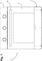
- number 1 indicates a household cooking oven according to the invention.
- the oven has a bearing structure or casing, shown with 2, in the front of which there is a control panel 3.
- a control panel 3 In the front of the casing 2 is also hinged, particularly in the lower edge, a door 4, provided with a handle 4a.
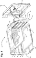
- the muffle 5 has a rigid metallic body, having two side walls, a bottom wall, a top wall and a rear wall; in figure 2 is represented the rear wall, denoted by 5a, while Figure 3 shows partially the lower wall 5b and the upper 5c, and one of the side walls 5d.
- the muffle 5 is preferably protected by a layer of insulation, already known and not represented.
- the muffle 5 defines a cavity, that can be frontally opened and closed by the door 4, in which is present a rear bulkhead 10, in a position generally facing the rear wall of the muffle 5a: in this way the bulkhead 10 divides the inside of the muffle 5 in a front cooking chamber that extends between the door 4 and the bulkhead 10, and a rear air-distribution chamber that extends between the bulkhead 10 and the rear wall of the muffle 5a.
- the supports consist in guides 6 shaped on the side walls of the muffle 5d, but in alternative embodiments, guides having a similar function can be represented by added grid , applied to the side walls 5d.
- guides 6 of the two opposite side walls 5d of the muffle are inserted in a sliding manner the edges of these shelves , one of these - here represented by an oven baking tray - is shown with number 7 in Figures 2 , 3 and 7 .
- this container 8a is represented a generic cooking vessel, in the example a baking pan, having a lateral size dimension smaller than the distance between the two side walls of the 5d muffle: this container 8a will be placed in a cooking shelf - schematically represented only in Figures 2 and 7 , where it is shown with 8 - having an appropriate size to engage its respective guides 6 of the lateral walls 5d.
- the guides 6 are defined at different heights, in order to arrange in the cooking chamber a plurality of different positions for different levels of cooking: as a simple example, this different cooking levels are shown in Figure 7 with the letters from "A" to "E ", from the bottom upwards .
- the cooking chamber is preferably but not necessarily equipped with suitable heating elements.
- two electric resistances or grill (broil) resistance - represented only in figure 3 , where one of them is indicated with 9.
- the resistance 9, usable particularly to cook food in the cooking chamber by intense radiant heat from the upper broil element, is placed within the muffle 5, on its upper wall 5b.
- the impeller 12 In the air distribution chamber defined between the rear wall of the muffle 5a and the bulkhead 10 are operatively arranged at least one electrical heating resistance 11 and the impeller 12 of a fan, particularly a centrifugal fan with axial suction and radial delivery.
- the fan motor marked with 13 in figure 2 , is assembled outside the muffle 5, behind its rear wall 5a, with its drive shaft passing through a slot in the rear wall.
- the impeller 12 rotates preferably within the region where the resistance 11 is placed, here defined as "rear", which has preferably a shape at least partially annular.
- the peripheral profile of the bulkhead 10 has perimeter size generally lower than that of the rear wall of the muffle 5a, as seen for example in Figures 2 , 3 and 7 .
- the assembly of the resistances 9 does not necessarily imply they pass through holes or breaks in the bulkhead 10.
- the different sizes between the perimeter wall 10 and rear wall 5a also allow, for example, to install a lamp directly on this last one - indicated with 14 only in Figure 3 - to light up inside when necessary the cooking chamber.
- the distribution chamber has an outlet section for the delivery of the air, through the fan impeller 12 , which forcibly inflates the air previously heated by the resistance 11 in the cooking chamber and an inlet section or recycling, through the impeller 12, which can draw air from the cooking chamber and then forces it back inside the same cooking chamber through the outlet section.
- This air is later again heated by the resistance 11.
- the outlet section comprises, similarly to the working principles of ventilated ovens, air passageways in generally peripheral positions of the air distribution chamber.
- the inlet section of the air distribution chamber of the oven 1 is not formed with a traditional grid of holes or similar shapes in the wall of the bulkhead 10.
- the inlet section comprises an air-suction cavity or chamber in the bulkhead 10.
- This air-suction cavity, 20 in Figures 2 and 3 has at least one inlet in the bulkhead 10 toward the cooking chamber and at least one outlet in the rear bulkhead facing towards the fan impeller 12 .
- the bulkhead 10 has a structure partially box-shaped to easier deliver the airflow in the internal cavity 20.
- the bulkhead 10 consists of at least two parts joined to get a cavity chamber, where the two parts in question can be welded, or stapled or otherwise made integral with each other (for example with screws or similar) .
- the bulkhead consists of two parts: the rear part 10a and the front one 10b, consisting of metal plates sheared and shaped, welded together.
- the rear part 10a defines at least one outlet 21, preferably in a central region that is generally flat.
- the periphery of the part 10a is instead preferably shaped in order to create areas for the complete anchorage of the bulkhead 10 to the rear wall 5a of the muffle.
- the peripheral part 10a that is generally preferably bent backwards, defines an upper zone 10a1 for anchoring, for example with screws, of the bulkhead 10 to the wall 5a, and a lower zone 10a2 for the support of the bulkhead 10 to the wall 5a. (of course, you can also fix the bulkhead 10 to the 5a wall in its lower parts).
- the peripheral profile of the part 10a is shaped, in its allocation 10a3, between the area 10a1 and the area 10a2, in order to create, together with the rear wall of the muffle 5a, passageway routes for delivery of the air outlet and then inlet from air-distribution chamber.
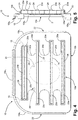
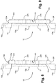
- the edge regions 10a3 are sliced in a way to lie along a vertical plane that is generally in parallel position far-between from a plane defined by the edges of the areas 10a1 and 10a2, as shown for example in Figure 5 ; in this way, when the bulkhead 10 is assembled inside the muffle 5, between the edge of the regions 10a3 and the front surface of the rear wall 5a are defined the above mentioned peripheral airflow passageways at least partially implementing the outlet section of the distribution chamber: these passageways are marked with 22 in the figures 3-6 .
- the front part 10b of the bulkhead 10 is shaped in order to define the cavity 20, together with the rear part 10a.
- the part 10b has a C shaped section.
- At least a cavity inlet 20 comprises a plurality of longitudinally extended inlet openings. These inlet openings are shown in images 4-6 with symbols from 23a to 23e but later, in other drawings, where not strictly needed from description, they will be all referred to as 23.
- the inlet openings 23 comprises a plurality of slits which extend substantially horizontally between two opposite lateral regions of the bulkhead 10 or the air-suction cavity 20, with such a slits that extend at different heights. Still with reference to the oven, one or more inlet openings 23 each have a mouth defined by a respective lip 24 projecting from the front 10b of the bulkhead 10 towards the cooking chamber. However, it has to be pointed out that the presence of the lips inlet 24 is merely optional and does not constitute an essential feature for the implementation of the invention. In the example shown, therefore, the openings 23 with its lips 24 are defined from the front 10b of the bulkhead 10.
- each inlet opening 23 extends in length between those two opposite lateral regions of the front of the bulkhead 10 or air-suction cavity 20, in a continuous way; in possible but not represented embodiment, however, one or more of the openings 23 can be interrupted and be constituted by a plurality of individual openings or slits horizontally aligned.
- the openings 23 may have same or may have different passage sections.
- the openings 23a-23c have substantially the same passage section, whereas, the openings 23d and 23e, have smaller passage section, being them shorter than the other.
- at least a pair of openings or slits are closer to each other with respect to other two slits in the plurality of ovens.
- the rear part 10a of the bulkhead 10 comprises at least one outlet opening 21 of the air-suction cavity or chamber 20.
- the outlet section of the cavity may consist in a grid of holes or only in a grid portion 10a.
- the preferred embodiment is provided with a single opening 21, preferably essentially coaxial to a rotation axis of the fan impeller 12 .
- the single opening 21 has essentially elliptical profile with a vertical major axis.
- a substantially elliptical opening 21 provides a larger passageway section than a circular one without affecting the performance of the impeller 12.
- the outlet 21 includes two areas (upper and lower respect to the axis of the impeller 12) where the inlet section is bigger, and two areas (the lateral areas respect to the axis of the impeller 12) which help the compression of the fluid: the combination of these geometries allows to obtain an outlet speed of the air from the impeller 12 in a more higher and homogeneous way compared to a circular opening.
- the back portion 10a of the bulkhead 10 has a projecting lip 21a oriented toward the impeller 12 of the fan, delimiting the at least one outlet 21.
- the lip 21a provides a continuity radius that allows to get closer the air suction section represented by the outlet 21 and the front face of the fan 12, improving its efficiency .
- the air suction cavity 20 has a peripheral profile with two opposite sides having an alternation of crest and valley (20a, 20b) at intermediate heights respect to the inlet openings 23.
- the opposite sides of the peripheral profile of the cavity 20 have alternating crests and valleys, some of which indicated with 20a and 20b, where the inlet opening 23 have opposite end regions each extending within the boundary of a respective crest. Said valleys allow to guide the air flow within the cavity 20 and meantime avoid the presence of dead volumes that could affect the intake air flow from the impeller 12.
- the bulkhead 10 includes some deflector elements which are part of the outlet section of the air distribution chamber, whose function is correcting the direction of air flow towards the zone of interest, specifically based on the inertia of motion generated by the impeller.
- the two deflectors 15 are provided in the back portion 10a of the bulkhead 10, in opposed zones of its upper portion.
- the two deflectors 15 have a not speculate positioning : in the example they have a curved profile, roughly arc of a circle, and are arranged one with the concavity facing upwards (the deflector 15 to the right of Figure 4 ) and the other one with the concavity facing downwards (the deflector 15 to the left of Figure 4 ), in order to address properly the supply air flow of the impeller 12.
- Deflector's positioning may vary in shape and number according to to the shape and direction of rotation of the impeller 12: the represented example refers to an impeller 12 rotating in a clockwise direction.
- the cooking chamber has at two opposite lateral walls 5d of the muffle 5, guides 6 to support removable shelves 7,8 in a plurality of different height positions, or cooking levels, schematically referred as A-E in figure 7 .
- the inlet openings 23 of the air-suction cavity 20 and the guides 6 being in such position that, in at least one of said height position A-E, a shelf 7,8 extends at an height that is intermediate to two said inlet openings 23.
- a shelf 7,8 extends at an height that is intermediate to two said inlet openings 23.
- the drip pan 7 occupies the position B, lying substantially opposite the lowest opening 23a of the bulkhead 10: this is substantially due to the fact that the drip pan 7 is higher than the shelf 9: it will be appreciated, however, that placing the shelf 8 in position B in place of the dripping pan 7, it will at an intermediate level between the openings 23a and 23b.
- FIG. 8 represents such a case, where the reference numbers are the same as in the previous figures, to identify elements technically equivalent to the ones described above.
- the inlet section of the air distribution chamber or cavity includes an additional opening 23f, whose shape may be similar to the openings 23a-23c, provided in correspondence of the lower side of the peripheral profile of cavity 20.
- positions A and B are commonly used for "multilevel” cooking, namely for 3 and 2 levels. Also, positions A and B can be used in case food and/or containers are bulky in the height dimension.
- Openings 23 could be substantially equidistant in height, as depicted for openings 23a-23d (not for 23d-23e), but, in alternative implementations, their mutual distance could be even different: generally speaking, the height and/or the mutual distance of openings 23 is determined by cooking levels (A-E) defined in the cooking chamber and by typology and number of convection cooking allowed to the oven 1 user.
- Figure 9 shows, as an example, a different position for openings 23 compared to figures 5 and 8 , where there is not opening 23a and the highest opening 23e is provided in correspondence to the upper side of the peripheral profile of cavity 20.
- the air flow forced by the impeller 12 is more controlled than in traditional solutions.
- the air-suction generated by the impeller in influenced by the presence of the cavity 20: in other words, air-suction isn't a directly from the cooking chamber, but through the cavity 20: the negative pressure that occurs within the cavity, by means of openings 23, generates the air recycling from the cooking chamber. Openings 23 allow the air recycling from well identified zones of the bulkhead 10, in order to create respective zones of controlled heating, with a substantially symmetrical and balanced distribution among the different cooking levels, as defined by tracks 6. In the traditional known architectures the air flow is not controlled, neither in blowing nor in suction.
- the air-suction cavity 20 creates a volume or storage unit from where the impeller 12 can suck without any impact onto the air flow within the cooking chamber.
- the cavity could even be extended beyond the air-suction zone of impeller 12; above all, the air-flow sucked by the cooking chamber into the distribution chamber is essentially determined by the shape of the bulkhead 10, namely by its openings 23, not by impeller 12.
- Openings 23 allow the air suction, by creating a kind of layers of hot air, which in turn transfer the heat to the food under cooking.
- Provided openings 23 are independent each other, they can assure a multi-level cooking: when 2 shelves are put inside the oven, actually resulting into a 2-levels cooking, each of them is supplied by at least two openings 23, with related air flows, below and above each shelf.
- openings 23 are even extended to the lower part of bulkhead 10, in order to generate a retrieving effect even below the cooking level B.
- the cavity 20 and the related lowest inlet opening for instance the 23f
- oven 1 could even be deprived of heating resistance below the lower wall 5b of muffle 5.
- openings 23 can have different passage sections , and then different air flow rate, allowing to differentiate cooking times over different levels A-E.
Landscapes
- Engineering & Computer Science (AREA)
- Chemical & Material Sciences (AREA)
- Combustion & Propulsion (AREA)
- Mechanical Engineering (AREA)
- General Engineering & Computer Science (AREA)
- Baking, Grill, Roasting (AREA)
- Electric Ovens (AREA)
Claims (13)
- Haushaltsbackofen (1), umfassend eine Lagerstruktur (2), eine Muffe (5) und eine Vordertür (4), um die Muffe (5) frontal zu schließen, wobei in der Muffe (5) ein Schott (10) vorliegt, das im Allgemeinen zu einer Muffenrückwand (5a) zeigt, das Schott (10) das Innere der Muffe (5) in eine Frontkochkammer, die sich zwischen der Türe (4) und dem Schott (10) erstreckt, und eine Rückluftverteilungskammer, die sich zwischen dem Schott (10) und der Muffenrückwand (5a) erstreckt, teilt, wobei in der Luftverteilungskammer betriebsfähig mindestens ein Heizwiderstand (11) und ein Laufrad (12) eines Zentrifugallüfters (12, 13) angeordnet sind, wobei die Luftverteilungskammer einen Auslassabschnitt (15, 22) zur Zufuhr von Luft zu der Kochkammer und einen Einlassabschnitt (20-23) zur Aufnahme von Luft von der Kochkammer aufweist, wobei der Auslassabschnitt (15, 22) Durchgänge (22) in im Allgemeinen peripheren Positionen der Luftverteilungskammer umfasst, wobei der Einlassabschnitt (20-23) einen Luftansaughohlraum oder eine -kammer (20) umfasst, der/die in dem Schott (10) definiert ist, wobei der Luftansaughohlraum (20) mindestens einen Einlass (23), der in einer Front (10b) des Schotts (10) definiert ist und zu der Kochkammer ausgerichtet ist, und mindestens einen Auslass (21), der in einer Rückseite (10a) des Schotts (10) definiert ist und zu dem Laufrad (12) des Lüfters (12, 13) ausgerichtet ist, aufweist, wobei der Ofen dadurch gekennzeichnet ist, dass der mindestens eine Auslass (21) ein im Wesentlichen elliptisches Profil mit im Wesentlichen vertikaler Hauptachse aufweist und wobei der mindestens eine Einlass (23) eine Vielzahl von sich längs erstreckenden Einlassöffnungen umfasst.
- Haushaltsbackofen nach Anspruch 1, wobei der mindestens eine Auslass eine einzelne Öffnung (21) umfasst, bevorzugt im Wesentlichen koaxial mit einer Drehachse des Laufrads (12) des Lüfters (12, 13).
- Haushaltsbackofen nach Anspruch 2, wobei die Einlassöffnungen eine Vielzahl von Schlitzen (23a-23e; 23a-23f; 23b-23f) umfassen, die sich im Wesentlichen horizontal zwischen zwei gegenüberliegenden seitlichen Bereichen des Schotts (10) erstrecken, wobei die Schlitze (23a-23e; 23a-23f; 23b-23f) der Vielzahl sich bei unterschiedlichen Höhen erstrecken.
- Haushaltsbackofen nach Anspruch 1, wobei das Schott (10) mindestens teilweise eine kastenähnliche Struktur aufweist.
- Haushaltsbackofen nach einem der vorstehenden Ansprüche, wobei das Schott (10) von mindestens zwei Teilen (10a, 10b) gebildet ist, die miteinander verbunden sind.
- Haushaltsbackofen nach Anspruch 4 oder 5, wobei das Schott aus einem Rückteil (10a) und einem Frontteil (10b) besteht, wobei das Frontteil (10b) C-förmig ist, um den Hohlraum (20) gemeinsam mit dem Rückteil (10a) zu definieren.
- Haushaltsbackofen nach Anspruch 1 oder Anspruch 2, wobei die Rückseite (10a) des Schotts (10) eine Fortsatzlippe (21a) zu dem Laufrad (12) des Lüfters (12, 13) aufweist und den mindestens einen Auslass (21) abgrenzt.
- Haushaltsbackofen nach Anspruch 1 oder Anspruch 3, wobei die Einlassöffnungen (23a-23e; 23a-23f; 23b-23f) jeweils einen Mund aufweisen, der durch eine jeweilige Lippe (24) definiert ist, die von der Front (10b) des Schotts (10) zu der Kochkammer vorsteht.
- Haushaltsbackofen nach Anspruch 1 oder Anspruch 3, wobei die Kochkammer bei zwei gegenüberliegenden Seitenwänden (5d) der Muffe (5) Stützmittel (6) aufweist, um entfernbare Roste (7, 8) in einer Vielzahl von unterschiedlichen Höhenpositionen (A-E) innerhalb der Kochkammer zu stützen, wobei die Einlassöffnungen (23a-23e; 23a-23f; 23b-23f) und die Stützmittel (6) in solchen Positionen sind, dass in mindestens einer der Höhenpositionen (A-E) ein Rost (7, 8) sich bei einer Höhe erstreckt, die zwischen zwei der Einlassöffnungen (23a-23e; 23a-23f; 23b-23f) ist.
- Haushaltsbackofen nach Anspruch 1 oder Anspruch 3, wobei der Luftansaughohlraum (20) ein Umfangsprofil mit zwei gegenüberliegenden Seiten aufweist, die eine Abwechslung von Erhebungen und Vertiefungen (20a, 20b) aufweisen, wobei eine oder mehrere der Einlassöffnungen (23a-23e; 23a-23f; 23b-23f) gegenüberliegende Endbereiche aufweisen, die sich jeweils innerhalb der Grenzen einer Erhöhung (20a) einer jeweiligen Seite des Umfangsprofils des Luftansaughohlraums (20) erstrecken.
- Haushaltsbackofen nach Anspruch 1 oder Anspruch 3, wobei die Vielzahl von Einlassöffnungen (23a-23e; 23a-23f; 23b-23f) mindestens ein Paar von Einlassöffnungen (23d, 23e; 23a-23f) umfasst, die näher zueinander sind als mindestens zwei andere Einlassöffnungen der Vielzahl (23a-23e; 23a-23f; 23b-23f), wobei das Paar von Einlassöffnungen bevorzugt in einem oberen Bereich der Front (10b) des Schotts (10) ist.
- Haushaltsbackofen nach Anspruch 1 oder Anspruch 3, wobei die Vielzahl von Einlassöffnungen (23a-23e; 23a-23f; 23b-23f) mindestens eine Einlassöffnung (23f; 23e) bei einem Umfangsprofil des Luftansaughohlraums (20) umfasst, insbesondere bei einer Oberseite oder einer Unterseite des Luftansaughohlraums (20).
- Haushaltsbackofen nach einem der vorstehenden Ansprüche, wobei der Auslassabschnitt (15, 22) ein oder mehrere Deflektorelemente (15) umfasst, um Luftrichtung zu korrigieren, insbesondere gemäß der Bewegungsträgheit, die durch das Laufrad (12) verursacht ist, wobei die Deflektorelemente (15) an der Rückseite (10b) des Schotts (10) sind.
Applications Claiming Priority (1)
| Application Number | Priority Date | Filing Date | Title |
|---|---|---|---|
| IT001075A ITTO20121075A1 (it) | 2012-12-14 | 2012-12-14 | Forno di cottura domestico |
Publications (2)
| Publication Number | Publication Date |
|---|---|
| EP2743593A1 EP2743593A1 (de) | 2014-06-18 |
| EP2743593B1 true EP2743593B1 (de) | 2020-03-18 |
Family
ID=47605684
Family Applications (1)
| Application Number | Title | Priority Date | Filing Date |
|---|---|---|---|
| EP13196639.2A Active EP2743593B1 (de) | 2012-12-14 | 2013-12-11 | Haushaltsbackofen |
Country Status (2)
| Country | Link |
|---|---|
| EP (1) | EP2743593B1 (de) |
| IT (1) | ITTO20121075A1 (de) |
Families Citing this family (1)
| Publication number | Priority date | Publication date | Assignee | Title |
|---|---|---|---|---|
| CN223095360U (zh) * | 2024-08-30 | 2025-07-15 | 宁波方太厨具有限公司 | 烘烤烹饪设备 |
Citations (1)
| Publication number | Priority date | Publication date | Assignee | Title |
|---|---|---|---|---|
| EP2735806A1 (de) * | 2012-11-21 | 2014-05-28 | Manitowoc Foodservice Companies, LLC | Garofen und Verfahren mit abnehmbarem Luftverteiler |
Family Cites Families (3)
| Publication number | Priority date | Publication date | Assignee | Title |
|---|---|---|---|---|
| GB631323A (en) * | 1946-09-04 | 1949-11-01 | Lyons & Co Ltd J | Improvements in and relating to ovens |
| DE102007030894A1 (de) * | 2007-07-03 | 2009-01-08 | BSH Bosch und Siemens Hausgeräte GmbH | Haushaltsgerät, insbesondere Gargerät |
| DE102008042473A1 (de) * | 2008-09-30 | 2010-04-01 | BSH Bosch und Siemens Hausgeräte GmbH | Haushaltsgargerätevorrichtung |
-
2012
- 2012-12-14 IT IT001075A patent/ITTO20121075A1/it unknown
-
2013
- 2013-12-11 EP EP13196639.2A patent/EP2743593B1/de active Active
Patent Citations (1)
| Publication number | Priority date | Publication date | Assignee | Title |
|---|---|---|---|---|
| EP2735806A1 (de) * | 2012-11-21 | 2014-05-28 | Manitowoc Foodservice Companies, LLC | Garofen und Verfahren mit abnehmbarem Luftverteiler |
Also Published As
| Publication number | Publication date |
|---|---|
| EP2743593A1 (de) | 2014-06-18 |
| ITTO20121075A1 (it) | 2014-06-15 |
Similar Documents
| Publication | Publication Date | Title |
|---|---|---|
| EP3003106B1 (de) | Luftfriteuse | |
| US10371391B2 (en) | Cooking oven provided for heat transfer by convection | |
| EP2467646B1 (de) | Ofen | |
| US11353220B2 (en) | Direct-heating fan oven | |
| EP1437552B1 (de) | Kochvorrichtung | |
| EP3365606B1 (de) | Konvektionsofen | |
| CN110916527A (zh) | 基于空气的炸锅 | |
| MXPA06011861A (es) | Control de aire para un horno de ladrillos. | |
| JP2005090952A (ja) | 対流式オーブンおよび関連するエア・フロー装置 | |
| CN102113836B (zh) | 利用贯流风扇的烹饪装置内热风对流系统 | |
| CN216293794U (zh) | 台面烹饪系统 | |
| CN202813465U (zh) | 加热烹调器 | |
| EP2743593B1 (de) | Haushaltsbackofen | |
| JP6382153B2 (ja) | 加熱調理器 | |
| KR100727875B1 (ko) | 오븐렌지 | |
| JP6593961B2 (ja) | 加熱調理器 | |
| EP1560464A1 (de) | Wandmontierter Mikrowellenofen | |
| GB1601690A (en) | Fan assisted grill oven | |
| JP3863539B2 (ja) | 加熱調理器 | |
| WO2015092642A1 (en) | Direct-heating fan oven | |
| JP2006003030A (ja) | 加熱調理器 | |
| KR100676135B1 (ko) | 이중 컨벡션팬이 구비된 가열조리기 | |
| CN217429810U (zh) | 一种烤制烹饪设备 | |
| WO2015092643A1 (en) | Direct-heating fan oven | |
| KR20090044741A (ko) | 오븐 |
Legal Events
| Date | Code | Title | Description |
|---|---|---|---|
| PUAI | Public reference made under article 153(3) epc to a published international application that has entered the european phase |
Free format text: ORIGINAL CODE: 0009012 |
|
| 17P | Request for examination filed |
Effective date: 20131211 |
|
| AK | Designated contracting states |
Kind code of ref document: A1 Designated state(s): AL AT BE BG CH CY CZ DE DK EE ES FI FR GB GR HR HU IE IS IT LI LT LU LV MC MK MT NL NO PL PT RO RS SE SI SK SM TR |
|
| AX | Request for extension of the european patent |
Extension state: BA ME |
|
| R17P | Request for examination filed (corrected) |
Effective date: 20141217 |
|
| RBV | Designated contracting states (corrected) |
Designated state(s): AL AT BE BG CH CY CZ DE DK EE ES FI FR GB GR HR HU IE IS IT LI LT LU LV MC MK MT NL NO PL PT RO RS SE SI SK SM TR |
|
| RAP1 | Party data changed (applicant data changed or rights of an application transferred) |
Owner name: WHIRLPOOL EMEA S.P.A |
|
| STAA | Information on the status of an ep patent application or granted ep patent |
Free format text: STATUS: EXAMINATION IS IN PROGRESS |
|
| 17Q | First examination report despatched |
Effective date: 20181211 |
|
| GRAP | Despatch of communication of intention to grant a patent |
Free format text: ORIGINAL CODE: EPIDOSNIGR1 |
|
| STAA | Information on the status of an ep patent application or granted ep patent |
Free format text: STATUS: GRANT OF PATENT IS INTENDED |
|
| INTG | Intention to grant announced |
Effective date: 20191211 |
|
| GRAS | Grant fee paid |
Free format text: ORIGINAL CODE: EPIDOSNIGR3 |
|
| GRAA | (expected) grant |
Free format text: ORIGINAL CODE: 0009210 |
|
| STAA | Information on the status of an ep patent application or granted ep patent |
Free format text: STATUS: THE PATENT HAS BEEN GRANTED |
|
| AK | Designated contracting states |
Kind code of ref document: B1 Designated state(s): AL AT BE BG CH CY CZ DE DK EE ES FI FR GB GR HR HU IE IS IT LI LT LU LV MC MK MT NL NO PL PT RO RS SE SI SK SM TR |
|
| REG | Reference to a national code |
Ref country code: GB Ref legal event code: FG4D |
|
| REG | Reference to a national code |
Ref country code: DE Ref legal event code: R096 Ref document number: 602013066908 Country of ref document: DE |
|
| REG | Reference to a national code |
Ref country code: AT Ref legal event code: REF Ref document number: 1246332 Country of ref document: AT Kind code of ref document: T Effective date: 20200415 Ref country code: IE Ref legal event code: FG4D |
|
| PG25 | Lapsed in a contracting state [announced via postgrant information from national office to epo] |
Ref country code: NO Free format text: LAPSE BECAUSE OF FAILURE TO SUBMIT A TRANSLATION OF THE DESCRIPTION OR TO PAY THE FEE WITHIN THE PRESCRIBED TIME-LIMIT Effective date: 20200618 Ref country code: FI Free format text: LAPSE BECAUSE OF FAILURE TO SUBMIT A TRANSLATION OF THE DESCRIPTION OR TO PAY THE FEE WITHIN THE PRESCRIBED TIME-LIMIT Effective date: 20200318 Ref country code: RS Free format text: LAPSE BECAUSE OF FAILURE TO SUBMIT A TRANSLATION OF THE DESCRIPTION OR TO PAY THE FEE WITHIN THE PRESCRIBED TIME-LIMIT Effective date: 20200318 |
|
| REG | Reference to a national code |
Ref country code: NL Ref legal event code: MP Effective date: 20200318 |
|
| PG25 | Lapsed in a contracting state [announced via postgrant information from national office to epo] |
Ref country code: SE Free format text: LAPSE BECAUSE OF FAILURE TO SUBMIT A TRANSLATION OF THE DESCRIPTION OR TO PAY THE FEE WITHIN THE PRESCRIBED TIME-LIMIT Effective date: 20200318 Ref country code: LV Free format text: LAPSE BECAUSE OF FAILURE TO SUBMIT A TRANSLATION OF THE DESCRIPTION OR TO PAY THE FEE WITHIN THE PRESCRIBED TIME-LIMIT Effective date: 20200318 Ref country code: GR Free format text: LAPSE BECAUSE OF FAILURE TO SUBMIT A TRANSLATION OF THE DESCRIPTION OR TO PAY THE FEE WITHIN THE PRESCRIBED TIME-LIMIT Effective date: 20200619 Ref country code: BG Free format text: LAPSE BECAUSE OF FAILURE TO SUBMIT A TRANSLATION OF THE DESCRIPTION OR TO PAY THE FEE WITHIN THE PRESCRIBED TIME-LIMIT Effective date: 20200618 Ref country code: HR Free format text: LAPSE BECAUSE OF FAILURE TO SUBMIT A TRANSLATION OF THE DESCRIPTION OR TO PAY THE FEE WITHIN THE PRESCRIBED TIME-LIMIT Effective date: 20200318 |
|
| REG | Reference to a national code |
Ref country code: LT Ref legal event code: MG4D |
|
| PG25 | Lapsed in a contracting state [announced via postgrant information from national office to epo] |
Ref country code: NL Free format text: LAPSE BECAUSE OF FAILURE TO SUBMIT A TRANSLATION OF THE DESCRIPTION OR TO PAY THE FEE WITHIN THE PRESCRIBED TIME-LIMIT Effective date: 20200318 |
|
| PG25 | Lapsed in a contracting state [announced via postgrant information from national office to epo] |
Ref country code: LT Free format text: LAPSE BECAUSE OF FAILURE TO SUBMIT A TRANSLATION OF THE DESCRIPTION OR TO PAY THE FEE WITHIN THE PRESCRIBED TIME-LIMIT Effective date: 20200318 Ref country code: PT Free format text: LAPSE BECAUSE OF FAILURE TO SUBMIT A TRANSLATION OF THE DESCRIPTION OR TO PAY THE FEE WITHIN THE PRESCRIBED TIME-LIMIT Effective date: 20200812 Ref country code: SM Free format text: LAPSE BECAUSE OF FAILURE TO SUBMIT A TRANSLATION OF THE DESCRIPTION OR TO PAY THE FEE WITHIN THE PRESCRIBED TIME-LIMIT Effective date: 20200318 Ref country code: EE Free format text: LAPSE BECAUSE OF FAILURE TO SUBMIT A TRANSLATION OF THE DESCRIPTION OR TO PAY THE FEE WITHIN THE PRESCRIBED TIME-LIMIT Effective date: 20200318 Ref country code: CZ Free format text: LAPSE BECAUSE OF FAILURE TO SUBMIT A TRANSLATION OF THE DESCRIPTION OR TO PAY THE FEE WITHIN THE PRESCRIBED TIME-LIMIT Effective date: 20200318 Ref country code: RO Free format text: LAPSE BECAUSE OF FAILURE TO SUBMIT A TRANSLATION OF THE DESCRIPTION OR TO PAY THE FEE WITHIN THE PRESCRIBED TIME-LIMIT Effective date: 20200318 Ref country code: SK Free format text: LAPSE BECAUSE OF FAILURE TO SUBMIT A TRANSLATION OF THE DESCRIPTION OR TO PAY THE FEE WITHIN THE PRESCRIBED TIME-LIMIT Effective date: 20200318 Ref country code: IS Free format text: LAPSE BECAUSE OF FAILURE TO SUBMIT A TRANSLATION OF THE DESCRIPTION OR TO PAY THE FEE WITHIN THE PRESCRIBED TIME-LIMIT Effective date: 20200718 |
|
| REG | Reference to a national code |
Ref country code: AT Ref legal event code: MK05 Ref document number: 1246332 Country of ref document: AT Kind code of ref document: T Effective date: 20200318 |
|
| REG | Reference to a national code |
Ref country code: DE Ref legal event code: R097 Ref document number: 602013066908 Country of ref document: DE |
|
| PLBE | No opposition filed within time limit |
Free format text: ORIGINAL CODE: 0009261 |
|
| STAA | Information on the status of an ep patent application or granted ep patent |
Free format text: STATUS: NO OPPOSITION FILED WITHIN TIME LIMIT |
|
| PG25 | Lapsed in a contracting state [announced via postgrant information from national office to epo] |
Ref country code: ES Free format text: LAPSE BECAUSE OF FAILURE TO SUBMIT A TRANSLATION OF THE DESCRIPTION OR TO PAY THE FEE WITHIN THE PRESCRIBED TIME-LIMIT Effective date: 20200318 Ref country code: DK Free format text: LAPSE BECAUSE OF FAILURE TO SUBMIT A TRANSLATION OF THE DESCRIPTION OR TO PAY THE FEE WITHIN THE PRESCRIBED TIME-LIMIT Effective date: 20200318 Ref country code: AT Free format text: LAPSE BECAUSE OF FAILURE TO SUBMIT A TRANSLATION OF THE DESCRIPTION OR TO PAY THE FEE WITHIN THE PRESCRIBED TIME-LIMIT Effective date: 20200318 |
|
| PGFP | Annual fee paid to national office [announced via postgrant information from national office to epo] |
Ref country code: FR Payment date: 20201112 Year of fee payment: 8 Ref country code: IT Payment date: 20201110 Year of fee payment: 8 Ref country code: DE Payment date: 20201201 Year of fee payment: 8 Ref country code: GB Payment date: 20201202 Year of fee payment: 8 |
|
| 26N | No opposition filed |
Effective date: 20201221 |
|
| PG25 | Lapsed in a contracting state [announced via postgrant information from national office to epo] |
Ref country code: PL Free format text: LAPSE BECAUSE OF FAILURE TO SUBMIT A TRANSLATION OF THE DESCRIPTION OR TO PAY THE FEE WITHIN THE PRESCRIBED TIME-LIMIT Effective date: 20200318 |
|
| PG25 | Lapsed in a contracting state [announced via postgrant information from national office to epo] |
Ref country code: SI Free format text: LAPSE BECAUSE OF FAILURE TO SUBMIT A TRANSLATION OF THE DESCRIPTION OR TO PAY THE FEE WITHIN THE PRESCRIBED TIME-LIMIT Effective date: 20200318 |
|
| REG | Reference to a national code |
Ref country code: CH Ref legal event code: PL |
|
| PG25 | Lapsed in a contracting state [announced via postgrant information from national office to epo] |
Ref country code: MC Free format text: LAPSE BECAUSE OF FAILURE TO SUBMIT A TRANSLATION OF THE DESCRIPTION OR TO PAY THE FEE WITHIN THE PRESCRIBED TIME-LIMIT Effective date: 20200318 |
|
| REG | Reference to a national code |
Ref country code: BE Ref legal event code: MM Effective date: 20201231 |
|
| PG25 | Lapsed in a contracting state [announced via postgrant information from national office to epo] |
Ref country code: IE Free format text: LAPSE BECAUSE OF NON-PAYMENT OF DUE FEES Effective date: 20201211 Ref country code: LU Free format text: LAPSE BECAUSE OF NON-PAYMENT OF DUE FEES Effective date: 20201211 |
|
| PG25 | Lapsed in a contracting state [announced via postgrant information from national office to epo] |
Ref country code: LI Free format text: LAPSE BECAUSE OF NON-PAYMENT OF DUE FEES Effective date: 20201231 Ref country code: CH Free format text: LAPSE BECAUSE OF NON-PAYMENT OF DUE FEES Effective date: 20201231 |
|
| PG25 | Lapsed in a contracting state [announced via postgrant information from national office to epo] |
Ref country code: TR Free format text: LAPSE BECAUSE OF FAILURE TO SUBMIT A TRANSLATION OF THE DESCRIPTION OR TO PAY THE FEE WITHIN THE PRESCRIBED TIME-LIMIT Effective date: 20200318 Ref country code: MT Free format text: LAPSE BECAUSE OF FAILURE TO SUBMIT A TRANSLATION OF THE DESCRIPTION OR TO PAY THE FEE WITHIN THE PRESCRIBED TIME-LIMIT Effective date: 20200318 Ref country code: CY Free format text: LAPSE BECAUSE OF FAILURE TO SUBMIT A TRANSLATION OF THE DESCRIPTION OR TO PAY THE FEE WITHIN THE PRESCRIBED TIME-LIMIT Effective date: 20200318 |
|
| PG25 | Lapsed in a contracting state [announced via postgrant information from national office to epo] |
Ref country code: MK Free format text: LAPSE BECAUSE OF FAILURE TO SUBMIT A TRANSLATION OF THE DESCRIPTION OR TO PAY THE FEE WITHIN THE PRESCRIBED TIME-LIMIT Effective date: 20200318 Ref country code: AL Free format text: LAPSE BECAUSE OF FAILURE TO SUBMIT A TRANSLATION OF THE DESCRIPTION OR TO PAY THE FEE WITHIN THE PRESCRIBED TIME-LIMIT Effective date: 20200318 |
|
| REG | Reference to a national code |
Ref country code: DE Ref legal event code: R119 Ref document number: 602013066908 Country of ref document: DE |
|
| PG25 | Lapsed in a contracting state [announced via postgrant information from national office to epo] |
Ref country code: BE Free format text: LAPSE BECAUSE OF NON-PAYMENT OF DUE FEES Effective date: 20201231 |
|
| GBPC | Gb: european patent ceased through non-payment of renewal fee |
Effective date: 20211211 |
|
| PG25 | Lapsed in a contracting state [announced via postgrant information from national office to epo] |
Ref country code: GB Free format text: LAPSE BECAUSE OF NON-PAYMENT OF DUE FEES Effective date: 20211211 Ref country code: DE Free format text: LAPSE BECAUSE OF NON-PAYMENT OF DUE FEES Effective date: 20220701 |
|
| PG25 | Lapsed in a contracting state [announced via postgrant information from national office to epo] |
Ref country code: FR Free format text: LAPSE BECAUSE OF NON-PAYMENT OF DUE FEES Effective date: 20211231 |
|
| PG25 | Lapsed in a contracting state [announced via postgrant information from national office to epo] |
Ref country code: IT Free format text: LAPSE BECAUSE OF NON-PAYMENT OF DUE FEES Effective date: 20211211 |