EP2743631A2 - Dispositif de montage d'une lunette de visée avec inclinaison prédéfini ajustable - Google Patents
Dispositif de montage d'une lunette de visée avec inclinaison prédéfini ajustable Download PDFInfo
- Publication number
- EP2743631A2 EP2743631A2 EP13005372.1A EP13005372A EP2743631A2 EP 2743631 A2 EP2743631 A2 EP 2743631A2 EP 13005372 A EP13005372 A EP 13005372A EP 2743631 A2 EP2743631 A2 EP 2743631A2
- Authority
- EP
- European Patent Office
- Prior art keywords
- scope mount
- attachment
- front inclination
- adjustable front
- base body
- Prior art date
- Legal status (The legal status is an assumption and is not a legal conclusion. Google has not performed a legal analysis and makes no representation as to the accuracy of the status listed.)
- Granted
Links
Images


Classifications
-
- F—MECHANICAL ENGINEERING; LIGHTING; HEATING; WEAPONS; BLASTING
- F41—WEAPONS
- F41G—WEAPON SIGHTS; AIMING
- F41G1/00—Sighting devices
- F41G1/38—Telescopic sights specially adapted for smallarms or ordnance; Supports or mountings therefor
- F41G1/387—Mounting telescopic sights on smallarms
-
- F—MECHANICAL ENGINEERING; LIGHTING; HEATING; WEAPONS; BLASTING
- F41—WEAPONS
- F41G—WEAPON SIGHTS; AIMING
- F41G11/00—Details of sighting or aiming apparatus; Accessories
- F41G11/001—Means for mounting tubular or beam shaped sighting or aiming devices on firearms
- F41G11/003—Mountings with a dove tail element, e.g. "Picatinny rail systems"
-
- F—MECHANICAL ENGINEERING; LIGHTING; HEATING; WEAPONS; BLASTING
- F41—WEAPONS
- F41G—WEAPON SIGHTS; AIMING
- F41G11/00—Details of sighting or aiming apparatus; Accessories
- F41G11/001—Means for mounting tubular or beam shaped sighting or aiming devices on firearms
- F41G11/005—Mountings using a pivot point and an anchoring point
- F41G11/007—Mountings using a pivot point and an anchoring point the device being tilted in a vertical plane
Definitions
- the invention relates to a scope mount with adjustable pre-tilt to change the pre-tilt angle between scope and barrel when shooting at long distances so that the vertical displacement of the scope is sufficient to adjust it to the desired shooting distance can.
- the projectile After firing from a firearm, the projectile follows a trajectory, the curvature of which depends on various influencing factors, such as projectile weight and projectile velocity.
- the telescopic sight can be adjusted to different shooting distances by adjusting the reticle.
- the adjustment path of each riflescope is mechanically limited, so that, for example, only a distance range of about 50 - 600 m can be covered. If the desired shooting distance is outside this range, for example at 800 m, this can no longer be achieved by adjusting the reticle.
- Riflescopes are connected to the firearm using riflescope mountings. Normally, the optical axis of the telescopic sight and the barrel axis of the weapon are coaxial with each other. Due to the greatly decreasing at long distances to the target trajectory of the projectile in such cases, the riflescope is mounted with a vorgeneigten scope mount on the weapon. In this case, different pretilt angles are necessary for different combinations of ammunition, barrel, weapon system, scope mount, telescopic sight and desired shot distance, so that the available vertical displacement of the scope is sufficient to set the reticle to different firing ranges.
- the riflescope is mounted with a riflescope assembly which has a fixed pretilt of, for example, 20 MOA ( M inute O f A ngle, angular minutes), this combination may suit a particular application. However, another combination may require a different pretilt angle be able to set the sight of the riflescope to the desired shooting distance can.
- a riflescope assembly which has a fixed pretilt of, for example, 20 MOA ( M inute O f A ngle, angular minutes)
- this combination may suit a particular application.
- another combination may require a different pretilt angle be able to set the sight of the riflescope to the desired shooting distance can.
- a rifle scope mount with adjustable forward tilt can be used in hunting or sport shooting.
- military-used weapons with a particularly long range and correspondingly powerful calibers such an assembly brings decisive advantages for the user.
- the shaft or the screw in at least one of the two parts must have a slight radial play.
- this game is very small in precisely worked hinge joints, but can lead to precision losses during use, when the forces are large enough and the shaft is radially displaced within the bore in the context of this game.
- the axial clamping together of the hinge by means of a screw is due to the necessary play the shaft in one of the components ultimately a frictional and no positive connection.
- Absolute reliability and ruggedness in the harshest of conditions is crucial, especially for military-grade weapons.
- the scope mount from as few as possible Parts exist and the connection of the individual components should be positive and not frictionally.
- as little as possible parts to be lost should be installed, which means that the scope mount for adjusting the tilt should not be disassembled or removed from the weapon if possible.
- Of particular importance is the simplest possible handling of the adjustment so that operator error can be largely excluded.
- the object of the invention is to overcome the described disadvantage of the prior art.
- a riflescope mounting with adjustable tilt which is characterized in that a base body and an attachment by the arrangement of a clamping screw at an angle greater than the self-locking material pairing and less than 90 ° have a positive connection.
- the object of the invention is further achieved by telescopic sight mounting with adjustable pre-tilt, which is characterized in that the base body and the attachment have a conical connection.
- the scope mount according to the invention meets the requirements mentioned in an excellent manner.
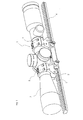
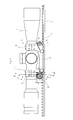
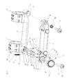
- Fig. 1 and 2 show a riflescope mounting 1, the main body 2 by way of example with a in the utility model DE 20 2009 017 398.4 explained clamping system is provided, wherein the base body is fixed by means of the clamping system on a Picatinny rail 4.
- the Picatinny rail is in turn mounted on the gun case (not shown in the figures).
- the attachment 3 clamps together with the front half-shell 5 and the rear half-shell 6, the riflescope 7.
- the top of the article 3 may be provided with a further Picatinny rail, on which the target device is mounted.
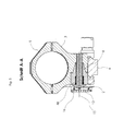
- the main body 2 has a taper 8 with a bore 9 (see Fig. 3 ).
- the attachment 3 has a countersink 10 (see Fig. 4 ) and an internal thread 11 (see Fig. 3 ) on.
- the first clamping screw 12 thus connects the main body 2 backlash with the attachment 3.
- the main body 2 forms with the attachment 3 a hinge about the hinge axis 13.
- a compound with a cylindrical hinge pin guaranteed absolute freedom of play in a conical connection, which is a great advantage.
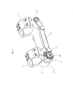
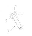
- the main body 2 has an extension 14 and this in turn a circular pin 15 on which the thumbwheel 16 is rotatably mounted (see Fig. 6 ).
- a circular pin 15 on which the thumbwheel 16 is rotatably mounted (see Fig. 6 ).
- the threaded pin 17 is secured with locking lacquer in the internal thread 19 against rotation (see Fig. 8 ).
- the thumbwheel 16 has on its circumference, for example, eight flat surfaces with associated labels.
- the surface 20 is picked out by way of example, to which the lettering "20" is assigned. Each surface is assigned a certain angle of the pre-tilt.
- the necessary distance "A" in Fig. 8 the surfaces to the axis of rotation of the adjusting wheel 16 can be calculated via angle functions. In the exemplary embodiment shown, there are eight possible angular positions from 0 to 70 MOA in ten MOA increments. Other numbers of areas with different pitches are possible.
- the lateral surface of the adjusting wheel 16 may have a slope in the form of a spiral (not shown in the figures) to allow a continuous adjustment of the inclination angle. For tool-free handling the adjusting wheel 16 is provided with a corrugation 21.
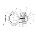
- a slot 22 extends through the circular pin 15 and the extension 14. This slot 22 has an angle ß to the contact surface 23 on the attachment 3 (see Fig. 4 and 9 ).
- the slot 22 is from a second clamping screw 24 (see Fig. 10 ), which rests in the clamped state with the base 25 of the head 26 on the surface 27 of the circular pin 15.
- the surface 27 is at right angles to the slot 22.
- the threaded shaft 28 of the second clamping screw 24 engages in the internal thread 29 in the attachment 3.
- the internal thread 29 has the same angle ß to the contact surface 23 as the slot 22 (see Fig. 4 . 7 and 9 ).
- the extension 14 and the circular pin 15 have a first bore 33 and a second bore 34. In these bores sits a first clamping pin 35 and a second clamping pin 36. These two dowel pins pass through the holes 37 and 38 in the spacer plate 32 and serve for their positioning (see Fig. 3 and 7 ).
- the cutouts 39 and 40 ensure freedom from collision with the clamping pins 35 and 36 (see Fig. 4 ).
- a tension spring 41 extends through the vertical bore 50 in the attachment 3 and the vertical bore 51 in the base body 2 (see Fig. 11 ).
- the first eyelet 42 of the tension spring 41 is penetrated by a third clamping pin 43, which sits in the bore 44 in the attachment 3.
- the second eyelet 45 of the tension spring 41 is penetrated by a fourth clamping pin 46, which sits in the bore 47 in the base body 2.
- the fifth clamping pin 52 in the bore 53 in the attachment 3 projects into the bore 54 in the extension 14 in the base body 2.
- the diameter of the bore 54 is slightly larger than the diameter of the clamping pin 52. This arrangement prevents the second clamping screw when loosening or tightening 24 too strong lateral pushing away of the essay 3 (see Fig. 12 ).
- the manipulation of the pretilt adjustment is done in five steps:
- the setting wheel 16 must be turned so far until the corresponding surface 20 rests against the contact surface 23.
- the tension spring 41 By the tension spring 41, the contact surface 23 is always against the surfaces on the circumference of the adjusting wheel 16th drawn. Since when turning from one surface to the next, the tension spring 41 is stretched and relaxed again, there is a tactile detent on each surface.
- the angle ⁇ is chosen so that it is less than 90 ° and greater than the angle of self-locking of the material pairing of the wall 31 of the attachment 3 and the spacer plate 32.
- the self-locking describes in mechanics the resistance caused by friction against the displacement of two adjoining bodies.
- the angle at the inclined plane is referred to as the angle of the self-locking, is present in the static friction. If the angle of self-locking is exceeded, sliding friction is present and the two bodies are thus no longer self-locking.
- the size of the angle of self-locking depends on the surface roughness of the material pairing.
- the attachment 3 is thus pulled with its contact surface 23 against the surface 20 of the setting wheel 16 and at the same time with its wall 31 against the spacer plate 32 and this in turn against the wall 30 on the extension 14. Thus, there is a positive connection.
- Points 1 and 2 or points 4 and 5 when handling the adjustment can also be carried out in reverse order.
- the scope mount can basically also be made in two parts (not shown in the figures). This means that the region of the hinge with the front half-shell 5 and the region of the adjusting wheel 16 with the rear half-shell 6 have no connection. Both areas then sit separately on the Picatinny rail 4 or are connected according to the mounting method with the weapon.
- the extension 14 with the circular pin 15 and the setting wheel 16 are not seen in the weft direction rear end of the assembly, but at the front end. Accordingly, the conical connection is then at the rear end of the assembly.
- the thumbwheel 16 and the taper 8 sit in the exemplary embodiment of the invention on the right in the firing direction right side of the scope mount. These elements can also be arranged on the left side.
- extension 14 with the circular pin 15 may be part of the attachment 3.
- the internal thread 29 for the second clamping screw 24 is in this embodiment in consequence of the main body. 2
Landscapes
- Engineering & Computer Science (AREA)
- General Engineering & Computer Science (AREA)
- Physics & Mathematics (AREA)
- Optics & Photonics (AREA)
- Aiming, Guidance, Guns With A Light Source, Armor, Camouflage, And Targets (AREA)
- Telescopes (AREA)
- Pivots And Pivotal Connections (AREA)
- Clamps And Clips (AREA)
Priority Applications (2)
| Application Number | Priority Date | Filing Date | Title |
|---|---|---|---|
| PL13005372T PL2743631T3 (pl) | 2012-12-11 | 2013-11-14 | Zamontowanie celownika lunetkowego z nastawnym nachyleniem do przodu |
| HRP20190879TT HRP20190879T1 (hr) | 2012-12-11 | 2019-05-13 | Teleskopski nosač za pušku s podesivim unaprijed definiranim nagibom |
Applications Claiming Priority (1)
| Application Number | Priority Date | Filing Date | Title |
|---|---|---|---|
| DE202012011835U DE202012011835U1 (de) | 2012-12-11 | 2012-12-11 | Zielfernrohrmontage mit einstellbarer Vorneigung |
Publications (3)
| Publication Number | Publication Date |
|---|---|
| EP2743631A2 true EP2743631A2 (fr) | 2014-06-18 |
| EP2743631A3 EP2743631A3 (fr) | 2017-11-15 |
| EP2743631B1 EP2743631B1 (fr) | 2019-02-27 |
Family
ID=47711149
Family Applications (1)
| Application Number | Title | Priority Date | Filing Date |
|---|---|---|---|
| EP13005372.1A Active EP2743631B1 (fr) | 2012-12-11 | 2013-11-14 | Dispositif de montage d'une lunette de visée avec inclinaison prédéfini ajustable |
Country Status (6)
| Country | Link |
|---|---|
| US (1) | US8893424B2 (fr) |
| EP (1) | EP2743631B1 (fr) |
| DE (2) | DE202012011835U1 (fr) |
| HR (1) | HRP20190879T1 (fr) |
| PL (1) | PL2743631T3 (fr) |
| TR (1) | TR201907365T4 (fr) |
Cited By (3)
| Publication number | Priority date | Publication date | Assignee | Title |
|---|---|---|---|---|
| WO2020132491A1 (fr) * | 2018-12-21 | 2020-06-25 | Bravo Company Mfg, Inc. | Support d'accessoire d'arme à feu à matériel incliné |
| USD973826S1 (en) | 2019-12-20 | 2022-12-27 | Bravo Company Mfg, Inc. | Firearm accessory mount |
| USD1025273S1 (en) | 2019-12-20 | 2024-04-30 | Bravo Company Mfg, Inc. | Firearm accessory mount |
Families Citing this family (11)
| Publication number | Priority date | Publication date | Assignee | Title |
|---|---|---|---|---|
| US9599431B2 (en) * | 2011-01-17 | 2017-03-21 | RM Equipment, Inc. | Device for attachment to a profiled rail |
| US9052163B2 (en) * | 2013-08-09 | 2015-06-09 | Weigand Combat Handguns Inc. | Adjustable scope mount for a projectile weapon and methods of using and making thereof |
| NO337779B1 (no) * | 2015-03-05 | 2016-06-20 | GRS Riflestocks AS | Anordning for montering og justering av et kikkertsikte på et våpen |
| EP3070428A1 (fr) * | 2015-03-18 | 2016-09-21 | Gert Dieterle | Fixation pour un dispositif de visée |
| US10036614B1 (en) * | 2017-01-28 | 2018-07-31 | AIM Sports Inc. | Quick release mechanisms to attach accessories to firearms |
| EP3926289A1 (fr) | 2018-03-06 | 2021-12-22 | Qioptiq Limited | Dispositif et procédé d'amortissement de chocs utilisant un mécanisme de pivotement |
| US10935347B2 (en) * | 2019-07-22 | 2021-03-02 | Austin Reis Green | Scope mount for accessory attachments |
| US11162518B1 (en) | 2020-02-28 | 2021-11-02 | Preston R. Macy | Rail clamp assembly |
| CN112378292A (zh) * | 2020-09-30 | 2021-02-19 | 武汉高德红外股份有限公司 | 一种瞄准镜安装座 |
| CN112361883A (zh) * | 2020-09-30 | 2021-02-12 | 武汉高德红外股份有限公司 | 一种瞄准镜安装座 |
| US12480744B2 (en) * | 2023-04-05 | 2025-11-25 | Strike IP, LLC | Firearm rotation mount for optics and accessories |
Citations (17)
| Publication number | Priority date | Publication date | Assignee | Title |
|---|---|---|---|---|
| US2663083A (en) | 1952-07-01 | 1953-12-22 | William P Harms | Double adjustable rifle telescope mount |
| US2951292A (en) | 1958-04-28 | 1960-09-06 | Maynard P Buehler | Adjustable telescope sight mount |
| US3340614A (en) | 1964-10-19 | 1967-09-12 | James M Leatherwood | Adjustment means for gun sighting scope |
| US4317304A (en) | 1980-01-03 | 1982-03-02 | Bass James S | Range and elevation adjustment for telescopic sight |
| US5086566A (en) | 1990-11-09 | 1992-02-11 | Fontaine Industries | Adjustable telescopic sight mount |
| US5400539A (en) | 1992-05-08 | 1995-03-28 | Bulb Bopper, Inc. | Selectively adjustable firearm scope mount |
| US5428915A (en) | 1993-09-27 | 1995-07-04 | King; Kory A. | Detachable sight mount with elevation adjustment |
| US6662486B2 (en) | 2001-06-18 | 2003-12-16 | Franz Komberger | Universal gun sight mount, adjustable for range |
| US20040144013A1 (en) | 2003-01-25 | 2004-07-29 | Leatherwood James Milner | Rifle scope adjustment invention |
| US7121037B2 (en) | 2004-06-14 | 2006-10-17 | Robert Nils Penney | External adjustable telescopic scope device |
| US7140143B1 (en) | 2005-01-11 | 2006-11-28 | Stephen Ivey | Adjustable rifle scope mount |
| US7543405B1 (en) | 2005-01-11 | 2009-06-09 | Stephen Ivey | Adjustable scope mounting system |
| DE202009017398U1 (de) | 2009-12-22 | 2010-04-01 | G. Recknagel E.K. Precision Tradition Technology | Klemmsystem für Zusatzgeräte auf einer Picatinny-Schiene |
| DE202010003668U1 (de) | 2010-03-16 | 2010-09-30 | Manz, Georg | Zielfernrohrmontage mit einstellbarer Vorneigung |
| US8079172B2 (en) | 2007-07-30 | 2011-12-20 | Morris Dudney | Portable security device for fishing rods and reels |
| US8079171B2 (en) | 2008-06-11 | 2011-12-20 | Christopher Gene Barrett | Adjustable rifle telescope system with multiple fixed angle mount setpoints |
| US8240075B1 (en) | 2011-01-13 | 2012-08-14 | Mullin James K | Adjustable bases for sighting devices |
Family Cites Families (12)
| Publication number | Priority date | Publication date | Assignee | Title |
|---|---|---|---|---|
| US1330002A (en) | 1920-02-03 | wales | ||
| US2881524A (en) | 1956-08-09 | 1959-04-14 | Anthony B Simeone | Adjustable gun sights |
| US3270418A (en) | 1964-04-21 | 1966-09-06 | Robert A Simeone | Rifle sight |
| US3471932A (en) * | 1967-12-15 | 1969-10-14 | Alfred O Luning | Mounting device for telescope sight and gun with azimuth and elevation adjusting means |
| WO1996034248A1 (fr) | 1993-10-12 | 1996-10-31 | Saco Defense Inc. | Systeme de support de viseur a longue portee |
| DE29502840U1 (de) | 1995-02-21 | 1995-04-27 | Ernst Apel Gmbh, 97218 Gerbrunn | Zielfernrohrhalterung mit winkelverstellbaren Zielfernrohraufnahmen |
| US6295754B1 (en) * | 1998-10-21 | 2001-10-02 | Rodney H. Otteman | Aiming Device with adjustable height mount and auxiliary equipment mounting features |
| US20100162611A1 (en) * | 2008-12-31 | 2010-07-01 | Machining Technologies, Inc. | Adjustable base for an optic |
| DE202009003210U1 (de) | 2009-03-05 | 2010-07-22 | Blaser Finanzholding Gmbh | Montagevorrichtung für eine Zieleinrichtung an einer Handfeuerwaffe |
| US8196332B2 (en) * | 2009-05-04 | 2012-06-12 | Brenshok, Llc | Forward scout scope mount for firearm |
| US20120060401A1 (en) | 2010-09-09 | 2012-03-15 | Howard Neufeld | Adjustable Rear Iron Sight for a Fire Arm |
| AT512279B1 (de) | 2012-03-22 | 2013-07-15 | Photonic Optische Geraete Gmbh | Einrichtung zur Einstellung der Elevation |
-
2012
- 2012-12-11 DE DE202012011835U patent/DE202012011835U1/de not_active Expired - Lifetime
-
2013
- 2013-02-18 US US13/769,590 patent/US8893424B2/en active Active
- 2013-11-14 DE DE102013019165.3A patent/DE102013019165A1/de not_active Ceased
- 2013-11-14 PL PL13005372T patent/PL2743631T3/pl unknown
- 2013-11-14 TR TR2019/07365T patent/TR201907365T4/tr unknown
- 2013-11-14 EP EP13005372.1A patent/EP2743631B1/fr active Active
-
2019
- 2019-05-13 HR HRP20190879TT patent/HRP20190879T1/hr unknown
Patent Citations (17)
| Publication number | Priority date | Publication date | Assignee | Title |
|---|---|---|---|---|
| US2663083A (en) | 1952-07-01 | 1953-12-22 | William P Harms | Double adjustable rifle telescope mount |
| US2951292A (en) | 1958-04-28 | 1960-09-06 | Maynard P Buehler | Adjustable telescope sight mount |
| US3340614A (en) | 1964-10-19 | 1967-09-12 | James M Leatherwood | Adjustment means for gun sighting scope |
| US4317304A (en) | 1980-01-03 | 1982-03-02 | Bass James S | Range and elevation adjustment for telescopic sight |
| US5086566A (en) | 1990-11-09 | 1992-02-11 | Fontaine Industries | Adjustable telescopic sight mount |
| US5400539A (en) | 1992-05-08 | 1995-03-28 | Bulb Bopper, Inc. | Selectively adjustable firearm scope mount |
| US5428915A (en) | 1993-09-27 | 1995-07-04 | King; Kory A. | Detachable sight mount with elevation adjustment |
| US6662486B2 (en) | 2001-06-18 | 2003-12-16 | Franz Komberger | Universal gun sight mount, adjustable for range |
| US20040144013A1 (en) | 2003-01-25 | 2004-07-29 | Leatherwood James Milner | Rifle scope adjustment invention |
| US7121037B2 (en) | 2004-06-14 | 2006-10-17 | Robert Nils Penney | External adjustable telescopic scope device |
| US7140143B1 (en) | 2005-01-11 | 2006-11-28 | Stephen Ivey | Adjustable rifle scope mount |
| US7543405B1 (en) | 2005-01-11 | 2009-06-09 | Stephen Ivey | Adjustable scope mounting system |
| US8079172B2 (en) | 2007-07-30 | 2011-12-20 | Morris Dudney | Portable security device for fishing rods and reels |
| US8079171B2 (en) | 2008-06-11 | 2011-12-20 | Christopher Gene Barrett | Adjustable rifle telescope system with multiple fixed angle mount setpoints |
| DE202009017398U1 (de) | 2009-12-22 | 2010-04-01 | G. Recknagel E.K. Precision Tradition Technology | Klemmsystem für Zusatzgeräte auf einer Picatinny-Schiene |
| DE202010003668U1 (de) | 2010-03-16 | 2010-09-30 | Manz, Georg | Zielfernrohrmontage mit einstellbarer Vorneigung |
| US8240075B1 (en) | 2011-01-13 | 2012-08-14 | Mullin James K | Adjustable bases for sighting devices |
Cited By (4)
| Publication number | Priority date | Publication date | Assignee | Title |
|---|---|---|---|---|
| WO2020132491A1 (fr) * | 2018-12-21 | 2020-06-25 | Bravo Company Mfg, Inc. | Support d'accessoire d'arme à feu à matériel incliné |
| US12215956B2 (en) | 2018-12-21 | 2025-02-04 | Bravo Company Mfg, Inc. | Firearm accessory mount with angled hardware |
| USD973826S1 (en) | 2019-12-20 | 2022-12-27 | Bravo Company Mfg, Inc. | Firearm accessory mount |
| USD1025273S1 (en) | 2019-12-20 | 2024-04-30 | Bravo Company Mfg, Inc. | Firearm accessory mount |
Also Published As
| Publication number | Publication date |
|---|---|
| PL2743631T3 (pl) | 2019-10-31 |
| US20140157648A1 (en) | 2014-06-12 |
| TR201907365T4 (tr) | 2019-06-21 |
| US8893424B2 (en) | 2014-11-25 |
| EP2743631B1 (fr) | 2019-02-27 |
| DE102013019165A1 (de) | 2014-06-12 |
| EP2743631A3 (fr) | 2017-11-15 |
| HRP20190879T1 (hr) | 2019-07-12 |
| DE202012011835U1 (de) | 2013-01-14 |
Similar Documents
| Publication | Publication Date | Title |
|---|---|---|
| EP2743631B1 (fr) | Dispositif de montage d'une lunette de visée avec inclinaison prédéfini ajustable | |
| DE2057995C3 (de) | Laufhalterung für Wechselläufe an Handfeuerwaffen | |
| EP3420302B1 (fr) | Arme à feu à canon amovible | |
| DE2531620A1 (de) | Doppellaeufige schusswaffe mit uebereinander angeordneten laeufen | |
| DE202011102875U1 (de) | Aufkippmontage mit zusätzlichem Anschlag | |
| DE19742248A1 (de) | Verbesserungen an bzw. bezüglich von Feuerwaffen | |
| DE202011052542U1 (de) | Verstellbare Schaftkappe | |
| DE3204823C2 (de) | Einstecklauf zum Verschießen kleinkalibriger Geschosse | |
| EP0309707B1 (fr) | Tube de canon réducteur et dispositif pour ajuster la position du tube | |
| DE9007529U1 (de) | Multikaliber-Schußwaffe | |
| EP3755965B1 (fr) | Dispositif de visée ajustable pour armes à feu | |
| EP1179172A1 (fr) | Dispositif de reglage pour un systeme d'arme a feu | |
| DE102012000525A1 (de) | Zielfernrohr-Halterung mit Montagering für eine Jagd- oder Sportwaffe | |
| EP1102024B1 (fr) | Méthode pour ajuster la position d'élévation et de traversement d'une arme à trois canons et dispositif pour la mise en ouvre d'une telle méthode | |
| EP3730893B1 (fr) | Unité de support pour le support d'une unité de culasse et d'un canon d'une arme à feu, en particulier d'une arme de sport | |
| DE102005005232A1 (de) | Montage zur Verbindung von Optiken mit Schusswaffen | |
| DE4439204C2 (de) | Einstecklauf | |
| DE102015113500B3 (de) | Mündungsaufsatz für einen Schalldämpfer | |
| DE202006004542U1 (de) | Vorrichtung zur Befestigung eines Zusatzteils, insbesondere einer Zieleinrichtung, an einer Waffe | |
| AT402449B (de) | Verstellbare montagevorrichtung für visiereinrichtungen auf waffen | |
| DE202024001639U1 (de) | Gewehrsimulator sowie Beschwerungseinheit hierfür | |
| EP0080091A1 (fr) | Système de montage de tourillon pour canon à gros calibre | |
| DE102016203544A1 (de) | Luftpistole mit verstellbarem Griff | |
| EP0117845A1 (fr) | Dispositif de visée pour armes | |
| DE10118066C1 (de) | Befestigungsvorrichtung für ein Zielgerät |
Legal Events
| Date | Code | Title | Description |
|---|---|---|---|
| PUAI | Public reference made under article 153(3) epc to a published international application that has entered the european phase |
Free format text: ORIGINAL CODE: 0009012 |
|
| 17P | Request for examination filed |
Effective date: 20131114 |
|
| AK | Designated contracting states |
Kind code of ref document: A2 Designated state(s): AL AT BE BG CH CY CZ DE DK EE ES FI FR GB GR HR HU IE IS IT LI LT LU LV MC MK MT NL NO PL PT RO RS SE SI SK SM TR |
|
| AX | Request for extension of the european patent |
Extension state: BA ME |
|
| RAP1 | Party data changed (applicant data changed or rights of an application transferred) |
Owner name: RECKNAGEL GMBH & CO. KG |
|
| PUAL | Search report despatched |
Free format text: ORIGINAL CODE: 0009013 |
|
| AK | Designated contracting states |
Kind code of ref document: A3 Designated state(s): AL AT BE BG CH CY CZ DE DK EE ES FI FR GB GR HR HU IE IS IT LI LT LU LV MC MK MT NL NO PL PT RO RS SE SI SK SM TR |
|
| AX | Request for extension of the european patent |
Extension state: BA ME |
|
| RIC1 | Information provided on ipc code assigned before grant |
Ipc: F41G 11/00 20060101AFI20171010BHEP Ipc: F41G 1/387 20060101ALI20171010BHEP |
|
| STAA | Information on the status of an ep patent application or granted ep patent |
Free format text: STATUS: REQUEST FOR EXAMINATION WAS MADE |
|
| R17P | Request for examination filed (corrected) |
Effective date: 20180514 |
|
| RBV | Designated contracting states (corrected) |
Designated state(s): AL AT BE BG CH CY CZ DE DK EE ES FI FR GB GR HR HU IE IS IT LI LT LU LV MC MK MT NL NO PL PT RO RS SE SI SK SM TR |
|
| GRAJ | Information related to disapproval of communication of intention to grant by the applicant or resumption of examination proceedings by the epo deleted |
Free format text: ORIGINAL CODE: EPIDOSDIGR1 |
|
| STAA | Information on the status of an ep patent application or granted ep patent |
Free format text: STATUS: GRANT OF PATENT IS INTENDED |
|
| GRAP | Despatch of communication of intention to grant a patent |
Free format text: ORIGINAL CODE: EPIDOSNIGR1 |
|
| INTG | Intention to grant announced |
Effective date: 20180919 |
|
| GRAS | Grant fee paid |
Free format text: ORIGINAL CODE: EPIDOSNIGR3 |
|
| GRAA | (expected) grant |
Free format text: ORIGINAL CODE: 0009210 |
|
| STAA | Information on the status of an ep patent application or granted ep patent |
Free format text: STATUS: THE PATENT HAS BEEN GRANTED |
|
| AK | Designated contracting states |
Kind code of ref document: B1 Designated state(s): AL AT BE BG CH CY CZ DE DK EE ES FI FR GB GR HR HU IE IS IT LI LT LU LV MC MK MT NL NO PL PT RO RS SE SI SK SM TR |
|
| REG | Reference to a national code |
Ref country code: GB Ref legal event code: FG4D Free format text: NOT ENGLISH |
|
| REG | Reference to a national code |
Ref country code: CH Ref legal event code: EP |
|
| REG | Reference to a national code |
Ref country code: AT Ref legal event code: REF Ref document number: 1101999 Country of ref document: AT Kind code of ref document: T Effective date: 20190315 |
|
| REG | Reference to a national code |
Ref country code: IE Ref legal event code: FG4D Free format text: LANGUAGE OF EP DOCUMENT: GERMAN |
|
| REG | Reference to a national code |
Ref country code: DE Ref legal event code: R096 Ref document number: 502013012260 Country of ref document: DE |
|
| REG | Reference to a national code |
Ref country code: HR Ref legal event code: TUEP Ref document number: P20190879 Country of ref document: HR |
|
| REG | Reference to a national code |
Ref country code: NL Ref legal event code: MP Effective date: 20190227 |
|
| REG | Reference to a national code |
Ref country code: LT Ref legal event code: MG4D |
|
| REG | Reference to a national code |
Ref country code: HR Ref legal event code: T1PR Ref document number: P20190879 Country of ref document: HR |
|
| PG25 | Lapsed in a contracting state [announced via postgrant information from national office to epo] |
Ref country code: NO Free format text: LAPSE BECAUSE OF FAILURE TO SUBMIT A TRANSLATION OF THE DESCRIPTION OR TO PAY THE FEE WITHIN THE PRESCRIBED TIME-LIMIT Effective date: 20190527 Ref country code: PT Free format text: LAPSE BECAUSE OF FAILURE TO SUBMIT A TRANSLATION OF THE DESCRIPTION OR TO PAY THE FEE WITHIN THE PRESCRIBED TIME-LIMIT Effective date: 20190627 Ref country code: SE Free format text: LAPSE BECAUSE OF FAILURE TO SUBMIT A TRANSLATION OF THE DESCRIPTION OR TO PAY THE FEE WITHIN THE PRESCRIBED TIME-LIMIT Effective date: 20190227 Ref country code: FI Free format text: LAPSE BECAUSE OF FAILURE TO SUBMIT A TRANSLATION OF THE DESCRIPTION OR TO PAY THE FEE WITHIN THE PRESCRIBED TIME-LIMIT Effective date: 20190227 Ref country code: LT Free format text: LAPSE BECAUSE OF FAILURE TO SUBMIT A TRANSLATION OF THE DESCRIPTION OR TO PAY THE FEE WITHIN THE PRESCRIBED TIME-LIMIT Effective date: 20190227 Ref country code: NL Free format text: LAPSE BECAUSE OF FAILURE TO SUBMIT A TRANSLATION OF THE DESCRIPTION OR TO PAY THE FEE WITHIN THE PRESCRIBED TIME-LIMIT Effective date: 20190227 |
|
| PG25 | Lapsed in a contracting state [announced via postgrant information from national office to epo] |
Ref country code: BG Free format text: LAPSE BECAUSE OF FAILURE TO SUBMIT A TRANSLATION OF THE DESCRIPTION OR TO PAY THE FEE WITHIN THE PRESCRIBED TIME-LIMIT Effective date: 20190527 Ref country code: GR Free format text: LAPSE BECAUSE OF FAILURE TO SUBMIT A TRANSLATION OF THE DESCRIPTION OR TO PAY THE FEE WITHIN THE PRESCRIBED TIME-LIMIT Effective date: 20190528 Ref country code: LV Free format text: LAPSE BECAUSE OF FAILURE TO SUBMIT A TRANSLATION OF THE DESCRIPTION OR TO PAY THE FEE WITHIN THE PRESCRIBED TIME-LIMIT Effective date: 20190227 Ref country code: RS Free format text: LAPSE BECAUSE OF FAILURE TO SUBMIT A TRANSLATION OF THE DESCRIPTION OR TO PAY THE FEE WITHIN THE PRESCRIBED TIME-LIMIT Effective date: 20190227 Ref country code: IS Free format text: LAPSE BECAUSE OF FAILURE TO SUBMIT A TRANSLATION OF THE DESCRIPTION OR TO PAY THE FEE WITHIN THE PRESCRIBED TIME-LIMIT Effective date: 20190627 |
|
| PG25 | Lapsed in a contracting state [announced via postgrant information from national office to epo] |
Ref country code: SK Free format text: LAPSE BECAUSE OF FAILURE TO SUBMIT A TRANSLATION OF THE DESCRIPTION OR TO PAY THE FEE WITHIN THE PRESCRIBED TIME-LIMIT Effective date: 20190227 Ref country code: RO Free format text: LAPSE BECAUSE OF FAILURE TO SUBMIT A TRANSLATION OF THE DESCRIPTION OR TO PAY THE FEE WITHIN THE PRESCRIBED TIME-LIMIT Effective date: 20190227 Ref country code: AL Free format text: LAPSE BECAUSE OF FAILURE TO SUBMIT A TRANSLATION OF THE DESCRIPTION OR TO PAY THE FEE WITHIN THE PRESCRIBED TIME-LIMIT Effective date: 20190227 Ref country code: EE Free format text: LAPSE BECAUSE OF FAILURE TO SUBMIT A TRANSLATION OF THE DESCRIPTION OR TO PAY THE FEE WITHIN THE PRESCRIBED TIME-LIMIT Effective date: 20190227 Ref country code: IT Free format text: LAPSE BECAUSE OF FAILURE TO SUBMIT A TRANSLATION OF THE DESCRIPTION OR TO PAY THE FEE WITHIN THE PRESCRIBED TIME-LIMIT Effective date: 20190227 Ref country code: DK Free format text: LAPSE BECAUSE OF FAILURE TO SUBMIT A TRANSLATION OF THE DESCRIPTION OR TO PAY THE FEE WITHIN THE PRESCRIBED TIME-LIMIT Effective date: 20190227 Ref country code: ES Free format text: LAPSE BECAUSE OF FAILURE TO SUBMIT A TRANSLATION OF THE DESCRIPTION OR TO PAY THE FEE WITHIN THE PRESCRIBED TIME-LIMIT Effective date: 20190227 |
|
| REG | Reference to a national code |
Ref country code: DE Ref legal event code: R097 Ref document number: 502013012260 Country of ref document: DE |
|
| PG25 | Lapsed in a contracting state [announced via postgrant information from national office to epo] |
Ref country code: SM Free format text: LAPSE BECAUSE OF FAILURE TO SUBMIT A TRANSLATION OF THE DESCRIPTION OR TO PAY THE FEE WITHIN THE PRESCRIBED TIME-LIMIT Effective date: 20190227 |
|
| REG | Reference to a national code |
Ref country code: HR Ref legal event code: ODRP Ref document number: P20190879 Country of ref document: HR Payment date: 20191107 Year of fee payment: 7 |
|
| PLBE | No opposition filed within time limit |
Free format text: ORIGINAL CODE: 0009261 |
|
| STAA | Information on the status of an ep patent application or granted ep patent |
Free format text: STATUS: NO OPPOSITION FILED WITHIN TIME LIMIT |
|
| 26N | No opposition filed |
Effective date: 20191128 |
|
| PG25 | Lapsed in a contracting state [announced via postgrant information from national office to epo] |
Ref country code: SI Free format text: LAPSE BECAUSE OF FAILURE TO SUBMIT A TRANSLATION OF THE DESCRIPTION OR TO PAY THE FEE WITHIN THE PRESCRIBED TIME-LIMIT Effective date: 20190227 |
|
| REG | Reference to a national code |
Ref country code: CH Ref legal event code: PL |
|
| PG25 | Lapsed in a contracting state [announced via postgrant information from national office to epo] |
Ref country code: LI Free format text: LAPSE BECAUSE OF NON-PAYMENT OF DUE FEES Effective date: 20191130 Ref country code: MC Free format text: LAPSE BECAUSE OF FAILURE TO SUBMIT A TRANSLATION OF THE DESCRIPTION OR TO PAY THE FEE WITHIN THE PRESCRIBED TIME-LIMIT Effective date: 20190227 Ref country code: LU Free format text: LAPSE BECAUSE OF NON-PAYMENT OF DUE FEES Effective date: 20191114 Ref country code: CH Free format text: LAPSE BECAUSE OF NON-PAYMENT OF DUE FEES Effective date: 20191130 |
|
| REG | Reference to a national code |
Ref country code: BE Ref legal event code: MM Effective date: 20191130 |
|
| PG25 | Lapsed in a contracting state [announced via postgrant information from national office to epo] |
Ref country code: IE Free format text: LAPSE BECAUSE OF NON-PAYMENT OF DUE FEES Effective date: 20191114 Ref country code: FR Free format text: LAPSE BECAUSE OF NON-PAYMENT OF DUE FEES Effective date: 20191130 |
|
| REG | Reference to a national code |
Ref country code: HR Ref legal event code: ODRP Ref document number: P20190879 Country of ref document: HR Payment date: 20201103 Year of fee payment: 8 |
|
| PG25 | Lapsed in a contracting state [announced via postgrant information from national office to epo] |
Ref country code: BE Free format text: LAPSE BECAUSE OF NON-PAYMENT OF DUE FEES Effective date: 20191130 |
|
| PG25 | Lapsed in a contracting state [announced via postgrant information from national office to epo] |
Ref country code: CY Free format text: LAPSE BECAUSE OF FAILURE TO SUBMIT A TRANSLATION OF THE DESCRIPTION OR TO PAY THE FEE WITHIN THE PRESCRIBED TIME-LIMIT Effective date: 20190227 |
|
| PG25 | Lapsed in a contracting state [announced via postgrant information from national office to epo] |
Ref country code: MT Free format text: LAPSE BECAUSE OF FAILURE TO SUBMIT A TRANSLATION OF THE DESCRIPTION OR TO PAY THE FEE WITHIN THE PRESCRIBED TIME-LIMIT Effective date: 20190227 Ref country code: HU Free format text: LAPSE BECAUSE OF FAILURE TO SUBMIT A TRANSLATION OF THE DESCRIPTION OR TO PAY THE FEE WITHIN THE PRESCRIBED TIME-LIMIT; INVALID AB INITIO Effective date: 20131114 |
|
| REG | Reference to a national code |
Ref country code: HR Ref legal event code: ODRP Ref document number: P20190879 Country of ref document: HR Payment date: 20211105 Year of fee payment: 9 |
|
| PG25 | Lapsed in a contracting state [announced via postgrant information from national office to epo] |
Ref country code: MK Free format text: LAPSE BECAUSE OF FAILURE TO SUBMIT A TRANSLATION OF THE DESCRIPTION OR TO PAY THE FEE WITHIN THE PRESCRIBED TIME-LIMIT Effective date: 20190227 |
|
| REG | Reference to a national code |
Ref country code: HR Ref legal event code: ODRP Ref document number: P20190879 Country of ref document: HR Payment date: 20221104 Year of fee payment: 10 |
|
| REG | Reference to a national code |
Ref country code: HR Ref legal event code: ODRP Ref document number: P20190879 Country of ref document: HR Payment date: 20231107 Year of fee payment: 11 |
|
| REG | Reference to a national code |
Ref country code: HR Ref legal event code: ODRP Ref document number: P20190879 Country of ref document: HR Payment date: 20241106 Year of fee payment: 12 |
|
| REG | Reference to a national code |
Ref country code: HR Ref legal event code: ODRP Ref document number: P20190879 Country of ref document: HR Payment date: 20251105 Year of fee payment: 13 |
|
| PGFP | Annual fee paid to national office [announced via postgrant information from national office to epo] |
Ref country code: DE Payment date: 20251130 Year of fee payment: 13 |
|
| PGFP | Annual fee paid to national office [announced via postgrant information from national office to epo] |
Ref country code: GB Payment date: 20251120 Year of fee payment: 13 |
|
| PGFP | Annual fee paid to national office [announced via postgrant information from national office to epo] |
Ref country code: AT Payment date: 20251117 Year of fee payment: 13 |
|
| PGFP | Annual fee paid to national office [announced via postgrant information from national office to epo] |
Ref country code: HR Payment date: 20251105 Year of fee payment: 13 |
|
| PGFP | Annual fee paid to national office [announced via postgrant information from national office to epo] |
Ref country code: TR Payment date: 20251111 Year of fee payment: 13 |
|
| PGFP | Annual fee paid to national office [announced via postgrant information from national office to epo] |
Ref country code: CZ Payment date: 20251031 Year of fee payment: 13 |
|
| PGFP | Annual fee paid to national office [announced via postgrant information from national office to epo] |
Ref country code: PL Payment date: 20251104 Year of fee payment: 13 |