EP2743632A1 - Allumeur électropyrotechnique miniature et tête d'allumage pour celui-ci - Google Patents
Allumeur électropyrotechnique miniature et tête d'allumage pour celui-ci Download PDFInfo
- Publication number
- EP2743632A1 EP2743632A1 EP12196435.7A EP12196435A EP2743632A1 EP 2743632 A1 EP2743632 A1 EP 2743632A1 EP 12196435 A EP12196435 A EP 12196435A EP 2743632 A1 EP2743632 A1 EP 2743632A1
- Authority
- EP
- European Patent Office
- Prior art keywords
- pyrotechnic
- ignition head
- cross
- ignition
- bridge filament
- Prior art date
- Legal status (The legal status is an assumption and is not a legal conclusion. Google has not performed a legal analysis and makes no representation as to the accuracy of the status listed.)
- Withdrawn
Links
- 238000010438 heat treatment Methods 0.000 claims abstract description 36
- 238000006243 chemical reaction Methods 0.000 claims description 19
- 239000000203 mixture Substances 0.000 claims description 17
- 229920003223 poly(pyromellitimide-1,4-diphenyl ether) Polymers 0.000 claims description 7
- WABPQHHGFIMREM-UHFFFAOYSA-N lead(0) Chemical compound [Pb] WABPQHHGFIMREM-UHFFFAOYSA-N 0.000 claims description 6
- 229910010293 ceramic material Inorganic materials 0.000 claims description 2
- 238000007373 indentation Methods 0.000 claims description 2
- 239000000463 material Substances 0.000 description 13
- 239000007789 gas Substances 0.000 description 10
- 229910045601 alloy Inorganic materials 0.000 description 5
- 239000000956 alloy Substances 0.000 description 5
- 238000000354 decomposition reaction Methods 0.000 description 5
- 229910052751 metal Inorganic materials 0.000 description 5
- 239000002184 metal Substances 0.000 description 5
- 230000000694 effects Effects 0.000 description 4
- 230000007246 mechanism Effects 0.000 description 4
- 239000008188 pellet Substances 0.000 description 4
- RYGMFSIKBFXOCR-UHFFFAOYSA-N Copper Chemical compound [Cu] RYGMFSIKBFXOCR-UHFFFAOYSA-N 0.000 description 3
- RTAQQCXQSZGOHL-UHFFFAOYSA-N Titanium Chemical compound [Ti] RTAQQCXQSZGOHL-UHFFFAOYSA-N 0.000 description 3
- 239000010949 copper Substances 0.000 description 3
- 229910052802 copper Inorganic materials 0.000 description 3
- 239000010935 stainless steel Substances 0.000 description 3
- 229910001220 stainless steel Inorganic materials 0.000 description 3
- 239000010936 titanium Substances 0.000 description 3
- 229910001200 Ferrotitanium Inorganic materials 0.000 description 2
- 229910018487 Ni—Cr Inorganic materials 0.000 description 2
- 229910052581 Si3N4 Inorganic materials 0.000 description 2
- VNNRSPGTAMTISX-UHFFFAOYSA-N chromium nickel Chemical compound [Cr].[Ni] VNNRSPGTAMTISX-UHFFFAOYSA-N 0.000 description 2
- 239000011248 coating agent Substances 0.000 description 2
- 238000000576 coating method Methods 0.000 description 2
- 238000010276 construction Methods 0.000 description 2
- 229920001971 elastomer Polymers 0.000 description 2
- 239000011521 glass Substances 0.000 description 2
- 229910001092 metal group alloy Inorganic materials 0.000 description 2
- TWNQGVIAIRXVLR-UHFFFAOYSA-N oxo(oxoalumanyloxy)alumane Chemical compound O=[Al]O[Al]=O TWNQGVIAIRXVLR-UHFFFAOYSA-N 0.000 description 2
- HQVNEWCFYHHQES-UHFFFAOYSA-N silicon nitride Chemical compound N12[Si]34N5[Si]62N3[Si]51N64 HQVNEWCFYHHQES-UHFFFAOYSA-N 0.000 description 2
- 229920001342 Bakelite® Polymers 0.000 description 1
- 229910001369 Brass Inorganic materials 0.000 description 1
- -1 Evanohm®) Substances 0.000 description 1
- OLRXHZHVFRYMHO-UHFFFAOYSA-N [N+](=O)([O-])[O-].[K+].[B+3].[N+](=O)([O-])[O-].[N+](=O)([O-])[O-].[N+](=O)([O-])[O-] Chemical compound [N+](=O)([O-])[O-].[K+].[B+3].[N+](=O)([O-])[O-].[N+](=O)([O-])[O-].[N+](=O)([O-])[O-] OLRXHZHVFRYMHO-UHFFFAOYSA-N 0.000 description 1
- 229910052782 aluminium Inorganic materials 0.000 description 1
- XAGFODPZIPBFFR-UHFFFAOYSA-N aluminium Chemical compound [Al] XAGFODPZIPBFFR-UHFFFAOYSA-N 0.000 description 1
- 239000004637 bakelite Substances 0.000 description 1
- 239000010951 brass Substances 0.000 description 1
- 239000000919 ceramic Substances 0.000 description 1
- 238000004891 communication Methods 0.000 description 1
- 230000005670 electromagnetic radiation Effects 0.000 description 1
- 239000012530 fluid Substances 0.000 description 1
- 239000003365 glass fiber Substances 0.000 description 1
- 238000009434 installation Methods 0.000 description 1
- 230000010354 integration Effects 0.000 description 1
- 230000001788 irregular Effects 0.000 description 1
- 150000002739 metals Chemical class 0.000 description 1
- 239000010445 mica Substances 0.000 description 1
- 229910052618 mica group Inorganic materials 0.000 description 1
- 238000010943 off-gassing Methods 0.000 description 1
- ISWSIDIOOBJBQZ-UHFFFAOYSA-N phenol group Chemical group C1(=CC=CC=C1)O ISWSIDIOOBJBQZ-UHFFFAOYSA-N 0.000 description 1
- 239000004033 plastic Substances 0.000 description 1
- 239000003380 propellant Substances 0.000 description 1
- 239000010703 silicon Substances 0.000 description 1
- 229910052710 silicon Inorganic materials 0.000 description 1
- HBMJWWWQQXIZIP-UHFFFAOYSA-N silicon carbide Chemical compound [Si+]#[C-] HBMJWWWQQXIZIP-UHFFFAOYSA-N 0.000 description 1
- 239000000126 substance Substances 0.000 description 1
- 229910052719 titanium Inorganic materials 0.000 description 1
- 239000011800 void material Substances 0.000 description 1
Images



Classifications
-
- F—MECHANICAL ENGINEERING; LIGHTING; HEATING; WEAPONS; BLASTING
- F42—AMMUNITION; BLASTING
- F42C—AMMUNITION FUZES; ARMING OR SAFETY MEANS THEREFOR
- F42C19/00—Details of fuzes
- F42C19/08—Primers; Detonators
- F42C19/12—Primers; Detonators electric
-
- F—MECHANICAL ENGINEERING; LIGHTING; HEATING; WEAPONS; BLASTING
- F42—AMMUNITION; BLASTING
- F42B—EXPLOSIVE CHARGES, e.g. FOR BLASTING, FIREWORKS, AMMUNITION
- F42B3/00—Blasting cartridges, i.e. case and explosive
- F42B3/10—Initiators therefor
- F42B3/12—Bridge initiators
- F42B3/124—Bridge initiators characterised by the configuration or material of the bridge
Definitions
- the present invention relates to a miniature electro-pyrotechnic igniter suitable for use in miniature spacecraft, and to an ignition head for the same.
- Spacecraft and in particular miniature spacecraft such as cubesats, place stringent demands on, inter alia, the volume, weight, safety and reliability of their components.
- Common components include cool gas generators and rocket motors, both of which may include electro-pyrotechnic ignition heads.
- a conventional electro-pyrotechnic ignition head may typically include an electrically resistive bridge wire that is at least partially embedded within a pyrotechnic primer charge. By passing an electric current through the bridge wire, the bridge wire may be heated to set off the primer charge. The primer charge may in turn ignite a further pyrotechnic charge, such as a cool gas generator charge in the case of a cool gas generator, or a propellant grain in the case of a rocket motor.
- a further pyrotechnic charge such as a cool gas generator charge in the case of a cool gas generator, or a propellant grain in the case of a rocket motor.
- a first aspect of the present disclosure is directed to an electric non-pyrotechnic ignition head suitable for use in an electro-pyrotechnic igniter.
- the ignition head may include a housing defining a front opening; an electrically insulative, thermally conductive bridge filament support body that is at least partly disposed in said front opening, and that defines a frontal heating surface; and a bridge filament including at least one cross-over portion that extends over the frontal heating surface of the bridge filament support body.
- the presently disclosed ignition head features a bridge filament having at least one, and preferably multiple, cross-over portions that extend over a frontal heating surface of an electrically insulative, thermally conductive bridge filament support body.
- the electrically insulative nature of the bridge filament support body allows for multiple spread apart cross-over portions to extend over the same frontal heating surface without short-circuiting.
- the thermally conductive nature of the bridge filament support body additionally facilitates the distribution of heat therein. Accordingly, heat generated by the cross-over portions of the bridge filament may quickly spread across the entire frontal heating surface to enable the uniform heating of an end face of a pyrotechnic charge that is in contact therewith.
- the ignition head may further comprise a non-pyrotechnic, electrically insulative, thermally conductive shield film, for instance made of Kapton®, that is applied over the at least one cross-over portion of the bridge filament.
- a non-pyrotechnic, electrically insulative, thermally conductive shield film for instance made of Kapton®, that is applied over the at least one cross-over portion of the bridge filament.
- the shield film may alternatively form part of a pyrotechnic charge to be ignited, e.g. as a coating of the pyrotechnic composition of the pyrotechnic charge.
- the shield film may be interposed between at least the bridge filament's cross-overs and the pyrotechnic composition of the pyrotechnic charge, and preferably between the entire frontal heating surface of the bridge wire support body and the pyrotechnic composition of the pyrotechnic charge.
- the shield film may act as an ignition retardation control, and as such as a lightweight safety mechanism that prevents accidental ignitions much like a conventional safe and arm device. It enables the transfer of heat from the cross-over portions of the bridge filament, and preferably from the entire frontal heating surface of the bridge filament support body, to the pyrotechnic composition of the pyrotechnic charge.
- the shield film may be provided with a heat transfer coefficient that - in a given, overall configuration - ensures that a minimum amount of electric ignition energy is required to effect ignition of the pyrotechnic charge. Since the thickness of the shield film is an easily variable parameter, the presently disclosed ignition head is conveniently tunable for different ignition times.
- a second aspect of the present disclosure is directed to an electro-pyrotechnic igniter.
- the electro-pyrotechnic igniter may include a casing.
- the casing may define an interior reaction chamber, and at least one exhaust orifice via which the reaction chamber is fluidly connected to an external environment of the electro-pyrotechnic igniter.
- the electro-pyrotechnic igniter may further include at least one ignition head according to the first aspect of the present disclosure, whose housing is integrated with the casing, such that its bridge filament is at least partially disposed within the reaction chamber.
- the electro-pyrotechnic igniter may also include a pyrotechnic charge that is disposed within the reaction chamber, such that a pyrotechnic composition of the pyrotechnic charge is in thermally conductive contact with (any cross-overs portions of) the bridge filament of the at least one ignition head via an interposed non-pyrotechnic, electrically insulative, thermally conductive shield film.
- a third aspect of the present disclosure is directed to a spacecraft, for instance a satellite such as a cubesat, including at least one of an ignition head according to the first aspect of the present disclosure and/or an electro-pyrotechnic igniter according to the second aspect of the present disclosure.
- Fig. 1 schematically illustrates an exemplary embodiment of an electro-pyrotechnic igniter according to the present disclosure in, respectively, a bottom perspective view ( Fig. 1A ), a top perspective view ( Fig. 1B ), an orthogonal top view ( Fig. 1C ), and a cross-sectional side view taken along line D-D indicated in Fig. 1C (Fig. 1D ); and
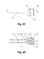
- Fig. 2 schematically illustrates an ignition head comprised by the electro-pyrotechnic igniter shown in Fig. 1 in, respectively, a perspective view ( Fig. 2A ), an exploded perspective view ( Fig. 2B ), a side view ( Fig. 2C ), a cross-sectional side view taken along line D-D indicated in Fig. 2C (Fig. 2D ), a top perspective view of the bridge filament support body and the bridge filament ( Fig. 2E ), and a bottom perspective view of the bridge filament support body and the bridge filament ( Fig. 2F ).
- Fig. 1 schematically illustrates an exemplary embodiment of an electro-pyrotechnic igniter 1 according to the present disclosure.
- Such an electro-pyrotechnic igniter 1 may include at least one ignition head 100.
- the embodiment of the electro-pyrotechnic igniter depicted in Fig. 1 includes two identical ignition heads 100, whose construction is schematically illustrated in more detail in Fig. 2 .
- the construction and operation of the ignition head 100 and the electro-pyrotechnic igniter 1 according to the present disclosure are described in general terms, where appropriate with reference to Figs. 1-2 .
- the ignition head 100 may be characterized as a non-pyrotechnic, electric ignition head 100. That is, the electrically powered ignition head 100 may itself be void of any pyrotechnic composition, and merely be configured to effect the ignition of a separate or external pyrotechnic charge 300 when it is brought in contact therewith, for instance when it is applied to ignite a cool gas generator charge in a cool gas generator or a booster-pellet in an electro-pyrotechnic igniter 1.
- some conventional ignition heads that are suitable for igniting pyrotechnic charges may differ from the presently disclosed ignition head 100.
- Such conventional ignition heads may in particular comprise a pyrotechnic primer charge or primer composition in which a bare/uncoated bridge wire of the ignition head is embedded.
- non-pyrotechnic ignition head 100 may include no such pyrotechnic primer charge, and that its bridge filament 120 may not be embedded in a pyrotechnic composition.
- any pyrotechnic composition to be ignited with the presently disclosed ignition head 100 may be separated from the bridge filament 120 by an electrically insulative, thermally conductive shield film 140, which may either form part of the ignition head 100 or part of the pyrotechnic charge 300.
- the ignition head 100 may include a housing 102.
- the housing 102 may in principle have any suitable shape, and be made from any suitable material.
- the housing 102 may be generally cylinder-jacket shaped.
- the housing 102 may preferably be made of metal or a metal alloy; preferred materials may include copper, brass, titanium, aluminum, and stainless steel.
- an outer surface of the housing 102 may define one or more circumferential grooves 103 in which an O-ring 114 may be provided.
- the housing 102 may further define an interior space 104, and a front opening 106 giving access to the interior space 104.
- the interior space 104 of the housing 102 may be fluidtightly sealed.
- the ignition head 100 may also include a bridge filament support body 130.
- the bridge filament support body 130 may in principle have any suitable shape, it may preferably take the form of a relatively thin plate, for example with an average thickness in the range of 0.2-2 mm.
- the bridge filament support body 130 may be circumferentially dimensioned such that it is approximately fittingly receivable in the front opening 106 of the housing 102, and be at least partially disposed therein such that an inner surface 132a of the bridge filament support body 130 faces the interior space 104 of the housing 102, and an outer frontal heating surface 132b of the bridge filament support body 130 faces outward from the interior space 104.
- the bridge filament support body 130 may serve to mechanically support a thin bridge filament 120, to electrically insulate the cross-overs 122 of the bridge filament 120 from each other and the housing 102, and to distribute heat produced by the bridge filament 120 over its frontal heating surface 132b.
- the bridge filament support body may preferably be (one or more of) substantially rigid, electrically insulative, heat resistant and thermally conductive.
- at least the frontal heating surface 132b of the bridge filament support body 130 may preferably be heat reflective, such that it reflects radiative heat given off the bridge filament's cross-overs 122.
- the frontal heating surface 132b may be provided with a heat reflective coating.
- the bridge filament support body 130 is at least partially made of a ceramic material, such as, for instance, silicon nitride (Si 3 N 4 ), silicon carbide (SiC), or aluminum oxide (Al 2 O 3 ).
- the frontal heating surface 132b may define a plurality of pairs of cross-over terminals 136, i.e. locations where the bridge filament 120 may pass, e.g. extend through or around, the bridge filament support body 130, from its back side 132a to its front side 132b and/or vice versa.
- the cross-over terminals 122 may take the form of through-holes or circumferentially bounded passages.
- the cross-over terminals 122 may take the form of indentations or recesses defined by an outer circumferential edge 134 of the frontal heating surface 134.
- the cross-over terminals 136 may be arranged such that straight lines interconnecting the terminals of respective pairs do not intersect each other.
- a bridge filament 120 may thus be provided on, e.g. wrapped around, the bridge filament support body 130 to define a plurality of cross-overs 122, each of which cross-overs 122 may be uniquely associated with a pair of cross-over terminals 136, and each of which may extend only between its associated pair of cross-over terminals 136 across the frontal heating surface 123b and without intersecting other cross-overs.
- the bridge filament 120 may be a relatively thin, relatively high-electrical-resistance element in the form of a continuous wire, ribbon (flat wire) or the like.
- the bridge filament 120 may be at least partially printed, e.g. screen-printed, onto the bridge filament support body 130, and/or be at least partially embedded therein.
- the bridge filament 120 may extend between a first end 120a and a second end 120b.
- the first and second ends 120a, 120b may typically be mutually electrically insulatively arranged within the interior space 104 of the housing 102 and thus on the inner side of the bridge filament support body 130.
- the bridge filament 120 may include at least one portion that extends over the frontal heating surface 132b of the bridge filament support body 130. It is understood that each such portion 122 of the bridge filament 120 that extends over the frontal heating surface, typically between two cross-over terminals 136, may be referred to as a 'cross-over' or 'cross-over portion'.
- the bridge filament 120 may be made of any suitable material, such as, for instance, a Nickel-Chromium (NiCr) alloy (e.g. Evanohm®), Alloy 815, Alloy 837, or Alloy 875.
- the first and second ends of the bridge filament 120 may be electrically conductively connected to respective relatively thick, relatively low-electrical-resistance lead wires 110.
- the lead wires 110 may be made from any suitable material, such as metals or alloys like copper, titanium or stainless steel, and be bare or uncoated.
- the lead wires 110 may exit the housing 102 via respective lead wire outlets 108, e.g including an opening in the (back of the) housing 102, which lead wire outlets 108 may provide for a respective fluidtight seals 112 between the housing 102 and the respective lead wire 110.
- the fluidtight seal may, for instance, take the form of a glass mass, which, in case the housing 102 and the lead wires 110 are made of metal, may provide for an hermetic glass-to-metal seal.
- the lead wires 110 may be made of a material with approximately the same (e.g. ⁇ 10%) thermal expansion coefficient as the material from which the housing 102 of the ignition head 100 is manufactured; this may ensure that no residual tension remains in the seal 112 when the ignition head 110 is subject to temperature variations during operation/use.
- the bridge filament 120 and in particular its cross-overs 122, may preferably not electrically conductively contact a pyrotechnic charge 300 to be ignited. Such direct electric contact may be prevented by interposing a shield film 140 in between the bridge filament 120 and the pyrotechnic charge 300.
- the shield film 140 may be applied to the bridge element 120, in particular to its cross-overs 122.
- the shield film 140 may, for instance, be 'wrapped around' at least a portion of the bridge element 120 as such and thus take the form of an electrically insulative jacket.
- the shield film 140 may take the form of a layer that overlays or covers at least part of the frontal heating surface 132b of the bridge filament support body 130, including the cross-overs 122 of the bridge filament 120 running over it. In this latter case, which is illustrated in the depicted embodiment (see Figs.
- the shield film 140 may have an inner surface 142a that faces the frontal heating surface 132b of the bridge filament support body 130, and an outer surface 142b that faces outward for direct physical contact with a pyrotechnic charge 300 to be ignited.
- the pyrotechnic charge 300 - typically instead of the bridge filament 140 and/or the frontal heating surface 132b - may be coated with a shield film 140.
- a shield film 140 may be applied to at least a portion of an outer surface of the pellet that is configured for contact with the (frontal heating surface 132b of the) ignition head 100. It is understood, however, that this embodiment is functionally equivalent to that in which a shield film 140 is applied to the frontal heating surface 132b of the bridge filament support body 130: in both cases, a shield film is interposed between the bridge filament's cross-overs 122 and the pyrotechnic composition of the pyrotechnic charge 300.
- the shield film 140 may be electrically insulative so as to prevent short-circuiting any cross-overs 122 of the bridge filament 120, and thermally conductive so as to enable the transfer of heat generated by the bridge filament 120 to the pyrotechnic charge 300.
- the shield film 140 may preferably have a heat transfer coefficient in the range of 240-24.000 W/m 2 K, and more preferably in the range of 1.250 - 4800 W/m 2 K.
- the shield film 140 may additionally be (i) chemically inert with respect to the chemical composition of a pyrotechnic charge 300 to be ignited (and its decomposition products) so as to enable the generation of clean gases, and/or (ii) low outgassing to enable the generation of clean gases and to render the ignition head 100 suitable for use under vacuum conditions, e.g. in space environments, and/or (iii) non-porous, and crack-resistant when subject to operational temperature variations, to prevent electrically conductive decomposition products of an ignited pyrotechnic charge from short-circuiting any cross-overs 122.
- Preferred materials for the shield film 140 may include Kapton®, in particular Kapton® MT and Kapton® MTB.
- Kapton is a registered trademark of DuPont, headquarted in Wilmington, Delaware, U.S.A.
- Other materials may include glass, glass-mica, glass-fiber, phenolic/bakelite, silicon, plastic, ceramics, and laminates of these materials.
- a thickness of the shield film 140 may typically be in the range of 5-500 ⁇ m, and, in case the shield film is at least partially made of Kapton®, preferably in the range of 25-125 ⁇ m.
- the shield film 140 may act as a thermal buffer in between the bridge filament 120 and the pyrotechnic composition of the pyrotechnic charge 300. As such, it may protect the bridge filament 120 from burning out early due to the development of heat upon ignition of the pyrotechnic charge 300. Moreover, the shield film 140 may act as an ignition retardation control, and as such as a lightweight safety mechanism that prevents accidental ignitions much like a conventional safe and arm device. It enables the transfer of heat from the cross-over portions 122 of the bridge filament 120, and preferably from the entire frontal heating surface 132b of the bridge filament support body 130, to the pyrotechnic composition of the pyrotechnic charge 300.
- the shield film may be provided with a heat transfer coefficient that - in a given, overall configuration - ensures that a minimum amount of electric ignition energy (or more accurately: a minimum average electric ignition energy supply rate (Watt) for a certain period of time) is required to effect ignition of the pyrotechnic charge 300. Since the thickness of the shield film 140 is an easily variable parameter, the presently disclosed ignition head is conveniently tunable for different ignition times.
- the ignition energy required to effect ignition of a pyrotechnic charge 300 may also depend on other factors, such as the amperage and voltage at which electric energy is provided to the ignition head 100, the thickness and type of the bridge filament 120, and the pyrotechnic composition of the pyrotechnic charge 300; in practice, these factors may preferably be considered in conjunction, and tailored to each other so as to achieve the desired ignition time.
- the electro-pyrotechnic igniter 1 may include a casing 200, at least one ignition head 100 of the above-described type, and at least one pyrotechnic charge 300.
- the casing 200 may in principle have any suitable shape, and be manufactured from any suitable material.
- the casing 200 may preferably be made of a metal or a metal alloy; preferred materials may include copper, titanium and stainless steel.
- the casing 200 may define an interior reaction chamber 214, which may be dimensioned to typically snugly receive the pyrotechnic charge 300.
- a flexible sheet 218, for instance made of rubber, may be provided to fix or clamp the pyrotechnic charge 300 within the reaction chamber 214, i.e. between the walls of the housing 200.
- the flexibility of the sheet 218 may accommodate a possible difference in thermal expansion of the housing 200 and the pyrotechnic charge 300, such that such a difference does not led to mechanical failure of the latter.
- the casing 200 may further define at least one exhaust orifice 204 via which the reaction chamber 214 is fluidly connected to an external environment of the electro-pyrotechnic igniter 1, e.g. the reaction chamber of a second-stage igniter.
- the exhaust orifice 204 may typically have a diameter in the order of millimeters.
- the casing 200 may define a plurality of exhaust orifices 204, e.g. three identical orifices angularly spaced 120° apart in a same plane.
- a plurality of exhaust orifices may improve the reliability of the igniter 1, since having multiple orifices 204 may reduce the chance of ignition failure (of a main charge) in case the pyrotechnic charge 300 of the igniter breaks or decomposes into different pieces which can clog of block an exhaust orifice 204.
- the number, size and arrangement of the exhaust orifices may be tailored to the application at hand.
- the casing 200 may comprise two parts: a main body 202a, and a nozzle plate 202b; the latter may include the at least one exhaust orifice 204.
- the reaction chamber 214 is easily accessible, which allows for installation, removal and/or replacement of the pyrotechnic charge 300 during assembly or subsequent use.
- the nozzle plate 202b and the main body 202a may be preferably be connectable to each other by releaseable fastening means, such as screws 206.
- a mounting surface of the igniter 1 which may typically comprise the normally planar outer surface of the casing 200 including the at least one exhaust orifice 204, may include at least one endless groove in which a respective O-ring 210, 212 may be provided.
- the at least one groove and O-ring 210, 212 may preferably encircle the at least one exhaust orifice 204 in order to enable the fluidtight fluid communication with another chamber provided in the body onto which the igniter 1 may be mounted, such as the aforementioned reaction chamber of a second-stage igniter.
- multiple grooves and respective O-rings may be provided.
- one groove and O-ring 210 may be provided in the mounting surface of the main body 202a of the casing 200 to encircle a seam between the main body 202a and the nozzle plate 202b, while another groove and O-ring 212 may be provided in the nozzle plate 202b to encircle the at least one exhaust orifice 204.
- the igniter 1 may include a non-reclosing pressure relief device 218, such as a burst disc.
- the non-reclosing pressure relief device which in itself may be of a conventional design, may be arranged to close off the at least one exhaust orifice 204 in the nozzle plate 202b, and be configured to open it once a predetermined pressure has developed within the reaction chamber 214.
- the pressure at which the non-reclosing pressure relief device is configured to open the at least one exhaust orifice 204 may preferably be chosen such that further autonomous decomposition of the pyrotechnic charge 300 is facilitated and effectively guaranteed.
- the electro-pyrotechnic igniter 1 may be provided with a plurality of ignition heads 100 to provide for redundancy and reliability, which is a practical requirement for space applications given the lack of opportunities to repair or replace malfunctioning parts.
- the frontal heating surfaces 132b of the ignition heads may preferably (pairwise) face each other and clasp the pyrotechnic charge 300 in between them, so as to enable ignition of the charge from opposite sides.
- the pyrotechnic charge 300 may typically be provided in the form of a pellet that is at least partially made of a certain pyrotechnic composition, such as, for instance, boron potassium nitrate (BKNO 3 ). As mentioned, some embodiments of the pyrotechnic charge 300 may be at least partially coated with a non-pyrotechnic, electrically insulative and thermally conductive shield film. The pyrotechnic charge 300 may then be installed in the reaction chamber 214 such that the shield film is interposed between the cross-overs 122 of the bridge filament 120 of the at least one ignition head 100 and the pyrotechnic composition of the charge.
- a certain pyrotechnic composition such as, for instance, boron potassium nitrate (BKNO 3 ).
- BKNO 3 boron potassium nitrate
- the electro-pyrotechnic igniter 1 may be integrated into an ignition system that may further include a power supply to which the at least one ignition head 100 of the electro-pyrotechnic igniter may be operably connected.
- the power supply may typically be configured to provide electrical energy at a certain amperage and voltage, and the ignition system as a whole may preferably be configured such that an ignition energy to be supplied by the power supply at said amperage and voltage in order to ignite the pyrotechnic charge is at least 10 Joules, for instance in the safe range of 10-200 Joules, and preferably in the range of 25-100 Joules.
Landscapes
- Engineering & Computer Science (AREA)
- General Engineering & Computer Science (AREA)
- Air Bags (AREA)
Priority Applications (4)
| Application Number | Priority Date | Filing Date | Title |
|---|---|---|---|
| EP12196435.7A EP2743632A1 (fr) | 2012-12-11 | 2012-12-11 | Allumeur électropyrotechnique miniature et tête d'allumage pour celui-ci |
| PCT/NL2013/050882 WO2014092565A1 (fr) | 2012-12-11 | 2013-12-10 | Allumeur électro-pyrotechnique miniature, et tête d'allumage pour celui-ci |
| EP13808267.2A EP2932186B1 (fr) | 2012-12-11 | 2013-12-10 | Allumeur électropyrotechnique miniature et tête d'allumage pour celui-ci |
| US14/650,805 US20150308805A1 (en) | 2012-12-11 | 2013-12-10 | Miniature electro-pyrotechnic igniter, and ignition head for the same |
Applications Claiming Priority (1)
| Application Number | Priority Date | Filing Date | Title |
|---|---|---|---|
| EP12196435.7A EP2743632A1 (fr) | 2012-12-11 | 2012-12-11 | Allumeur électropyrotechnique miniature et tête d'allumage pour celui-ci |
Publications (1)
| Publication Number | Publication Date |
|---|---|
| EP2743632A1 true EP2743632A1 (fr) | 2014-06-18 |
Family
ID=47504657
Family Applications (2)
| Application Number | Title | Priority Date | Filing Date |
|---|---|---|---|
| EP12196435.7A Withdrawn EP2743632A1 (fr) | 2012-12-11 | 2012-12-11 | Allumeur électropyrotechnique miniature et tête d'allumage pour celui-ci |
| EP13808267.2A Not-in-force EP2932186B1 (fr) | 2012-12-11 | 2013-12-10 | Allumeur électropyrotechnique miniature et tête d'allumage pour celui-ci |
Family Applications After (1)
| Application Number | Title | Priority Date | Filing Date |
|---|---|---|---|
| EP13808267.2A Not-in-force EP2932186B1 (fr) | 2012-12-11 | 2013-12-10 | Allumeur électropyrotechnique miniature et tête d'allumage pour celui-ci |
Country Status (3)
| Country | Link |
|---|---|
| US (1) | US20150308805A1 (fr) |
| EP (2) | EP2743632A1 (fr) |
| WO (1) | WO2014092565A1 (fr) |
Cited By (1)
| Publication number | Priority date | Publication date | Assignee | Title |
|---|---|---|---|---|
| CN117663927A (zh) * | 2023-12-08 | 2024-03-08 | 重庆云铭科技股份有限公司 | 一种保护刚性桥丝的pcb |
Families Citing this family (5)
| Publication number | Priority date | Publication date | Assignee | Title |
|---|---|---|---|---|
| CA3152207A1 (fr) | 2019-09-06 | 2021-03-11 | R3 IOT Limited | Passerelle de communication avec un dispositif d'embarquement, et procedes associes |
| CN112880494A (zh) * | 2021-03-31 | 2021-06-01 | 东莞市安林电子有限公司 | 一种新型电子雷管点火元件、加工工艺及电子雷管 |
| KR102454541B1 (ko) * | 2022-07-21 | 2022-10-17 | 국방과학연구소 | 고고도 듀얼펄스 모타용 안전점화장치 |
| CN121729604A (zh) * | 2023-08-22 | 2026-03-24 | 眼镜蛇点火系统公司 | 嵌入式电子烟花点火器 |
| US12584718B2 (en) | 2023-08-22 | 2026-03-24 | Cobra Firing Systems | Embedded electronic firework igniter |
Citations (7)
| Publication number | Priority date | Publication date | Assignee | Title |
|---|---|---|---|---|
| US3059576A (en) * | 1958-09-26 | 1962-10-23 | Conax Corp | Electrically fired detonator |
| US3134329A (en) * | 1962-05-10 | 1964-05-26 | Thiokol Chemical Corp | Exploding bridgewire coating |
| FR2053791A5 (fr) * | 1969-07-18 | 1971-04-16 | Commissariat Energie Atomique | |
| EP0779492A2 (fr) * | 1995-12-15 | 1997-06-18 | Morton International, Inc. | Initiateur pour gonfleur avec dispositif de protection contre les décharges électrostatiques à diode zener |
| US20020096078A1 (en) * | 2001-01-22 | 2002-07-25 | Goosen Adriaan J. | Initiating device for an electronic detonator |
| US20040164069A1 (en) * | 2003-02-26 | 2004-08-26 | Hirtenberger-Schaffler Automotive Zunder Ges. M.B.H. | Heating element for igniting a pyrotechnical charge |
| EP1662224A1 (fr) * | 2004-11-30 | 2006-05-31 | Weatherford/Lamb, Inc. | Initiateur non-explosif à deux composantes |
Family Cites Families (5)
| Publication number | Priority date | Publication date | Assignee | Title |
|---|---|---|---|---|
| US4259564A (en) * | 1977-05-31 | 1981-03-31 | Nippon Electric Co., Ltd. | Integrated thermal printing head and method of manufacturing the same |
| US5254838A (en) * | 1987-09-14 | 1993-10-19 | Nippon Koki Co., Ltd. | Igniter for electric ignition systems |
| US5088413A (en) * | 1990-09-24 | 1992-02-18 | Schlumberger Technology Corporation | Method and apparatus for safe transport handling arming and firing of perforating guns using a bubble activated detonator |
| FR2790078B1 (fr) * | 1999-02-18 | 2004-11-26 | Livbag Snc | Allumeur electropyrotechnique a securite d'allumage renforcee |
| US7571679B2 (en) * | 2006-09-29 | 2009-08-11 | Reynolds Systems, Inc. | Energetic material initiation device having integrated low-energy exploding foil initiator header |
-
2012
- 2012-12-11 EP EP12196435.7A patent/EP2743632A1/fr not_active Withdrawn
-
2013
- 2013-12-10 EP EP13808267.2A patent/EP2932186B1/fr not_active Not-in-force
- 2013-12-10 US US14/650,805 patent/US20150308805A1/en not_active Abandoned
- 2013-12-10 WO PCT/NL2013/050882 patent/WO2014092565A1/fr not_active Ceased
Patent Citations (7)
| Publication number | Priority date | Publication date | Assignee | Title |
|---|---|---|---|---|
| US3059576A (en) * | 1958-09-26 | 1962-10-23 | Conax Corp | Electrically fired detonator |
| US3134329A (en) * | 1962-05-10 | 1964-05-26 | Thiokol Chemical Corp | Exploding bridgewire coating |
| FR2053791A5 (fr) * | 1969-07-18 | 1971-04-16 | Commissariat Energie Atomique | |
| EP0779492A2 (fr) * | 1995-12-15 | 1997-06-18 | Morton International, Inc. | Initiateur pour gonfleur avec dispositif de protection contre les décharges électrostatiques à diode zener |
| US20020096078A1 (en) * | 2001-01-22 | 2002-07-25 | Goosen Adriaan J. | Initiating device for an electronic detonator |
| US20040164069A1 (en) * | 2003-02-26 | 2004-08-26 | Hirtenberger-Schaffler Automotive Zunder Ges. M.B.H. | Heating element for igniting a pyrotechnical charge |
| EP1662224A1 (fr) * | 2004-11-30 | 2006-05-31 | Weatherford/Lamb, Inc. | Initiateur non-explosif à deux composantes |
Cited By (1)
| Publication number | Priority date | Publication date | Assignee | Title |
|---|---|---|---|---|
| CN117663927A (zh) * | 2023-12-08 | 2024-03-08 | 重庆云铭科技股份有限公司 | 一种保护刚性桥丝的pcb |
Also Published As
| Publication number | Publication date |
|---|---|
| EP2932186B1 (fr) | 2017-10-04 |
| EP2932186A1 (fr) | 2015-10-21 |
| US20150308805A1 (en) | 2015-10-29 |
| WO2014092565A1 (fr) | 2014-06-19 |
Similar Documents
| Publication | Publication Date | Title |
|---|---|---|
| EP2932186B1 (fr) | Allumeur électropyrotechnique miniature et tête d'allumage pour celui-ci | |
| US4484523A (en) | Detonator, solid state type I film bridge | |
| US3420174A (en) | Pulse sensitive electro-explosive device | |
| US7574960B1 (en) | Ignition element | |
| GB1593677A (en) | Propellant charge igniter | |
| WO2007029682A1 (fr) | Pont semi-conducteur, allumeur et générateur de gaz | |
| US9829289B1 (en) | Disposable, miniature internal optical ignition source | |
| CA1319962C (fr) | Allumeur pour systemes d'allumage electrique | |
| US9909847B1 (en) | Disposable, miniature internal optical ignition source | |
| US3625767A (en) | Thermal battery | |
| KR101708768B1 (ko) | 내압 마개를 구비하는 압력 카트리지 | |
| JP4816170B2 (ja) | ホローカソード | |
| JP4633522B2 (ja) | 点火器組立体 | |
| RU2413341C2 (ru) | Тепловой источник тока | |
| US3125025A (en) | Pyrotechnic igniter | |
| CN111174652B (zh) | 一种起爆电阻及爆破装置 | |
| CN1326161C (zh) | 用于电能传输网络中的过电压防护放电器 | |
| JP5567080B2 (ja) | 薄型イグナイタおよびその製造方法 | |
| US10415942B1 (en) | Disposable, miniature internal optical ignition source | |
| KR101583681B1 (ko) | 소화기 | |
| KR101623337B1 (ko) | 소화기의 기폭용 발열체 및 이에 의한 소화기용 기폭장치 | |
| RU2408113C1 (ru) | Тепловой химический источник тока | |
| US10627200B1 (en) | Disposable, miniature internal optical ignition source | |
| JPS61171065A (ja) | 熱電池 | |
| KR101593393B1 (ko) | 소화기용 기폭장치 및 이에 의한 소화기 |
Legal Events
| Date | Code | Title | Description |
|---|---|---|---|
| PUAI | Public reference made under article 153(3) epc to a published international application that has entered the european phase |
Free format text: ORIGINAL CODE: 0009012 |
|
| 17P | Request for examination filed |
Effective date: 20121211 |
|
| AK | Designated contracting states |
Kind code of ref document: A1 Designated state(s): AL AT BE BG CH CY CZ DE DK EE ES FI FR GB GR HR HU IE IS IT LI LT LU LV MC MK MT NL NO PL PT RO RS SE SI SK SM TR |
|
| AX | Request for extension of the european patent |
Extension state: BA ME |
|
| STAA | Information on the status of an ep patent application or granted ep patent |
Free format text: STATUS: THE APPLICATION IS DEEMED TO BE WITHDRAWN |
|
| 18D | Application deemed to be withdrawn |
Effective date: 20141219 |