EP2743664A2 - Messvorrichtung des Motordrehmoments in einem Zyklus - Google Patents
Messvorrichtung des Motordrehmoments in einem Zyklus Download PDFInfo
- Publication number
- EP2743664A2 EP2743664A2 EP13197178.0A EP13197178A EP2743664A2 EP 2743664 A2 EP2743664 A2 EP 2743664A2 EP 13197178 A EP13197178 A EP 13197178A EP 2743664 A2 EP2743664 A2 EP 2743664A2
- Authority
- EP
- European Patent Office
- Prior art keywords
- sensor
- circuit
- pawl
- hub
- engine
- Prior art date
- Legal status (The legal status is an assumption and is not a legal conclusion. Google has not performed a legal analysis and makes no representation as to the accuracy of the status listed.)
- Withdrawn
Links
- 238000005259 measurement Methods 0.000 claims description 7
- 230000007423 decrease Effects 0.000 claims description 5
- 238000004146 energy storage Methods 0.000 claims description 3
- 238000012545 processing Methods 0.000 description 15
- 230000005540 biological transmission Effects 0.000 description 9
- 238000004891 communication Methods 0.000 description 5
- 239000000463 material Substances 0.000 description 5
- 238000000034 method Methods 0.000 description 3
- 238000007493 shaping process Methods 0.000 description 3
- 238000012360 testing method Methods 0.000 description 3
- 230000003321 amplification Effects 0.000 description 2
- 230000006835 compression Effects 0.000 description 2
- 238000007906 compression Methods 0.000 description 2
- 239000003292 glue Substances 0.000 description 2
- 238000003199 nucleic acid amplification method Methods 0.000 description 2
- 238000012549 training Methods 0.000 description 2
- 229910000838 Al alloy Inorganic materials 0.000 description 1
- 229920001651 Cyanoacrylate Polymers 0.000 description 1
- MWCLLHOVUTZFKS-UHFFFAOYSA-N Methyl cyanoacrylate Chemical compound COC(=O)C(=C)C#N MWCLLHOVUTZFKS-UHFFFAOYSA-N 0.000 description 1
- 235000014676 Phragmites communis Nutrition 0.000 description 1
- 229910000831 Steel Inorganic materials 0.000 description 1
- 238000004873 anchoring Methods 0.000 description 1
- 239000003990 capacitor Substances 0.000 description 1
- 239000004020 conductor Substances 0.000 description 1
- 239000003822 epoxy resin Substances 0.000 description 1
- 239000000945 filler Substances 0.000 description 1
- 238000012986 modification Methods 0.000 description 1
- 230000004048 modification Effects 0.000 description 1
- 230000002093 peripheral effect Effects 0.000 description 1
- 229920000647 polyepoxide Polymers 0.000 description 1
- 238000011084 recovery Methods 0.000 description 1
- 238000005070 sampling Methods 0.000 description 1
- 230000035945 sensitivity Effects 0.000 description 1
- 239000010959 steel Substances 0.000 description 1
- 230000001360 synchronised effect Effects 0.000 description 1
- 230000000007 visual effect Effects 0.000 description 1
Images


Classifications
-
- B—PERFORMING OPERATIONS; TRANSPORTING
- B62—LAND VEHICLES FOR TRAVELLING OTHERWISE THAN ON RAILS
- B62J—CYCLE SADDLES OR SEATS; AUXILIARY DEVICES OR ACCESSORIES SPECIALLY ADAPTED TO CYCLES AND NOT OTHERWISE PROVIDED FOR, e.g. ARTICLE CARRIERS OR CYCLE PROTECTORS
- B62J45/00—Electrical equipment arrangements specially adapted for use as accessories on cycles, not otherwise provided for
- B62J45/40—Sensor arrangements; Mounting thereof
- B62J45/41—Sensor arrangements; Mounting thereof characterised by the type of sensor
- B62J45/411—Torque sensors
-
- B—PERFORMING OPERATIONS; TRANSPORTING
- B60—VEHICLES IN GENERAL
- B60W—CONJOINT CONTROL OF VEHICLE SUB-UNITS OF DIFFERENT TYPE OR DIFFERENT FUNCTION; CONTROL SYSTEMS SPECIALLY ADAPTED FOR HYBRID VEHICLES; ROAD VEHICLE DRIVE CONTROL SYSTEMS FOR PURPOSES NOT RELATED TO THE CONTROL OF A PARTICULAR SUB-UNIT
- B60W10/00—Conjoint control of vehicle sub-units of different type or different function
- B60W10/04—Conjoint control of vehicle sub-units of different type or different function including control of propulsion units
- B60W10/08—Conjoint control of vehicle sub-units of different type or different function including control of propulsion units including control of electric propulsion units, e.g. motors or generators
-
- B—PERFORMING OPERATIONS; TRANSPORTING
- B62—LAND VEHICLES FOR TRAVELLING OTHERWISE THAN ON RAILS
- B62J—CYCLE SADDLES OR SEATS; AUXILIARY DEVICES OR ACCESSORIES SPECIALLY ADAPTED TO CYCLES AND NOT OTHERWISE PROVIDED FOR, e.g. ARTICLE CARRIERS OR CYCLE PROTECTORS
- B62J45/00—Electrical equipment arrangements specially adapted for use as accessories on cycles, not otherwise provided for
- B62J45/40—Sensor arrangements; Mounting thereof
- B62J45/41—Sensor arrangements; Mounting thereof characterised by the type of sensor
- B62J45/412—Speed sensors
-
- B—PERFORMING OPERATIONS; TRANSPORTING
- B62—LAND VEHICLES FOR TRAVELLING OTHERWISE THAN ON RAILS
- B62J—CYCLE SADDLES OR SEATS; AUXILIARY DEVICES OR ACCESSORIES SPECIALLY ADAPTED TO CYCLES AND NOT OTHERWISE PROVIDED FOR, e.g. ARTICLE CARRIERS OR CYCLE PROTECTORS
- B62J45/00—Electrical equipment arrangements specially adapted for use as accessories on cycles, not otherwise provided for
- B62J45/40—Sensor arrangements; Mounting thereof
- B62J45/42—Sensor arrangements; Mounting thereof characterised by mounting
- B62J45/423—Sensor arrangements; Mounting thereof characterised by mounting on or besides the wheel
-
- G—PHYSICS
- G01—MEASURING; TESTING
- G01L—MEASURING FORCE, STRESS, TORQUE, WORK, MECHANICAL POWER, MECHANICAL EFFICIENCY, OR FLUID PRESSURE
- G01L3/00—Measuring torque, work, mechanical power, or mechanical efficiency, in general
- G01L3/02—Rotary-transmission dynamometers
- G01L3/04—Rotary-transmission dynamometers wherein the torque-transmitting element comprises a torsionally-flexible shaft
- G01L3/10—Rotary-transmission dynamometers wherein the torque-transmitting element comprises a torsionally-flexible shaft involving electric or magnetic means for indicating
-
- G—PHYSICS
- G01—MEASURING; TESTING
- G01L—MEASURING FORCE, STRESS, TORQUE, WORK, MECHANICAL POWER, MECHANICAL EFFICIENCY, OR FLUID PRESSURE
- G01L3/00—Measuring torque, work, mechanical power, or mechanical efficiency, in general
- G01L3/02—Rotary-transmission dynamometers
- G01L3/14—Rotary-transmission dynamometers wherein the torque-transmitting element is other than a torsionally-flexible shaft
- G01L3/1478—Rotary-transmission dynamometers wherein the torque-transmitting element is other than a torsionally-flexible shaft involving hinged levers
Definitions
- the present invention relates to a device for measuring the engine torque and / or the driving power of a cycle wheel, and a cycle wheel hub equipped with such a device.
- the measurement of the driving power of a bicycle wheel is of interest in many cases, for example to evaluate the performance of a cyclist during a training.
- the knowledge at all times of the motor power provided by the cyclist is likely to help cyclists to optimize their practice. It allows them to better manage their effort and pedaling, training or during a race.
- the driving power provided by the cyclist can be obtained by multiplying the engine torque, transmitted by the cyclist to the driving wheel, by the angular speed of this wheel.
- the publication W02011 / 066075 discloses a bicycle rear wheel hub comprising a device for measuring the driving torque exerted on the driving wheel of the bicycle.
- a device for measuring the engine torque and / or the engine power developed on a hub body by a freewheel body connected to the hub body by a freewheel mechanism comprising at least one sensor deformation and / or stress on or integrated with at least one pawl of said mechanism and a circuit connected to the sensor for determining the driving torque and / or the driving power.
- the senor comprises at least one strain gauge on said pawl.
- At least two deformation and / or stress sensors are disposed on or integrated with said pawl.
- the senor comprises at least one electromechanical microsystem integrated in the pawl.
- the mechanism comprises a plurality of pawls, the device comprising at least one deformation and / or strain sensor on or integrated with each pawl.
- the device comprises a power supply system of said circuit and / or said sensor comprising at least one solar panel and an energy storage device.
- the device further comprises a sensor for determining the angular velocity of the hub body.
- the device comprises a first motor torque determining circuit and a second driving power determining circuit distinct from the first circuit.
- the first circuit transmits data to the second circuit via a wireless link.
- a cycle hub comprising a free wheel body, a hub body, a ratchet free wheel mechanism, and a device, as defined above, for measuring the engine torque and / or the engine power developed. on the hub body by the freewheel body.
- the senor is located in a recess provided on the surface of the pawl.
- a cycle drive wheel in particular a bicycle, a motorized bicycle, a tandem or a tricycle, with a device for measuring the engine torque supplied by the cyclist to drive the driving wheel in rotation.
- a device for measuring the engine torque supplied by the cyclist to drive the driving wheel in rotation in general the rear wheel of the cycle, in particular to determine the motive power provided by the cyclist.
- the torque measuring device comprises a test body equipped with strain gauges and disposed in the casing of the rear wheel gears.
- a disadvantage of this device is that it requires the use a specific test body. This results in significant modifications of an existing hub to install the measuring device.
- a housing must be provided to receive the test body of the measuring device, which leads to increase the mass and size of the hub of the rear wheel. This can further degrade the visual appearance of the cycle.
- an object of an embodiment is to overcome all or part of the disadvantages of cycle wheel hubs described above equipped with torque and / or power measuring devices.
- Another object of an embodiment is that the device for measuring the engine torque and / or the driving power of a cycle drive wheel changes little the structure of the existing drive wheel hubs.
- Another object of an embodiment is that the measuring device has a small footprint.
- Another object of an embodiment is that the measuring device can easily be adapted to the existing cycle wheel hubs.
- the Figures 1 to 3 represent an embodiment of a hub 5 of a driving wheel of a cycle, for example the rear wheel of a bicycle.
- the hub 5 comprises a hub body 10 having a cylindrical opening 12 of axis D.
- the opening 12 is intended to receive a hollow shaft D axis, not shown, attached to the frame of the bicycle.
- the hub body 10 is rotatably mounted around this shaft.
- the hub body 10 comprises a cylindrical central portion 14 and two lateral cheeks or bulges 16 and 18 of diameter greater than the diameter of the central portion 14.
- the cheeks 16, 18 are provided to provide anchoring points to the spokes, not shown of the wheel, these spokes being further mounted on a rim.
- the hub body 10 comprises a nozzle 20 intended to receive a free wheel body 22.
- the bulge 18 is located between the middle portion 14 and the tip 20.
- the freewheel body 22 comprises a cylindrical and fluted outer surface 24 which is provided to receive a gear box, not shown, also called pinion cassette.
- the gearbox is engaged with the bicycle chain and is rotated when the cyclist actuates the pedal of the bicycle.
- the freewheel body 22 is traversed by an opening 26 of axis D.
- the nozzle 20 is disposed in the opening 26 and bearings, not shown, are interposed between the nozzle 20 and the wheel body free 22.
- a unidirectional free wheel mechanism 28 provides the connection between the hub body 10 and the freewheel body 22.
- the freewheel mechanism 28 comprises at least one pawl 30, generally at least two pawls.
- each pawl 30 is disposed in a housing 32 provided in the nozzle 20.
- the inner surface of the opening 26 of the nozzle 20 comprises notches or teeth 34 all around the mouthpiece opposite.
- each pawl may be arranged in a recess provided in the freewheel body 22 and the outer surface of the end piece 20 may comprise notches or teeth all around the end-piece opposite the ratchets. 30.
- each housing 32 comprises a flat bottom 36, two flat lateral walls 38, a flat rear wall 40 and two recesses 42, each depression 42 being situated between one of the side walls 38 and the rear wall 40.
- the Figures 4 and 5 represent the ratchet 30 in more detail.
- the pawl 30 comprises an upper wall 44, a flat bottom wall 46, a rounded front wall 48 connecting the front edge of the upper wall 44 to the front edge of the lower wall 46, a flat rear wall 50 connecting the rear edge of the upper wall 44 to the rear edge of the bottom wall 46 and side walls 52 connecting the side edges of the top wall 44 to the side edges of the bottom wall 46.
- the ratchet 30 further comprises lugs 54 projecting on either side of the ratchet 30 from the side walls 52.
- Each pawl 30 is pivotably mounted in the housing 32 about an axis parallel to the axis D extending substantially at the lugs 54.
- the pawls 30 are slaved to cooperate with the notches or teeth 34 provided on the internal surface of the opening 26 of the nozzle 20.
- Each pawl 30 is permanently held in abutment against the teeth 34 by a not shown elastic return means, for example a spring.
- the maximum thickness of the pawl 30 is about 3 mm
- the distance between the front wall 48 and the rear wall 50 is about 10 mm
- the distance between the side walls 52 is about 10 mm.
- the pawls 30 selectively secure the bodies 10 and 22 when the cyclist exerts a force to rotate the freewheel body 22 by means of a pedal connected to the gear box by a chain.
- the freewheel body 22 then rotates the hub body 10.
- the pawls 30 do not prevent the rotation of the hub body 10 continues.
- the driving wheel of the bicycle can then rotate without the crankset being rotated.
- the pawl 30 includes a recess 56 provided on the upper wall 44.
- the recess 56 has a maximum depth of less than or equal to 0.8 mm.
- a force and / or deformation sensor 60 is disposed in the recess 56.
- the sensor 60 is glued to the bottom of the recess 56 by a diaper glue 62, especially a cyanoacrylate glue.
- the remainder of the recess 56 may be filled by a filler material 64, for example an epoxy resin.
- the sensor 60 is connected by electrical conductors 66, for example electrical wires, to a processing circuit, not shown.
- An opening 68 which opens into the central opening 12 of the hub body, is provided along the wall 38 of the housing 32.
- the opening 68 allows the passage of the wires 66 in the central opening 12.
- An opening 70 which opens into the central opening 12 of the hub body, is provided in the middle portion 14 of the hub body 10 and makes it possible to pass wires from the central opening 12 towards the outside of the hub body 10.
- a force / strain sensor is also provided on the lower wall 46 of the pawl 30 and / or on the side walls 52.
- at least one force / strain sensor is provided for at least two pawls, preferably for each pawl 30 of the freewheel mechanism 28.
- the senor 60 comprises a strain gauge.
- the strain gauge is adapted to reflect the deformation of the pawl in electrical resistance variation.
- the strain gauge is arranged to detect a deformation of the pawl 30 in a longitudinal direction, that is to say substantially perpendicular to the rear wall 50.
- a plurality of strain gauges are disposed on the wall 44 in different orientations.
- the senor is made in part or totally integrated way to the pawl 30. It can then include an electromechanical microsystem or MEMS (acronym for Microelectromechanical System).
- MEMS Microelectromechanical System
- the pawl 30 is made of a material such as an aluminum alloy or steel. These materials have a high yield strength. Of course, any other suitable material is suitable.
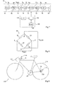
- the figure 6 represents, in the form of a schemablock, an embodiment of a system 70 for measuring the motive power supplied by the cyclist.
- the circuit 72 determines the motor torque C M from the force F exerted by the free wheel body 22 on the pawl 30 when the freewheel body 22 rotates the hub body 10 and obtained from the measurement provided by the sensor 60.
- the factor A reflects the fact that the direction of the force F measured by the sensor 60 may not be exactly perpendicular to the line perpendicular to the axis D and substantially passing through the point of application of the force F, that is to say substantially at the front wall 48 of the ratchet 30.
- the senor 60 is adapted to provide a signal representative of the deformation ⁇ of the pawl 30.
- the relative variation of the resistance of the strain gauge 60 is proportional, to the gauge factor, to the variation in the relative length of the gauge, and thus also to the variation in relative length. the part of the pawl that supports the strain gauge.
- a gauge 60 is selected which has a high gage factor, to obtain a signal of greater amplitude and thus improve the sensitivity of the sensor 60.
- the angular velocity sensor 74 detects the rotational speed ⁇ of the rear or front wheel of the bicycle as is known in the art.
- the angular speed sensor 74 may be a Reed-type cell adapted to measure the angular speed of the hub 5.
- the Reed cell detects each revolution of the hub around the shaft on which the hub is mounted. means of a magnet disposed in a notch in the shaft, which provides a measure of the angular velocity of the wheel.
- the system 78 may include a display screen and / or a memory for storing data.
- the circuit 76 is then adapted to display the driving power P M determined on the display screen and / or to store in the memory the driving power value P M determined.
- the circuit 76 can determine additional data, in addition to the driving power P M , from the engine torque C M and / or the speed of rotation ⁇ . For example, the circuit 76 can determine the speed of the bicycle, distance traveled and travel time as well as average values, such as average power, average speed, etc.
- circuits 72 and 76 are at least partially merged.
- the link 73, the link 75 and / or the link 79 may be wired links or wireless links.
- data transmission over wireless links implements wireless data exchange methods. This may be the method known as ANT or methods based on the IEEE 802.15.4 standard, including the communication protocol known as Zigbee, or the IEEE 802.15.1 standard, including the communication known as Bluetooth.
- the wired links may comprise a rotating commutator in the case where signals must be transmitted between two parts that are mobile in rotation relative to one another.
- the motor torque measuring circuit 72, the angular velocity sensor 74, the driving power determining circuit 76 and the system 78 may be arranged at different locations on the bicycle.
- the torque measuring circuit 72 may be located at the hub 5 of the rear wheel
- the drive power determining circuit 76 and the data display system 78 may be located on the handlebar of the bicycle and the speed sensor 74 can be located on the stays of the cycle, for the measurement of the speed of rotation of the rear wheel, or on the fork of the cycle, for the measurement of the speed of rotation of the front wheel .
- the figure 7 represents, partially and schematically, an embodiment of the circuit 72 for measuring the engine torque C M , in the case where the link 73 is a wireless link.
- the shaping circuit 80 comprises a Wheatstone bridge 86 connected to the strain gauge 60.
- the Wheatstone bridge 86 provides a signal S WH to a analog amplifier 88 which amplifies the signal S WH measured by the bridge 86.
- the amplifier 88 supplies the analog signal SA to the processing circuit 82.
- the senor 60 is a force sensor adapted to measure the force applied by the freewheel body 22 to the pawl 30 when the freewheel body 22 is rotated by the cyclist. In this case, if the signal provided by the sensor 60 is directly representative of the force applied to the pawl 30, the Wheatstone bridge 86 may not be present.
- the processing circuit 82 comprises an analog / digital converter 90 (A / D) which converts the analog signal SA into a digital signal S D.
- the processing circuit 82 further comprises a module 92 (Processor) receiving the signal S D and supplying a digital signal S ' C representative of the engine torque C M.
- the processing circuit 82 comprises, for example, a microcontroller executing software instructions, and a memory. It can also be an electronic circuit configured to determine the engine torque C M.
- the processing circuit 82 further comprises a module 94 (Interface) for shaping the signal S ' C for the to transmit to the transmission circuit 84.
- the module 94 is adapted to shape the digital signal S ' C for transmission on a serial synchronous data bus or SPI (English signal for Serial Peripheral Interface).
- the transmission circuit 84 may comprise a radiofrequency transmitter 96 (RF) connected to an antenna 98.
- RF radiofrequency transmitter
- the values of the signal S C supplied by the processing circuit 82 may be transmitted via the transmitter RF 96 at antenna 98 for a 2.4 GHz radio frequency transmission according to the ANT wireless communication protocol.
- the power supply of the torque measuring circuit 72 is performed by a power supply circuit 100.
- the supply circuit 100 comprises a storage module 102 (storage), for example a battery or a capacitor, photovoltaic panels 104 (PV) and a power management module 106 (Energy Unit) connected to the energy storage module 102 and the photovoltaic panels 104.
- the module 106 is adapted to provide a substantially constant voltage at the circuit 72 from the energy provided by the storage means 102 and / or photovoltaic panels 104.
- the energy management module 106 is further adapted to recharge the storage means 102 from the energy provided by the photovoltaic panels 104.
- the photovoltaic panels 104 are, for example, placed at the rim of the rear wheel and / or spokes of the rear wheel.
- the power supply circuit 100 may furthermore comprise another energy source, in addition to or instead of the photovoltaic panels 104. It is, for example, a recovery system for energy associated with the rear wheel.
- circuits 80, 82, 84, 102 and 106 may be arranged in a housing located in or on the middle part 14 of the hub body 10.
- the processing circuit 92 can, in addition, receive from the sensor of angular velocity 74 a signal representative of the angular speed of the wheels and may, in addition to the engine torque C M, determine the engine power P M.
- the ratchets rotate the freewheel body 22 in rotation with the hub body 10, and the hub body 10 is rotated about the axis D.
- the ratchet 30 is deformed and varies the resistance of the strain gauge 60, which enables the processing circuitry 92 to calculate the value of the engine torque C M, based on the signal supplied by the Wheatstone bridge 86.
- the pawl 30 works essentially in compression when the freewheel body 22 drives the hub body 10 in rotation.
- the sensor 60 is not biased. It is only when a driving torque is transmitted that the sensor 60 is stressed in compression.
- all the elements of the device 72 are set to cancel the unbalance of the Wheatstone bridge in the absence of bias and to also cancel the imbalances of the entire amplification chain and signal processing.
- the processing circuit 92 automatically detects the freewheel phases by studying the instantaneous variations of the torque. Indeed, during a pedaling cycle, the torque transmitted by the cyclist passes through two maximums, corresponding to the positions where the right and left crank cranks are substantially at an angle of 60 ° with the vertical, and two minimums, when the cranks are in the low position.
- the processing circuit 92 is adapted to detect these repeated variations of the engine torque C M. When there is no more variation, the processing circuit 92 deduces that the bicycle is freewheeling. The processing circuit 72 can then control the adjustment of operating parameters of the elements of the device 72 (variable amplification gain, variable resistances, etc.) for setting the zero of the device 72.
- the figure 8 represents an embodiment of the Wheatstone bridge 86.
- the Wheatstone bridge 86 comprises four nodes A, B, C and D.
- the strain gauge 60 is connected between the nodes A and B.
- a fixed resistance R1 for example 120 ohms, is connected between the nodes B and C.
- Adjustable resistors R2 and R3 are respectively connected between the nodes A and D and between the nodes C and D.
- the signal S WH provided by the Wheatstone bridge corresponds to the voltage V OUT between the nodes A and C.
- the voltage V ALIM is a constant voltage applied between the nodes D and B.
- the additional strain gage may be connected to the Wheatstone bridge in place of the resistance R2.
- the pawl 30 is provided with four strain gauges, they can be mounted as a complete Wheatstone bridge. As the gauges are fixed on the same pawl, this makes the signal delivered by the gauges insensitive to temperature variations, because the Wheatstone bridge is thus self-compensated.
- the strain gauge 60 In order to limit the power consumption, it is preferable to feed the strain gauge 60 in a pulsed manner by feeding it only a few tens of microseconds at a sampling frequency greater than 40 Hz.
- the device 70 for measuring torque has the advantage of being relatively compact and lightweight and effectively measures the drive torque C M of the wheel.
- the figure 9 schematically represents a bicycle 110 equipped with a power measuring device of the type described in connection with the figure 6 .
- the driving power determining circuit P M and the display and / or storage system 78 are arranged at the handlebar 112. They are, for example, integrated with a display box of FIG. a speedometer.
- the circuit 74 of determination of the driving torque C M is disposed at the hub 10 of the rear wheel 114 of the bicycle 110.
- a wireless communication antenna 116 of the circuit 78 is shown schematically.
- the bicycle 110 further comprises, on the side of its rear wheel 114, an assistance engine 118 for pedaling, for example an electric motor.
- the power measurement device can be used to optimize the use of the assistance engine.
- An antenna 120 provided on the motor side 118 may make it possible to establish communication between the motor and the circuit 76 of the power meter.
- the measurement of the power supplied by the cyclist can be used to control engine speed variations 118, upwards as the power supplied by the cyclist decreases, and downwards as the power supplied by the cyclist increases.
Landscapes
- Engineering & Computer Science (AREA)
- Mechanical Engineering (AREA)
- Physics & Mathematics (AREA)
- General Physics & Mathematics (AREA)
- Chemical & Material Sciences (AREA)
- Combustion & Propulsion (AREA)
- Transportation (AREA)
- Force Measurement Appropriate To Specific Purposes (AREA)
- Testing Of Engines (AREA)
Priority Applications (1)
| Application Number | Priority Date | Filing Date | Title |
|---|---|---|---|
| US14/106,117 US9354129B2 (en) | 2012-12-14 | 2013-12-13 | Torque meter device for a cycle |
Applications Claiming Priority (1)
| Application Number | Priority Date | Filing Date | Title |
|---|---|---|---|
| FR1262056A FR2999706B1 (fr) | 2012-12-14 | 2012-12-14 | Dispositif de mesure de couple moteur dans un cycle |
Publications (2)
| Publication Number | Publication Date |
|---|---|
| EP2743664A2 true EP2743664A2 (de) | 2014-06-18 |
| EP2743664A3 EP2743664A3 (de) | 2017-08-23 |
Family
ID=47741148
Family Applications (1)
| Application Number | Title | Priority Date | Filing Date |
|---|---|---|---|
| EP13197178.0A Withdrawn EP2743664A3 (de) | 2012-12-14 | 2013-12-13 | Messvorrichtung des Motordrehmoments in einem Zyklus |
Country Status (3)
| Country | Link |
|---|---|
| US (1) | US9354129B2 (de) |
| EP (1) | EP2743664A3 (de) |
| FR (1) | FR2999706B1 (de) |
Cited By (5)
| Publication number | Priority date | Publication date | Assignee | Title |
|---|---|---|---|---|
| CN104802913A (zh) * | 2015-05-05 | 2015-07-29 | 苏州工业园区同盛车业有限公司 | 一种电动自行车的力矩和速度传感器 |
| CN107531309A (zh) * | 2015-02-18 | 2018-01-02 | 威廉·邓贝尔 | 脚踏驱动车曲柄 |
| EP3269627A1 (de) * | 2016-07-14 | 2018-01-17 | Lakeview Innovation Ltd. | Verfahren zur steuerung eines elektrischen hilfsantriebs sowie elektrischer hilfsantrieb und fahrzeug mit einem derartigen hilfsantrieb |
| TWI717241B (zh) * | 2020-03-25 | 2021-01-21 | 昱泓工業有限公司 | 輪轂之棘輪結構 |
| EP4545389A1 (de) * | 2023-10-24 | 2025-04-30 | ZF Friedrichshafen AG | Antriebsanordnung für ein fahrrad |
Families Citing this family (15)
| Publication number | Priority date | Publication date | Assignee | Title |
|---|---|---|---|---|
| EP3020621B1 (de) * | 2014-11-14 | 2016-11-09 | Lakeview Innovation Ltd. | Sensoranordnung zur Steuerung eines Hilfsmotors sowie Radnabeneinheit mit einer derartigen Sensoranordnung |
| TWI565603B (zh) * | 2015-03-26 | 2017-01-11 | 鴻海精密工業股份有限公司 | 電動自行車及其扭矩傳感器 |
| TWI564182B (zh) * | 2015-03-26 | 2017-01-01 | 鴻海精密工業股份有限公司 | 電動自行車及其扭矩傳感器 |
| JP6688975B2 (ja) * | 2016-03-25 | 2020-04-28 | パナソニックIpマネジメント株式会社 | 監視装置及び監視システム |
| US10675913B2 (en) | 2016-06-24 | 2020-06-09 | Specialized Bicycle Components, Inc. | Bicycle wheel hub with power meter |
| CN117703964A (zh) | 2017-01-13 | 2024-03-15 | 株式会社岛野 | 盘式制动器转子 |
| KR102370522B1 (ko) * | 2017-06-09 | 2022-03-07 | 주식회사 만도 | 전기 자전거용 휠 모터 조립체 |
| CN109421882A (zh) * | 2017-08-31 | 2019-03-05 | 北京轻客智能科技有限责任公司 | 扭力采集总成、中置电机及自行车 |
| CN107631821B (zh) * | 2017-10-26 | 2019-10-29 | 中国第一汽车股份有限公司 | 一种柔性盘的动态应力测试方法及测试装置 |
| FR3077880B1 (fr) * | 2018-02-15 | 2020-01-17 | Continental Automotive France | Capteur de couple integrant un capteur de position angulaire d'un element en rotation |
| CA3042547A1 (en) | 2018-05-11 | 2019-11-11 | Campagnolo S.R.L. | Bicycle crankarm provided with electric/electronic system |
| IT201800005299A1 (it) * | 2018-05-11 | 2019-11-11 | Componente di bicicletta dotato di sensore di sforzi/deformazioni compensato in temperatura | |
| CN109572916A (zh) * | 2019-01-14 | 2019-04-05 | 昆山攀登电子科技有限公司 | 一种电动自行车塔基扭矩速度感应装置 |
| US11292544B2 (en) * | 2019-08-16 | 2022-04-05 | Giant Manufacturing Co., Ltd. | Bicycle and spider capable of measuring power |
| TWD234525S (zh) * | 2024-01-05 | 2024-11-01 | 英發企業股份有限公司 | 套筒 |
Family Cites Families (8)
| Publication number | Priority date | Publication date | Assignee | Title |
|---|---|---|---|---|
| FR2631703B1 (fr) * | 1988-05-17 | 1990-08-10 | Look Sa | Roue motrice de cycle ou similaire, comportant un systeme de detection du couple transmis, et cycle equipe d'une telle roue |
| JP4235446B2 (ja) * | 2000-10-13 | 2009-03-11 | サンスター技研株式会社 | 一方向クラッチ及びこれを用いたトルク検出装置 |
| US20070170688A1 (en) * | 2006-01-25 | 2007-07-26 | Watson Edward M | Real-Time Bicycle-Mounted Pedal Stroke Power Analysis System |
| AU2008274881B2 (en) * | 2007-07-06 | 2010-06-24 | Mark Fisher | Crank arm with strain amplifier |
| TWI348412B (en) * | 2007-12-27 | 2011-09-11 | Ind Tech Res Inst | Digital power torque wrench of indirect transmission |
| US7775128B2 (en) * | 2008-09-04 | 2010-08-17 | Saris Cycling Group, Inc. | Cassette-based power meter |
| US8336400B2 (en) * | 2009-11-24 | 2012-12-25 | Saris Cycling Group, Inc. | Rear hub power meter for a bicycle |
| FR2971483B1 (fr) * | 2011-02-10 | 2013-03-15 | Mavic Sas | Moyeu de mesure de couple, systeme de mesure de puissance et roue de cycle equipee d'un tel moyeu ou d'un tel systeme |
-
2012
- 2012-12-14 FR FR1262056A patent/FR2999706B1/fr not_active Expired - Fee Related
-
2013
- 2013-12-13 US US14/106,117 patent/US9354129B2/en not_active Expired - Fee Related
- 2013-12-13 EP EP13197178.0A patent/EP2743664A3/de not_active Withdrawn
Cited By (5)
| Publication number | Priority date | Publication date | Assignee | Title |
|---|---|---|---|---|
| CN107531309A (zh) * | 2015-02-18 | 2018-01-02 | 威廉·邓贝尔 | 脚踏驱动车曲柄 |
| CN104802913A (zh) * | 2015-05-05 | 2015-07-29 | 苏州工业园区同盛车业有限公司 | 一种电动自行车的力矩和速度传感器 |
| EP3269627A1 (de) * | 2016-07-14 | 2018-01-17 | Lakeview Innovation Ltd. | Verfahren zur steuerung eines elektrischen hilfsantriebs sowie elektrischer hilfsantrieb und fahrzeug mit einem derartigen hilfsantrieb |
| TWI717241B (zh) * | 2020-03-25 | 2021-01-21 | 昱泓工業有限公司 | 輪轂之棘輪結構 |
| EP4545389A1 (de) * | 2023-10-24 | 2025-04-30 | ZF Friedrichshafen AG | Antriebsanordnung für ein fahrrad |
Also Published As
| Publication number | Publication date |
|---|---|
| FR2999706B1 (fr) | 2015-03-20 |
| US20140171258A1 (en) | 2014-06-19 |
| FR2999706A1 (fr) | 2014-06-20 |
| EP2743664A3 (de) | 2017-08-23 |
| US9354129B2 (en) | 2016-05-31 |
Similar Documents
| Publication | Publication Date | Title |
|---|---|---|
| EP2743664A2 (de) | Messvorrichtung des Motordrehmoments in einem Zyklus | |
| EP2619534B1 (de) | Verfahren zur messung der leistung bei einem fahrrad | |
| EP2487099A1 (de) | Messnabe eines Drehmoments, Kraftmesssystem und Rad eines Fahrrads, das mit einer solchen Nabe oder einem solchen System ausgestattet ist | |
| EP3676166B1 (de) | Antriebsstrang | |
| EP2757358A2 (de) | Messnabe eines Drehmoments, Kraftmesssystem und Rad eines Fahrrads, das mit einer solchen Nabe oder einem solchen System ausgestattet ist, sowie an dieser Nabe verwendete Messmethode | |
| EP2883784B1 (de) | Dynamometrisches Fahrradpedal | |
| EP3027496B1 (de) | Vorrichtung und verfahren zur regelung der hilfsleistung eines fahrrads mit elektrischem hilfsantrieb | |
| EP3752415B1 (de) | Antriebsstrang | |
| EP0270439B1 (de) | Vorrichtung und Verfahren zur Drehmomentmessung am Antriebsrad eines Fahrrads | |
| WO2020212658A1 (fr) | Capteur de mesure d'effort | |
| FR2724728A1 (fr) | Dispositif pour l'enregistrement et la mesure des caracteristiques de la force de pedalage fournie par un cycliste | |
| CN103171732A (zh) | 用于自行车的曲柄传动装置 | |
| WO2020212659A1 (fr) | Capteur de mesure d'effort pour pédalier | |
| FR2755399A1 (fr) | Moyeu de roue de cycle et roue equipee d'un tel moyeu | |
| EP3598095A1 (de) | Radnabe eines fahrrads zur bestimmung des vom radfahrer erzeugten antriebsdrehmoments und der antriebsleistung | |
| EP2114624B1 (de) | Schraubvorrichtung mit einem oder mehreren drehmomentsensoren zum messen von verformungen in einer senkrecht zur drehachse verlaufenden ebene sowie entsprechender sensorhalter | |
| FR2724362A1 (fr) | Changement de vitesse a selection differentielle manuel ou automatique pour vehicule a pedales | |
| EP3715858A1 (de) | Messverfahren und -system mindestens eines physikalischen parameters für ein fahrrad | |
| FR2507142A1 (fr) | Direction assistee pour vehicules automobiles | |
| WO2017072422A1 (fr) | Dispositif d'assistance motorise, notamment au pédalage, et cycle associe | |
| WO2021023919A1 (fr) | Procédé automatique de commande en courant d'un moteur d'assistance au pédalage sur un vélo à assistance électrique et vélo à assistance électrique prévu pour la mise en oeuvre d'un tel procédé | |
| EP3142621B1 (de) | Verfahren und vorrichtung zur unterstützung des elektrischen antriebs eines rollsystems, rollstuhlkit mit solch einer vorrichtung und mit solch einer vorrichtung ausgestatteter rollstuhl | |
| EP4257452B1 (de) | Autonomes motorisierungsmodul für einen wagen zum bewegen einer bodenlast, satz eines wagens und eines motorisierungsmoduls | |
| FR2546297A1 (fr) | Appareil de mesure et d'affichage pour bicyclettes | |
| FR2842900A1 (fr) | Pige de mesure de hauteur |
Legal Events
| Date | Code | Title | Description |
|---|---|---|---|
| PUAI | Public reference made under article 153(3) epc to a published international application that has entered the european phase |
Free format text: ORIGINAL CODE: 0009012 |
|
| 17P | Request for examination filed |
Effective date: 20131213 |
|
| AK | Designated contracting states |
Kind code of ref document: A2 Designated state(s): AL AT BE BG CH CY CZ DE DK EE ES FI FR GB GR HR HU IE IS IT LI LT LU LV MC MK MT NL NO PL PT RO RS SE SI SK SM TR |
|
| AX | Request for extension of the european patent |
Extension state: BA ME |
|
| PUAL | Search report despatched |
Free format text: ORIGINAL CODE: 0009013 |
|
| AK | Designated contracting states |
Kind code of ref document: A3 Designated state(s): AL AT BE BG CH CY CZ DE DK EE ES FI FR GB GR HR HU IE IS IT LI LT LU LV MC MK MT NL NO PL PT RO RS SE SI SK SM TR |
|
| AX | Request for extension of the european patent |
Extension state: BA ME |
|
| RIC1 | Information provided on ipc code assigned before grant |
Ipc: B62M 6/50 20100101ALI20170720BHEP Ipc: G01L 3/14 20060101AFI20170720BHEP |
|
| STAA | Information on the status of an ep patent application or granted ep patent |
Free format text: STATUS: REQUEST FOR EXAMINATION WAS MADE |
|
| STAA | Information on the status of an ep patent application or granted ep patent |
Free format text: STATUS: THE APPLICATION IS DEEMED TO BE WITHDRAWN |
|
| 18D | Application deemed to be withdrawn |
Effective date: 20180224 |