EP2743729A1 - Verfahren und System zur Erkennung von Anomalien bei satellitenübertragenen Navigationssignalen, und Hybridsystem, das ein solches Erkennungssystem umfasst - Google Patents
Verfahren und System zur Erkennung von Anomalien bei satellitenübertragenen Navigationssignalen, und Hybridsystem, das ein solches Erkennungssystem umfasst Download PDFInfo
- Publication number
- EP2743729A1 EP2743729A1 EP13196515.4A EP13196515A EP2743729A1 EP 2743729 A1 EP2743729 A1 EP 2743729A1 EP 13196515 A EP13196515 A EP 13196515A EP 2743729 A1 EP2743729 A1 EP 2743729A1
- Authority
- EP
- European Patent Office
- Prior art keywords
- code
- carrier
- receiver
- discriminators
- navigation signals
- Prior art date
- Legal status (The legal status is an assumption and is not a legal conclusion. Google has not performed a legal analysis and makes no representation as to the accuracy of the status listed.)
- Granted
Links
Images

Classifications
-
- G—PHYSICS
- G01—MEASURING; TESTING
- G01S—RADIO DIRECTION-FINDING; RADIO NAVIGATION; DETERMINING DISTANCE OR VELOCITY BY USE OF RADIO WAVES; LOCATING OR PRESENCE-DETECTING BY USE OF THE REFLECTION OR RERADIATION OF RADIO WAVES; ANALOGOUS ARRANGEMENTS USING OTHER WAVES
- G01S19/00—Satellite radio beacon positioning systems; Determining position, velocity or attitude using signals transmitted by such systems
- G01S19/01—Satellite radio beacon positioning systems transmitting time-stamped messages, e.g. GPS [Global Positioning System], GLONASS [Global Orbiting Navigation Satellite System] or GALILEO
- G01S19/13—Receivers
- G01S19/20—Integrity monitoring, fault detection or fault isolation of space segment
-
- G—PHYSICS
- G01—MEASURING; TESTING
- G01S—RADIO DIRECTION-FINDING; RADIO NAVIGATION; DETERMINING DISTANCE OR VELOCITY BY USE OF RADIO WAVES; LOCATING OR PRESENCE-DETECTING BY USE OF THE REFLECTION OR RERADIATION OF RADIO WAVES; ANALOGOUS ARRANGEMENTS USING OTHER WAVES
- G01S19/00—Satellite radio beacon positioning systems; Determining position, velocity or attitude using signals transmitted by such systems
- G01S19/01—Satellite radio beacon positioning systems transmitting time-stamped messages, e.g. GPS [Global Positioning System], GLONASS [Global Orbiting Navigation Satellite System] or GALILEO
- G01S19/13—Receivers
- G01S19/22—Multipath-related issues
Definitions
- the present invention relates to a method and system for anomaly detection on satellite navigation signals and a hybridization system comprising such a detection system. It applies to any satellite positioning system using Global Navigation Satellite System (GNSS) satellite positioning receivers such as GPS (Global Positioning System) or Galileo receivers and in particular terrestrial GNSS receivers.
- GNSS Global Navigation Satellite System
- GPS Global Positioning System
- Galileo Galileo receivers
- terrestrial GNSS receivers Global Navigation Satellite System
- the data signals enabling the receiver to calculate its positioning come from different satellites belonging to a constellation of satellites. positioning satellites.
- the constellation has at least four satellites to determine four unknowns corresponding to the x, y, z and temporal coordinates t of the receiver.
- the positioning of the vehicle by the receiver is carried out in two stages. In a first step, the receiver acquires radio signals constituting navigation signals from the four satellites of the constellation and in a second step, the receiver evaluates the distances separating the vehicle from the four satellites whose signals have been received and determines the position of the vehicle using a trilateration method.
- a positioning error may be due to a technical problem on the reception of the GNSS signals, such as, for example, a receiver failure, or a failure of the information transmitted by the satellite constellation, or a failure of a satellite.
- the reliability of the position determined by a satellite positioning system also depends on the environment in which the vehicle is located and a positioning error can also be due in particular to a parasitic reflection on a building, or interference on the signal .
- SBAS systems Setellite-Based Augmentation Systems
- SBAS systems constantly monitor and limit errors committed in the orbit of satellites, the synchronization of each satellite with the time reference of the constellations and the errors induced by the propagation of radio signals in the upper atmosphere and in particular in the ionosphere .
- the information provided by an SBAS system allows the aircraft vehicle receiver to provide the vehicle position and a position error terminal.
- INS / GNSS hybrid equipment combining the information provided by an inertial unit and the measurements provided by the navigation system by satellites including a GNSS receiver, to obtain vehicle position and speed information.
- the INS / GNSS hybridization architectures can use different types of coupling between a GNSS receiver and an inertial unit. The coupling can be performed either from the calculated position of the GNSS receiver, or from the raw measurements of the frequency or pseudo-distances determined from the navigation signals received from the satellites, or from even more basic information calculated in the receiver, the latter type of coupling being called ultra-tight coupling type (English: ultra-tight coupling).
- the inertial unit provides noisy and accurate information in the short term, but the accuracy of the measurements deteriorates in the long term due to the drifts of the inertial sensors.
- the precision of the measurements provided by the GNSS receiver makes it possible to control the inertial drift and the inertial measurements make it possible to filter the noise on the measurements of the GNSS receiver.
- This equipment also calculates protection radii around the computed position that hold the position error at a given integrity risk.
- the protection radii may be calculated using a channel filter, for example a Kalman filter, which includes a model of GNSS receiver behavior and provides an estimate of receiver distance and velocity information.
- a parameter, called innovation, corresponding to the difference between the measurement of the distance information provided by the satellite and the estimate of this distance information supplied at the output of the channel filter is then calculated.
- the innovation parameter has a value close to zero. Otherwise, the GNSS measurement is wrong.
- the innovation parameter therefore makes it possible, in the case of an aeronautical application, to identify GNSS measurements affected by large errors, which can occur especially when a satellite is down.
- Geo-localized road toll applications consist of determining the route taken by a land vehicle equipped with a GNSS receiver and billing a user of the land vehicle when the road taken is subject to a toll.
- the billing depends on the route used, the receiver must provide two additional information on the one hand, the position of the vehicle and on the other hand, the path of the vehicle. Since this information gives rise to invoicing, it is also necessary to determine a piece of trustworthy information concerning the trajectory used.
- GNSS position in a constrained environment for example urban, woodland, mountainous area
- the identification and characterization of the quality of GNSS measurements produced by a receiver is all the more difficult.
- the integrity check of a GNSS position of a land vehicle is carried out in the same way as for civil aviation.
- this method is effective.
- the reception conditions of the radio signals are much more complex and much less controlled than in the case of an aeronautical application and the signals received are much more noisy and of much intensity. weaker. Error models designed for civil aviation applications therefore do not correspond to constrained environments and it is not possible to clearly identify the position of a land vehicle on a taxiway.
- no reliable GNSS measurement quality indicator is currently available.
- the object of the invention is to propose a method and an anomaly detection system on satellite navigation signals making it possible to detect an anomaly on navigation signals received by a satellite positioning receiver in any medium. , not constrained or constrained, even when the signals are of low intensity and strongly noisy.
- the invention relates to a method for detecting anomaly on navigation signals received by N reception channels of a satellite positioning receiver, where N is an integer greater than 1, each channel i, where i is between 1 and N, having a carrier correlation circuit, a code correlation circuit including point, advance and delay correlators, a code discriminator, a carrier phase discriminator, the carrier phase and code discriminators connected to a common channel filter able to jointly manage the position of the point correlators, advance and delaying the N receiving channels to reduce carrier code and phase error values provided by the carrier code and phase discriminators.
- the method comprises extracting the code error values output from the N code discriminators, comparing the extracted code error values with the same first threshold value corresponding to an acceptable maximum code error value and assigning a confidence index to each received navigation signal on each receive channel i, the confidence index depending on the result of the comparison performed on the code error values.
- the method may further consist in extracting carrier phase error values outputted by the N carrier phase discriminators, comparing the extracted carrier phase error values to the same corresponding second threshold value. a maximum acceptable phase error value and assigning a confidence index to each received navigation signal on each receive channel, the confidence index depending on the results of the comparison performed on the code error values and on the carrier phase error values.
- the method may further consist in selecting navigation signals having a confidence index higher than a minimum reference confidence level and transmitting to the channel filter only the selected navigation signals.
- the invention also relates to an anomaly detection system on navigation signals comprising a satellite positioning receiver with N reception channels, where N is an integer greater than 1, each channel i, where i is between 1 and N, comprising a carrier correlation circuit, a code correlation circuit including point, advance and delay correlators, a code discriminator, a carrier phase discriminator, code discriminators and carrier phase being connected to a common channel filter able to jointly manage the position of the point, advance and delay correlators of the N receive channels to reduce carrier code and phase error values delivered by the discriminators of code and carrier phase.
- the system further comprises an anomaly detection device on the navigation signals comprising at least one comparison device comprising a first set of N comparators respectively connected at the output of the N code discriminators of the N channels of the receiver and a device of assigning a reliability confidence index connected at the output of the N comparators of the comparison device, the comparison device including a first threshold value corresponding to an acceptable maximum code error value and the confidence index being assigned to each navigation signal received on each reception channel according to the result of the comparison performed on the code error values and delivered by the comparison device.
- an anomaly detection device on the navigation signals comprising at least one comparison device comprising a first set of N comparators respectively connected at the output of the N code discriminators of the N channels of the receiver and a device of assigning a reliability confidence index connected at the output of the N comparators of the comparison device, the comparison device including a first threshold value corresponding to an acceptable maximum code error value and the confidence index being assigned to each navigation signal received on each reception channel according to the result of the comparison performed on the code error values and delivered by the comparison device.
- the comparison device may furthermore comprise a second set of N comparators respectively connected at the output of the N carrier phase discriminators of the N channels of the receiver and the device for assigning a reliability confidence index is connected at the output of the first and second set of N comparators, the comparison device, the comparison device further including a second threshold value corresponding to a maximum acceptable carrier phase error value and the confidence index being assigned to each navigation signal received on each reception channel according to the result of the comparison performed on the code error values and the carrier phase error values and delivered by the comparison device.
- the anomaly detecting device is connected between the discriminators of the receiver and the channel filter and the anomaly detecting device furthermore comprises a device for selecting the navigation signals, the selection device being connected at the output of the a device for assigning the reliability index and at the input of the channel filter, the device for selecting the navigation signals being able to select the navigation signals having a confidence index greater than the minimum reference confidence level and transmitting to the channel filter only the code error values and the carrier phase error values of the selected navigation signals.
- the invention also relates to an INS / GNSS hybridization system comprising a navigation signal reception system and an inertial unit.
- the navigation signals emitted by the satellites of a constellation are radio signals composed of the data to be transmitted spread in frequency by a pseudo-random binary spreading code and transposed in a transmission frequency band by modulation with a transmission carrier. 'program.
- the GNSS satellite positioning receiver has a plurality of different processing channels for parallel processing of signals received from different satellites. Two different satellites have different and decorrelated codes that allow the signals to be separated between the satellites and to allocate a different channel to each satellite.
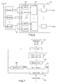
- the figure 1 represents a simplified diagram of an example architecture of a satellite positioning receiver in which only one channel is represented.
- the data contained in each signal received by the satellite positioning receiver 10 is extracted by two successive demodulations carried out by a carrier correlation circuit 20 for the suppression of the carrier of the received signal, followed by a circuit 22.
- the satellite positioning receiver 10 elaborates a local replica PI of the carrier. generated by a local oscillator 24 controlled by a frequency and phase tracking loop, called a phase loop 20, and a local replica of the pseudo-random spreading code generated by a local code generator 28 driven by a tracking loop
- the techniques for tracking the received signal require the development of a local replica of the spreading code, called point replica Cp, and other local replicas in advance Ca and late Cr.
- INT integrators have the role of producing samples of demodulated and despread signal, cumulative, Za advance, punctual Zp, Zr delay.
- the phase loop 20, respectively the code loop 22, comprises a carrier discriminator 21 DSP and DSC code, for measuring, using the values of the signal samples Zp, Za, Zr delivered by the integrator INT at the output of the spot and delay point correlators, the carrier phase differences, respectively the code differences, between the received signal and the local signal, for feedback in the corresponding phase and code tracking loops 20, 22 in order to updating the estimate of the carrier frequency of the received signal, respectively the offset of the spreading code measured with respect to the local code.
- a carrier discriminator 21 DSP and DSC code for measuring, using the values of the signal samples Zp, Za, Zr delivered by the integrator INT at the output of the spot and delay point correlators, the carrier phase differences, respectively the code differences, between the received signal and the local signal, for feedback in the corresponding phase and code tracking loops 20, 22 in order to updating the estimate of the carrier frequency of the received signal, respectively the offset of the spreading code measured with respect to the local code.
- DSP carrier discriminator 21 and DSC code carrier phase deviations are transmitted to a CRP carrier corrector 23 controlling a carrier oscillator 24 generating a carrier local phase driving a carrier generator 26 which provides the carrier local used by the carrier correlation circuit 20 for removing the carrier from the received signal.
- the code gaps are transmitted to a CRC code corrector 25 controlling a code oscillator 28 generating a local code phase driving the code generator 30 which provides local codes Ca, Cp, Cr used by the code correlation circuit 22.
- the output of each discriminator 21 is constrained, by the code tracking loop 22, to deliver a value close to zero to keep the synchronization of the local code on the satellite code.
- Synchronization of local codes is therefore done satellite-by-satellite independently of other satellites.
- the GNSS receiver is used alone, it is very difficult to identify an erroneous navigation signal and the position information obtained is unreliable.
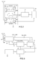
- the receiver 10 can be integrated into a vectorized loop architecture, as represented for example in the diagram of the figure 2 , or in an INS / GNSS hybridization architecture as represented for example in the diagram of the figure 3 .
- the position and speed measurements of the receiver 10 are determined by taking into account error residues of an innovation parameter delivered at the output of a channel filter 11, for example a noise filter. Kalman.
- the channel filter 11 takes into account all the information extracted from the N navigation signals 51, ... 5N received by the receiver 10 to calculate the innovation parameter corresponding to the difference between the measurements reported by the receiver 10 and the prediction of these measurements made by a mathematical model included in the channel filter 11 and deduce an estimate of the offset of the code and carrier clocks of the receiver 10 with respect to the N satellites N having emitted signals 51 to 5N.
- the channel filter 11 takes into account all the information extracted from the N navigation signals 51, ... 5N received by the receiver 10 to calculate the innovation parameter corresponding to the difference between the measurements reported by the receiver 10 and the prediction of these measurements made by a mathematical model included in the channel filter 11 and deduce an estimate of the offset of the code and carrier clocks of the receiver 10 with respect to the N satellites N having emitted signals 51 to 5N.
- the code offset, respectively the carrier offset, delivered at the output of the channel filter 11 is applied at the input of a device 12 for predicting the Doppler effect on the code and the carrier, this Doppler effect being due to the movement of the satellites, the movement of the local oscillator of the receiver and the movement of the receiver 10.
- the device 12 for predicting the Doppler effect outputs new position control values of the code clocks and phase which are applied to the local oscillators 28 of the code loops, respectively to the local oscillators 24 of the phase loops, of the N channels of the receiver 10 in order to update, simultaneously, the code and phase clocks of all the channels from of one and the same code control value 6, respectively of phase 7.
- the start of the local spreading codes used for the correlation is thus triggered simultaneously in all the channels.
- This vectorized loop architecture therefore makes it possible to take into account jointly, a set of information from the discriminators 21 of all the channels of the receiver 10 to simultaneously correct by the same value, at each iteration, the position of the point correlators Cp, advance Ca and delay Cr, in all the reliable channels of the receiver 10.
- the position of the correlators of all the channels is therefore jointly managed by the channel filter 11 and the output signals of the code discriminators 21 and carrier, are not constrained.
- the channel filter 11 In addition to the information extracted from the set of navigation signals by the satellite positioning receiver 10 for calculating the innovation parameter, the channel filter 11 also takes into account position information, speed and acceleration, transmitted by an inertial unit 14 placed on board the vehicle in which the receiver 10 is located. From all the information extracted from the navigation signals 51, ..., 5i, ..., 5N, and information from the inertial unit 14, the channel filter 11 jointly estimates the new position of the point correlators Cp, Ca advance and Cr delay of all the channels, 1 to N, of the receiver 10.
- a navigation calculator 13 connected to the output of the inertial unit 14, receives position information delivered by the inertial unit 14 and position, speed and acceleration error information estimated by the channel filter 11 from the error values DC1, DP1,..., DCi, DPi,..., DCN, DPN, resulting from the discriminators 21 of each channel 1, ... i, ..., N, of the receiver 10.
- the navigation computer 13 delivers new values of position, of speed and attitude of the vehicle in which is located the receiver 10 and the inertial unit 14.
- the new values of position, speed and attitude are applied to the input of a device 12 for predicting the Doppler effect on the code and the carrier which also receives additional information transmitted by the receiver 10 from the signals from the satellites and the code and carrier offsets from the channel filter 11.
- the additional information 8 transmitted by the receiver 10 to the device 12 of prediction of the Doppler effect comprise ephemeris data and a propagation error estimate which make it possible to deduce an approximation of the propagation delay of the signals coming from the satellites. This delay is introduced notably by the ionosphere, the troposphere and the satellite clock.
- the device 12 for predicting the Doppler effect delivers, at the output, new position control values of the code and phase clocks to be applied to all the channels, 1 to N, to simultaneously and jointly correct the same value. , at each iteration, the position of the point correlators Cp, Ca advance and Cr delay in all channels of the receiver 10.
- the position of the correlators of all the channels is managed in common by the channel filter 11 and the output signals of the discriminators 21 of DSC code and DSP carrier are not constrained.
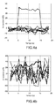
- the Figures 4a and 4b are two examples of curves illustrating the evolution, as a function of time, of the innovation parameters delivered at the output of a Kalman filter of a hybridization architecture of the ultra-tight coupling type, for noisy signals in which the levels of the C / N0 signal-to-noise ratio are 40dBHz and 19dBHz, respectively.
- the signals in fine lines corresponding to direct paths between a satellite and a satellite positioning receiver have an innovation parameter that fluctuates around the zero value, whereas an erroneous signal, represented in thick line, due for example to a multiple path, that is to say to a path that has been reflected by an obstacle between a satellite and the satellite positioning receiver, is not centered around the zero value.
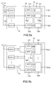
- the Figures 5a and 5b represent two examples of architectures of an anomaly detection system on GNSS navigation signals.
- the anomaly detection system comprises a satellite positioning receiver and an abnormality detecting device.
- the receiver 10 comprises a plurality of different processing channels 1 to N, each processing channel being dedicated to a satellite and comprising a carrier and code discriminator 21 delivering a carrier phase difference and a code difference between the received signal. of the corresponding satellite and the local signal.
- the code and carrier discriminators 21 of the receiver 10 are not constrained to a close output value. of zero and their variations are therefore representative of the fluctuations of the signals received by the receiver 10.
- the anomaly detecting device 15 comprises a comparison device 16 including a first threshold value S1 and connected at the output of all the discriminators 21, and a measurement error identification device 18 connected to the output of the device of FIG. comparison 16.
- the comparison device 16 comprises a first set of N comparators 161, 162, ... 16N corresponding to the N channels 1 to N.
- the first set of N comparators 161 to 16N is intended to receive all the values of code deviation DCi, where i is an integer between 1 and N, delivered by the discriminators 21 of all the channels 1 to N of the receiver 10, to compare the code deviation values delivered by each discriminator 21 to the same first threshold value S1 and to deliver the results of the comparison on a plurality of outputs each corresponding to one of the reception channels 1 to N of the receiver 10.
- the first threshold value S1 is defined p
- the user identification device is a maximum code gap value that the user is ready to accept at the output of the discriminators 21.
- the measurement error identification device 18 has N error identification channels 181. , 182, ... 18N connected at the output of the first set of N comparators161 to 16N.
- the measurement error identification device 18 is intended, from the results ⁇ DCi, where i is between 1 and N, of each comparison, to assign a confidence indicator IC1, IC2, ... ICN on the reliability of each received signal 51, 52, ... 5N and identifying the erroneous navigation signals, i.e. the signals corresponding to a low confidence indicator lower than a minimum confidence indicator ICmin.
- the comparator 16 may further comprise a second set of N comparators 171, at 17N including a second threshold value S2 and connected at the output of all the discriminators 21.
- comparison 16 can then furthermore compare the phase difference values DPi, where i is between 1 and N, delivered by each discriminator 21 to said same second threshold value S2 and the error identification device 18 can from the results of each comparison, determine the phase differences DPi greater than the second threshold value S2.
- the confidence indicator IC1 to ICN assigned to each received signal is determined by taking into account the results ⁇ DCi and ⁇ DPi, where i is between 1 and N, comparisons coming from, on the one hand, DCi code differences. and secondly phase differences DPi with respect to the first, respectively to the second, threshold value S1, S2.
- the anomaly detection device 15 can be used to obtain only information on the reliability of the position measurements reported by the receiver 10. In this case, the calculation of the innovation parameter is unchanged and determined by the channel filter 11 from of all GNSS navigation signals.
- the anomaly detection device 15 can also be used to exclude the erroneous signals upstream of the channel filter 11 and to produce, in the channel filter 11, an innovation calculation only from the DCi code error values and the carrier phase error values DPi of the estimated reliable signals.
- the position of the correlators is then determined with greater precision than in the prior art where all the signals, including the erroneous signals, are used in the channel filter 11 to calculate the innovation parameter, and where the erroneous signals are more difficult to detect.
- the abnormality detection device 15 further comprises an additional device, called a selection device 19, comprising a plurality inputs connected to the different outputs of the error identification device 18 and a plurality of outputs for connection to the channel filter 11.
- the selection device 19 is for selecting signals having a confidence indicator greater than one. predetermined minimum confidence indicator ICmin below which a navigation signal is estimated to be erroneous and to transmit only the selected signals to the channel 11 filter of the vectorized loop architecture or the INS / GNSS architecture.
- the calculation of the innovation parameter in the channel filter 11 is then carried out, in the case of the vectorized loop architecture, taking into account only the set of information extracted from the GNSS navigation signals that has been estimated as reliable and, in the case of the INS / GNSS hybridization architecture, taking into account only the information extracted from the GNSS signals that has been estimated as reliable and information from the inertial unit 14.
- the figure 7 is an example of an algorithm for anomaly detection and selection of reliable GNSS signals.
- a first initialization step 70 the first and second threshold values S1 and S2 and the value of the minimum confidence indicator ICmin are chosen.
- the code deviation values DCi and DPi delivered at the output of the discriminators 21 of each channel i of the GNSS receiver 10, where i is an integer between 1 and N, are respectively compared with the first and second threshold values S1 and S2, the results of each comparison being denoted ⁇ DCi, respectively ⁇ DPi.
- a confidence indicator IC1, IC2, ... ICN on the reliability of each received signal 51, 52, ...
- a comparison test is performed between each confidence indicator ICi assigned to each channel i and the minimum confidence indicator ICmin.
- the signal is identified as reliable in the step 74 and selected to be transmitted to the channel filter 11 in step 75, when the anomaly detection system is integrated in a vectorized loop architecture or in a hybridization architecture. In the opposite case, the signal is identified as erroneous in step 76 and is not transmitted to the channel filter 11.
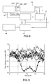
- the figure 8 represents an exemplary hybridization architecture including a device for detecting anomaly and selecting reliable GNSS signals, according to the invention.
- This architecture comprises the same devices and the same structure as the architecture represented on the figure 3 and further comprises a device for detecting anomaly and selection of reliable GNSS signals connected between the receiver 10 and the channel filter 11.
- the device 15 for anomaly detection and selection of reliable GNSS signals extracts the values d code error DC1 to DCN and the carrier phase error values DP1 to DPN output from the discriminators 21 of the GNSS receiver 10, compares them with the first and second respective threshold values S1, S2, derives an indicator of Confidence IC1 to ICN and selects and transmits only the code error values DC1 to DCN and the carrier phase error values DP1 to DPN of the signals estimated to be reliable at the channel filter 11.
- the figure 9 represents an example of a curve illustrating the evolution, as a function of time, of the outputs of the code discriminators of a satellite positioning receiver 10, the receiver 10 being integrated into an ultra-tight coupling hybridization architecture, for noisy signals in which the level of the signal-to-noise ratio C / N0 is equal to 19dBHz.
- the correlators are controlled together from a joint estimate of their code offset, so that the discriminators output error signals that are not constrained to a value close to zero.
- This figure 9 shows that even when the noise level is high relative to the signal level, the erroneous signals outputted from the code discriminators of each channel are very clearly distinguished from the reliable signals and can easily be detected by comparing them to a threshold.
- the threshold is chosen according to the desired application. The threshold may for example correspond to a false alarm probability or a desired position and speed measurement accuracy.
- a threshold of -20 dB allows the signal shown in thick lines to be detected and corresponding to an erroneous signal.
Landscapes
- Engineering & Computer Science (AREA)
- Radar, Positioning & Navigation (AREA)
- Remote Sensing (AREA)
- Computer Networks & Wireless Communication (AREA)
- Physics & Mathematics (AREA)
- General Physics & Mathematics (AREA)
- Computer Security & Cryptography (AREA)
- Position Fixing By Use Of Radio Waves (AREA)
Applications Claiming Priority (1)
| Application Number | Priority Date | Filing Date | Title |
|---|---|---|---|
| FR1203406A FR2999727B1 (fr) | 2012-12-14 | 2012-12-14 | Procede et systeme de detection d'anomalie sur des signaux de navigation par satellites et systeme d'hybridation comportant un tel systeme de detection |
Publications (2)
| Publication Number | Publication Date |
|---|---|
| EP2743729A1 true EP2743729A1 (de) | 2014-06-18 |
| EP2743729B1 EP2743729B1 (de) | 2022-07-13 |
Family
ID=48692522
Family Applications (1)
| Application Number | Title | Priority Date | Filing Date |
|---|---|---|---|
| EP13196515.4A Active EP2743729B1 (de) | 2012-12-14 | 2013-12-10 | Verfahren und System zur Erkennung von Anomalien bei satellitenübertragenen Navigationssignalen, und Hybridsystem, das ein solches Erkennungssystem umfasst |
Country Status (6)
| Country | Link |
|---|---|
| US (1) | US9612336B2 (de) |
| EP (1) | EP2743729B1 (de) |
| JP (1) | JP6479314B2 (de) |
| ES (1) | ES2926525T3 (de) |
| FR (1) | FR2999727B1 (de) |
| SG (1) | SG2013093570A (de) |
Cited By (1)
| Publication number | Priority date | Publication date | Assignee | Title |
|---|---|---|---|---|
| CN116009031A (zh) * | 2022-12-19 | 2023-04-25 | 中国人民解放军国防科技大学 | 一种面向紧组合导航系统的隐蔽性欺骗方法 |
Families Citing this family (5)
| Publication number | Priority date | Publication date | Assignee | Title |
|---|---|---|---|---|
| FR3021147B1 (fr) * | 2014-05-16 | 2017-12-22 | Thales Sa | Dispositif de controle des donnees portees par un equipement embarque, systeme de collecte de taxe et procede associes |
| US11808865B2 (en) | 2016-03-24 | 2023-11-07 | Focal Point Positioning Limited | Method and system for calibrating a system parameter |
| CN107479069A (zh) * | 2017-08-01 | 2017-12-15 | 天津博创金成技术开发有限公司 | 一种慢变斜坡故障完好性监测方法 |
| CN111443363B (zh) * | 2020-01-17 | 2023-07-04 | 中国人民解放军战略支援部队信息工程大学 | 一种卫星导航的欺骗识别方法及装置 |
| US20220391796A1 (en) * | 2020-08-12 | 2022-12-08 | Everseen Limited | System and Method for Mapping Risks in a Warehouse Environment |
Citations (3)
| Publication number | Priority date | Publication date | Assignee | Title |
|---|---|---|---|---|
| US6198765B1 (en) * | 1996-04-25 | 2001-03-06 | Sirf Technologies, Inc. | Spread spectrum receiver with multi-path correction |
| WO2004031797A1 (en) * | 2002-09-24 | 2004-04-15 | Honeywell International Inc. | Radio frequency interference monitor |
| US20050114023A1 (en) * | 2003-11-26 | 2005-05-26 | Williamson Walton R. | Fault-tolerant system, apparatus and method |
Family Cites Families (5)
| Publication number | Priority date | Publication date | Assignee | Title |
|---|---|---|---|---|
| WO2007098787A1 (en) * | 2006-03-03 | 2007-09-07 | Agence Spatiale Europeenne | Method of processing positioning signals, in particular for indoor applications. |
| US8027413B2 (en) * | 2007-07-11 | 2011-09-27 | The Aerospace Corporation | Ultratight coupling prefilter detection block |
| FR2942325B1 (fr) * | 2009-02-19 | 2011-03-04 | Thales Sa | Procede de lever d'ambiguite, procede de localisation d'un recepteur par radionavigation comprenant une etape de lever d'ambiguite et recepteur de localisation |
| EP2463685B1 (de) * | 2010-12-07 | 2017-08-02 | Airbus DS GmbH | Verfahren zur Synchronisierung eines Empfängers mit empfangenem unklaren Signal mit einer bekannten Anzahl von mindestens zwei Spitzenwerten |
| JP2012145342A (ja) * | 2011-01-07 | 2012-08-02 | Furuno Electric Co Ltd | メッセージデータ受信方法、メッセージデータ受信プログラム、メッセージデータ受信装置、gnss信号受信方法、gnss信号受信プログラム、gnss信号受信装置、および移動端末 |
-
2012
- 2012-12-14 FR FR1203406A patent/FR2999727B1/fr not_active Expired - Fee Related
-
2013
- 2013-12-10 ES ES13196515T patent/ES2926525T3/es active Active
- 2013-12-10 EP EP13196515.4A patent/EP2743729B1/de active Active
- 2013-12-13 US US14/106,486 patent/US9612336B2/en active Active
- 2013-12-16 SG SG2013093570A patent/SG2013093570A/en unknown
- 2013-12-16 JP JP2013259316A patent/JP6479314B2/ja active Active
Patent Citations (3)
| Publication number | Priority date | Publication date | Assignee | Title |
|---|---|---|---|---|
| US6198765B1 (en) * | 1996-04-25 | 2001-03-06 | Sirf Technologies, Inc. | Spread spectrum receiver with multi-path correction |
| WO2004031797A1 (en) * | 2002-09-24 | 2004-04-15 | Honeywell International Inc. | Radio frequency interference monitor |
| US20050114023A1 (en) * | 2003-11-26 | 2005-05-26 | Williamson Walton R. | Fault-tolerant system, apparatus and method |
Cited By (1)
| Publication number | Priority date | Publication date | Assignee | Title |
|---|---|---|---|---|
| CN116009031A (zh) * | 2022-12-19 | 2023-04-25 | 中国人民解放军国防科技大学 | 一种面向紧组合导航系统的隐蔽性欺骗方法 |
Also Published As
| Publication number | Publication date |
|---|---|
| ES2926525T3 (es) | 2022-10-26 |
| JP6479314B2 (ja) | 2019-03-06 |
| FR2999727B1 (fr) | 2014-12-19 |
| FR2999727A1 (fr) | 2014-06-20 |
| SG2013093570A (en) | 2014-07-30 |
| JP2014119459A (ja) | 2014-06-30 |
| EP2743729B1 (de) | 2022-07-13 |
| US9612336B2 (en) | 2017-04-04 |
| US20140313077A1 (en) | 2014-10-23 |
Similar Documents
| Publication | Publication Date | Title |
|---|---|---|
| FR3076354B1 (fr) | Procede de controle de l'integralite de l'estimation de la position d'un porteur mobile dans un systeme de mesure de positionnement par satellite | |
| EP2743729B1 (de) | Verfahren und System zur Erkennung von Anomalien bei satellitenübertragenen Navigationssignalen, und Hybridsystem, das ein solches Erkennungssystem umfasst | |
| EP2998765B1 (de) | System zum ausschluss eines ausfalls eines satelliten in einem gnss-system | |
| EP2987036A1 (de) | Integritätssteuerungsverfahren und fusions-/konsolidierungsvorrichtung mit mehreren verarbeitungsmodulen | |
| FR3025610A1 (fr) | Procede de determination collaborative d'erreurs de positionnement d'un systeme de navigation par satellites | |
| EP2449409A1 (de) | Verfahren zur bestimmung der position eines mobilen körpers in einem bestimmten moment und zur überwachung der integrität der position des mobilen körpers | |
| FR2936669A1 (fr) | Procede pour optimiser une acquisition d'un signal a spectre etale provenant d'un satellite par un recepteur mobile | |
| CN113093237B (zh) | Ssr轨钟改正数质量因子实时评估方法、装置、设备及介质 | |
| EP2500750A1 (de) | Verfahren und Vorrichtung zur Eichung eines Empfängers | |
| FR2942325A1 (fr) | Procede de lever d'ambiguite, procede de localisation d'un recepteur par radionavigation comprenant une etape de lever d'ambiguite et recepteur de localisation | |
| EP3353573A1 (de) | Verfahren und system zur bahnpositionierung | |
| FR3020687A1 (fr) | Procede de determination de la position d'un recepteur de systeme de navigation par satellites, et systeme associe | |
| EP3405813B1 (de) | Satellitennavigationsvorrichtung und verfahren zur steuerung davon | |
| EP4307010A1 (de) | Mac-überwachungsverfahren mit gemeinsamer kompensation der integrität eines punktpositionierungsverfahrens durch virtuelle baken | |
| FR2888942A1 (fr) | Procede, dispositif et systeme de positionnement par relais pulse multi synchrone multi sources | |
| EP1907876B1 (de) | Mobilgeräte, verfahren und system zur positionsbestimmung eines mobilgeräts | |
| FR3100066A1 (fr) | Detection d'une operation de leurrage d'un recepteur de signaux satellitaires | |
| FR3166710A1 (fr) | Méthode de localisation d’un nœud mobile assisté par un modèle d’intelligence artificielle et une carte de visibilité | |
| EP4443197A1 (de) | Integritätssteuerungsverfahren, computerprogramm und vorrichtung dafür | |
| FR3138513A1 (fr) | Filtrage adapté à coïncidence d’angles pour détection de passage embarquée d’un mobile se déplaçant sur une trajectoire contrainte | |
| EP4585957A1 (de) | Winkelangepasste filterung zur on-board-erkennung eines mobilen gerätes, das sich auf einer eingeschränkten trajektorie bewegt | |
| EP4232849A1 (de) | Verfahren zur erkennung der maskierung eines oder mehrerer satelliten, elektronische detektionsvorrichtung und zugehöriges computerprogrammprodukt | |
| FR3140447A1 (fr) | Procédé de contrôle de l’intégrité d’une pluralité de mesures de pseudo-distances acquises par un système de navigation |
Legal Events
| Date | Code | Title | Description |
|---|---|---|---|
| PUAI | Public reference made under article 153(3) epc to a published international application that has entered the european phase |
Free format text: ORIGINAL CODE: 0009012 |
|
| 17P | Request for examination filed |
Effective date: 20131210 |
|
| AK | Designated contracting states |
Kind code of ref document: A1 Designated state(s): AL AT BE BG CH CY CZ DE DK EE ES FI FR GB GR HR HU IE IS IT LI LT LU LV MC MK MT NL NO PL PT RO RS SE SI SK SM TR |
|
| AX | Request for extension of the european patent |
Extension state: BA ME |
|
| R17P | Request for examination filed (corrected) |
Effective date: 20141106 |
|
| RBV | Designated contracting states (corrected) |
Designated state(s): AL AT BE BG CH CY CZ DE DK EE ES FI FR GB GR HR HU IE IS IT LI LT LU LV MC MK MT NL NO PL PT RO RS SE SI SK SM TR |
|
| STAA | Information on the status of an ep patent application or granted ep patent |
Free format text: STATUS: EXAMINATION IS IN PROGRESS |
|
| 17Q | First examination report despatched |
Effective date: 20170929 |
|
| REG | Reference to a national code |
Ref country code: DE Ref legal event code: R079 Ref document number: 602013082057 Country of ref document: DE Free format text: PREVIOUS MAIN CLASS: G01S0019200000 Ipc: G01S0019220000 |
|
| RIC1 | Information provided on ipc code assigned before grant |
Ipc: G01S 19/22 20100101AFI20211223BHEP |
|
| GRAP | Despatch of communication of intention to grant a patent |
Free format text: ORIGINAL CODE: EPIDOSNIGR1 |
|
| STAA | Information on the status of an ep patent application or granted ep patent |
Free format text: STATUS: GRANT OF PATENT IS INTENDED |
|
| INTG | Intention to grant announced |
Effective date: 20220208 |
|
| GRAS | Grant fee paid |
Free format text: ORIGINAL CODE: EPIDOSNIGR3 |
|
| GRAA | (expected) grant |
Free format text: ORIGINAL CODE: 0009210 |
|
| STAA | Information on the status of an ep patent application or granted ep patent |
Free format text: STATUS: THE PATENT HAS BEEN GRANTED |
|
| AK | Designated contracting states |
Kind code of ref document: B1 Designated state(s): AL AT BE BG CH CY CZ DE DK EE ES FI FR GB GR HR HU IE IS IT LI LT LU LV MC MK MT NL NO PL PT RO RS SE SI SK SM TR |
|
| RAP3 | Party data changed (applicant data changed or rights of an application transferred) |
Owner name: THALES |
|
| REG | Reference to a national code |
Ref country code: GB Ref legal event code: FG4D Free format text: NOT ENGLISH |
|
| REG | Reference to a national code |
Ref country code: CH Ref legal event code: EP |
|
| REG | Reference to a national code |
Ref country code: IE Ref legal event code: FG4D Free format text: LANGUAGE OF EP DOCUMENT: FRENCH |
|
| REG | Reference to a national code |
Ref country code: DE Ref legal event code: R096 Ref document number: 602013082057 Country of ref document: DE |
|
| REG | Reference to a national code |
Ref country code: AT Ref legal event code: REF Ref document number: 1504554 Country of ref document: AT Kind code of ref document: T Effective date: 20220815 |
|
| REG | Reference to a national code |
Ref country code: ES Ref legal event code: FG2A Ref document number: 2926525 Country of ref document: ES Kind code of ref document: T3 Effective date: 20221026 |
|
| REG | Reference to a national code |
Ref country code: LT Ref legal event code: MG9D |
|
| REG | Reference to a national code |
Ref country code: NL Ref legal event code: MP Effective date: 20220713 |
|
| PG25 | Lapsed in a contracting state [announced via postgrant information from national office to epo] |
Ref country code: SE Free format text: LAPSE BECAUSE OF FAILURE TO SUBMIT A TRANSLATION OF THE DESCRIPTION OR TO PAY THE FEE WITHIN THE PRESCRIBED TIME-LIMIT Effective date: 20220713 Ref country code: RS Free format text: LAPSE BECAUSE OF FAILURE TO SUBMIT A TRANSLATION OF THE DESCRIPTION OR TO PAY THE FEE WITHIN THE PRESCRIBED TIME-LIMIT Effective date: 20220713 Ref country code: PT Free format text: LAPSE BECAUSE OF FAILURE TO SUBMIT A TRANSLATION OF THE DESCRIPTION OR TO PAY THE FEE WITHIN THE PRESCRIBED TIME-LIMIT Effective date: 20221114 Ref country code: NO Free format text: LAPSE BECAUSE OF FAILURE TO SUBMIT A TRANSLATION OF THE DESCRIPTION OR TO PAY THE FEE WITHIN THE PRESCRIBED TIME-LIMIT Effective date: 20221013 Ref country code: NL Free format text: LAPSE BECAUSE OF FAILURE TO SUBMIT A TRANSLATION OF THE DESCRIPTION OR TO PAY THE FEE WITHIN THE PRESCRIBED TIME-LIMIT Effective date: 20220713 Ref country code: LV Free format text: LAPSE BECAUSE OF FAILURE TO SUBMIT A TRANSLATION OF THE DESCRIPTION OR TO PAY THE FEE WITHIN THE PRESCRIBED TIME-LIMIT Effective date: 20220713 Ref country code: LT Free format text: LAPSE BECAUSE OF FAILURE TO SUBMIT A TRANSLATION OF THE DESCRIPTION OR TO PAY THE FEE WITHIN THE PRESCRIBED TIME-LIMIT Effective date: 20220713 Ref country code: FI Free format text: LAPSE BECAUSE OF FAILURE TO SUBMIT A TRANSLATION OF THE DESCRIPTION OR TO PAY THE FEE WITHIN THE PRESCRIBED TIME-LIMIT Effective date: 20220713 |
|
| REG | Reference to a national code |
Ref country code: AT Ref legal event code: MK05 Ref document number: 1504554 Country of ref document: AT Kind code of ref document: T Effective date: 20220713 |
|
| PG25 | Lapsed in a contracting state [announced via postgrant information from national office to epo] |
Ref country code: PL Free format text: LAPSE BECAUSE OF FAILURE TO SUBMIT A TRANSLATION OF THE DESCRIPTION OR TO PAY THE FEE WITHIN THE PRESCRIBED TIME-LIMIT Effective date: 20220713 Ref country code: IS Free format text: LAPSE BECAUSE OF FAILURE TO SUBMIT A TRANSLATION OF THE DESCRIPTION OR TO PAY THE FEE WITHIN THE PRESCRIBED TIME-LIMIT Effective date: 20221113 Ref country code: HR Free format text: LAPSE BECAUSE OF FAILURE TO SUBMIT A TRANSLATION OF THE DESCRIPTION OR TO PAY THE FEE WITHIN THE PRESCRIBED TIME-LIMIT Effective date: 20220713 Ref country code: GR Free format text: LAPSE BECAUSE OF FAILURE TO SUBMIT A TRANSLATION OF THE DESCRIPTION OR TO PAY THE FEE WITHIN THE PRESCRIBED TIME-LIMIT Effective date: 20221014 |
|
| REG | Reference to a national code |
Ref country code: DE Ref legal event code: R097 Ref document number: 602013082057 Country of ref document: DE |
|
| PG25 | Lapsed in a contracting state [announced via postgrant information from national office to epo] |
Ref country code: SM Free format text: LAPSE BECAUSE OF FAILURE TO SUBMIT A TRANSLATION OF THE DESCRIPTION OR TO PAY THE FEE WITHIN THE PRESCRIBED TIME-LIMIT Effective date: 20220713 Ref country code: RO Free format text: LAPSE BECAUSE OF FAILURE TO SUBMIT A TRANSLATION OF THE DESCRIPTION OR TO PAY THE FEE WITHIN THE PRESCRIBED TIME-LIMIT Effective date: 20220713 Ref country code: DK Free format text: LAPSE BECAUSE OF FAILURE TO SUBMIT A TRANSLATION OF THE DESCRIPTION OR TO PAY THE FEE WITHIN THE PRESCRIBED TIME-LIMIT Effective date: 20220713 Ref country code: CZ Free format text: LAPSE BECAUSE OF FAILURE TO SUBMIT A TRANSLATION OF THE DESCRIPTION OR TO PAY THE FEE WITHIN THE PRESCRIBED TIME-LIMIT Effective date: 20220713 Ref country code: AT Free format text: LAPSE BECAUSE OF FAILURE TO SUBMIT A TRANSLATION OF THE DESCRIPTION OR TO PAY THE FEE WITHIN THE PRESCRIBED TIME-LIMIT Effective date: 20220713 |
|
| PLBE | No opposition filed within time limit |
Free format text: ORIGINAL CODE: 0009261 |
|
| STAA | Information on the status of an ep patent application or granted ep patent |
Free format text: STATUS: NO OPPOSITION FILED WITHIN TIME LIMIT |
|
| PG25 | Lapsed in a contracting state [announced via postgrant information from national office to epo] |
Ref country code: SK Free format text: LAPSE BECAUSE OF FAILURE TO SUBMIT A TRANSLATION OF THE DESCRIPTION OR TO PAY THE FEE WITHIN THE PRESCRIBED TIME-LIMIT Effective date: 20220713 Ref country code: EE Free format text: LAPSE BECAUSE OF FAILURE TO SUBMIT A TRANSLATION OF THE DESCRIPTION OR TO PAY THE FEE WITHIN THE PRESCRIBED TIME-LIMIT Effective date: 20220713 |
|
| 26N | No opposition filed |
Effective date: 20230414 |
|
| PG25 | Lapsed in a contracting state [announced via postgrant information from national office to epo] |
Ref country code: AL Free format text: LAPSE BECAUSE OF FAILURE TO SUBMIT A TRANSLATION OF THE DESCRIPTION OR TO PAY THE FEE WITHIN THE PRESCRIBED TIME-LIMIT Effective date: 20220713 |
|
| GBPC | Gb: european patent ceased through non-payment of renewal fee |
Effective date: 20221210 |
|
| REG | Reference to a national code |
Ref country code: BE Ref legal event code: MM Effective date: 20221231 |
|
| PG25 | Lapsed in a contracting state [announced via postgrant information from national office to epo] |
Ref country code: SI Free format text: LAPSE BECAUSE OF FAILURE TO SUBMIT A TRANSLATION OF THE DESCRIPTION OR TO PAY THE FEE WITHIN THE PRESCRIBED TIME-LIMIT Effective date: 20220713 Ref country code: LU Free format text: LAPSE BECAUSE OF NON-PAYMENT OF DUE FEES Effective date: 20221210 |
|
| PG25 | Lapsed in a contracting state [announced via postgrant information from national office to epo] |
Ref country code: IE Free format text: LAPSE BECAUSE OF NON-PAYMENT OF DUE FEES Effective date: 20221210 Ref country code: GB Free format text: LAPSE BECAUSE OF NON-PAYMENT OF DUE FEES Effective date: 20221210 |
|
| PG25 | Lapsed in a contracting state [announced via postgrant information from national office to epo] |
Ref country code: BE Free format text: LAPSE BECAUSE OF NON-PAYMENT OF DUE FEES Effective date: 20221231 |
|
| PG25 | Lapsed in a contracting state [announced via postgrant information from national office to epo] |
Ref country code: HU Free format text: LAPSE BECAUSE OF FAILURE TO SUBMIT A TRANSLATION OF THE DESCRIPTION OR TO PAY THE FEE WITHIN THE PRESCRIBED TIME-LIMIT; INVALID AB INITIO Effective date: 20131210 |
|
| PG25 | Lapsed in a contracting state [announced via postgrant information from national office to epo] |
Ref country code: CY Free format text: LAPSE BECAUSE OF FAILURE TO SUBMIT A TRANSLATION OF THE DESCRIPTION OR TO PAY THE FEE WITHIN THE PRESCRIBED TIME-LIMIT Effective date: 20220713 |
|
| PG25 | Lapsed in a contracting state [announced via postgrant information from national office to epo] |
Ref country code: MK Free format text: LAPSE BECAUSE OF FAILURE TO SUBMIT A TRANSLATION OF THE DESCRIPTION OR TO PAY THE FEE WITHIN THE PRESCRIBED TIME-LIMIT Effective date: 20220713 |
|
| PG25 | Lapsed in a contracting state [announced via postgrant information from national office to epo] |
Ref country code: MC Free format text: LAPSE BECAUSE OF FAILURE TO SUBMIT A TRANSLATION OF THE DESCRIPTION OR TO PAY THE FEE WITHIN THE PRESCRIBED TIME-LIMIT Effective date: 20220713 |
|
| PG25 | Lapsed in a contracting state [announced via postgrant information from national office to epo] |
Ref country code: TR Free format text: LAPSE BECAUSE OF FAILURE TO SUBMIT A TRANSLATION OF THE DESCRIPTION OR TO PAY THE FEE WITHIN THE PRESCRIBED TIME-LIMIT Effective date: 20220713 Ref country code: MC Free format text: LAPSE BECAUSE OF FAILURE TO SUBMIT A TRANSLATION OF THE DESCRIPTION OR TO PAY THE FEE WITHIN THE PRESCRIBED TIME-LIMIT Effective date: 20220713 |
|
| PG25 | Lapsed in a contracting state [announced via postgrant information from national office to epo] |
Ref country code: BG Free format text: LAPSE BECAUSE OF FAILURE TO SUBMIT A TRANSLATION OF THE DESCRIPTION OR TO PAY THE FEE WITHIN THE PRESCRIBED TIME-LIMIT Effective date: 20220713 |
|
| PG25 | Lapsed in a contracting state [announced via postgrant information from national office to epo] |
Ref country code: MT Free format text: LAPSE BECAUSE OF FAILURE TO SUBMIT A TRANSLATION OF THE DESCRIPTION OR TO PAY THE FEE WITHIN THE PRESCRIBED TIME-LIMIT Effective date: 20220713 |
|
| REG | Reference to a national code |
Ref country code: CH Ref legal event code: U11 Free format text: ST27 STATUS EVENT CODE: U-0-0-U10-U11 (AS PROVIDED BY THE NATIONAL OFFICE) Effective date: 20260101 |
|
| PGFP | Annual fee paid to national office [announced via postgrant information from national office to epo] |
Ref country code: DE Payment date: 20251119 Year of fee payment: 13 |
|
| PGFP | Annual fee paid to national office [announced via postgrant information from national office to epo] |
Ref country code: IT Payment date: 20251126 Year of fee payment: 13 |
|
| PGFP | Annual fee paid to national office [announced via postgrant information from national office to epo] |
Ref country code: FR Payment date: 20251124 Year of fee payment: 13 |
|
| PGFP | Annual fee paid to national office [announced via postgrant information from national office to epo] |
Ref country code: ES Payment date: 20260113 Year of fee payment: 13 |
|
| PGFP | Annual fee paid to national office [announced via postgrant information from national office to epo] |
Ref country code: CH Payment date: 20260101 Year of fee payment: 13 |