EP2743734A2 - Compartimentage 4D orientée cible dans un point de réflexion commun - Google Patents
Compartimentage 4D orientée cible dans un point de réflexion commun Download PDFInfo
- Publication number
- EP2743734A2 EP2743734A2 EP13197535.1A EP13197535A EP2743734A2 EP 2743734 A2 EP2743734 A2 EP 2743734A2 EP 13197535 A EP13197535 A EP 13197535A EP 2743734 A2 EP2743734 A2 EP 2743734A2
- Authority
- EP
- European Patent Office
- Prior art keywords
- seismic
- traces
- reflection
- component
- target
- Prior art date
- Legal status (The legal status is an assumption and is not a legal conclusion. Google has not performed a legal analysis and makes no representation as to the accuracy of the status listed.)
- Withdrawn
Links
- 238000000034 method Methods 0.000 claims abstract description 60
- 238000013507 mapping Methods 0.000 claims description 6
- 230000006870 function Effects 0.000 claims description 4
- 238000012545 processing Methods 0.000 abstract description 21
- 230000008569 process Effects 0.000 description 10
- 230000006854 communication Effects 0.000 description 8
- 238000004891 communication Methods 0.000 description 8
- 229930195733 hydrocarbon Natural products 0.000 description 6
- 150000002430 hydrocarbons Chemical class 0.000 description 6
- 239000004215 Carbon black (E152) Substances 0.000 description 5
- 238000012937 correction Methods 0.000 description 4
- 230000005055 memory storage Effects 0.000 description 4
- 238000003491 array Methods 0.000 description 3
- 238000013500 data storage Methods 0.000 description 3
- XLYOFNOQVPJJNP-UHFFFAOYSA-N water Substances O XLYOFNOQVPJJNP-UHFFFAOYSA-N 0.000 description 3
- 230000007175 bidirectional communication Effects 0.000 description 2
- 238000004364 calculation method Methods 0.000 description 2
- 230000002708 enhancing effect Effects 0.000 description 2
- 230000007246 mechanism Effects 0.000 description 2
- 230000000007 visual effect Effects 0.000 description 2
- 241001028048 Nicola Species 0.000 description 1
- 238000004590 computer program Methods 0.000 description 1
- 238000009795 derivation Methods 0.000 description 1
- 238000013461 design Methods 0.000 description 1
- 238000001514 detection method Methods 0.000 description 1
- 238000011161 development Methods 0.000 description 1
- 230000005284 excitation Effects 0.000 description 1
- 238000000605 extraction Methods 0.000 description 1
- 238000005286 illumination Methods 0.000 description 1
- 230000006872 improvement Effects 0.000 description 1
- 230000002452 interceptive effect Effects 0.000 description 1
- 239000004973 liquid crystal related substance Substances 0.000 description 1
- 238000012986 modification Methods 0.000 description 1
- 230000004048 modification Effects 0.000 description 1
- 238000012544 monitoring process Methods 0.000 description 1
- 230000003287 optical effect Effects 0.000 description 1
- 230000037361 pathway Effects 0.000 description 1
- 239000011435 rock Substances 0.000 description 1
- 238000005070 sampling Methods 0.000 description 1
- 239000013049 sediment Substances 0.000 description 1
- 239000007787 solid Substances 0.000 description 1
- 238000012546 transfer Methods 0.000 description 1
Images






Classifications
-
- G—PHYSICS
- G01—MEASURING; TESTING
- G01V—GEOPHYSICS; GRAVITATIONAL MEASUREMENTS; DETECTING MASSES OR OBJECTS; TAGS
- G01V1/00—Seismology; Seismic or acoustic prospecting or detecting
- G01V1/28—Processing seismic data, e.g. for interpretation or for event detection
-
- G—PHYSICS
- G01—MEASURING; TESTING
- G01V—GEOPHYSICS; GRAVITATIONAL MEASUREMENTS; DETECTING MASSES OR OBJECTS; TAGS
- G01V1/00—Seismology; Seismic or acoustic prospecting or detecting
- G01V1/28—Processing seismic data, e.g. for interpretation or for event detection
- G01V1/30—Analysis
- G01V1/308—Time lapse or 4D effects, e.g. production related effects to the formation
-
- G—PHYSICS
- G01—MEASURING; TESTING
- G01V—GEOPHYSICS; GRAVITATIONAL MEASUREMENTS; DETECTING MASSES OR OBJECTS; TAGS
- G01V2210/00—Details of seismic processing or analysis
- G01V2210/60—Analysis
- G01V2210/61—Analysis by combining or comparing a seismic data set with other data
- G01V2210/612—Previously recorded data, e.g. time-lapse or 4D
Definitions
- Embodiments of the subject matter disclosed herein generally relate to methods and systems for seismic data processing and, more particularly, to mechanisms and techniques to preserve specular reflections on a depth target and enhance a 4D target signature.
- Seismic data acquisition and processing techniques are used to generate a profile (image) of a geophysical structure (an horizon) of the strata underlying the land surface or seafloor (the earth subsurface).
- seismic data acquisition involves the generation of acoustic waves and the collection of reflected/refracted versions of those acoustic waves to generate the image.
- This image does not necessarily provide an accurate location for oil and gas reservoirs, but it may suggest, to those trained in the field, the presence or absence of oil and/or gas reservoirs.
- providing an improved image of the subsurface in a shorter period of time is an ongoing process in the field of seismic surveying.
- 4D seismic surveying refers to the technique of taking one seismic survey of a particular geographical area at a first time (i.e., the baseline survey) and another seismic survey of the same geographical area at a later time (i.e., the monitor survey). The baseline survey and the monitor survey can then be compared for various purposes, e.g., to observe changes in the hydrocarbon deposits in a geographical area which has an active well operating therein. Different seismic surveys performed at different times for the same geographical area are also sometimes referred to as different "vintages".
- the surveys be performed in a manner which is highly repeatable, i.e., such that the monitor survey is performed in much the same way (e.g., position of sources and receivers relative to the geography) as the baseline survey was performed.
- 4D binning is a selection process in which the best matching subsets of traces within the full datasets acquired are identified.
- each "trace” refers to the seismic data recorded for one channel, i.e., between a source and a receiver.
- an "offset” refers to a distance relative to template of source and receiver lines used to perform the seismic acquisition. Offsets can be defined in various types or classes. For example, near offsets, mid offsets and far offsets are different classes of offsets which represent different (and increasing) distances from a shot point relative to the acquisition template. Additionally, a "mid-point bin” refers to a square or rectangular area which contains all of the midpoints that correspond to the same common midpoint.
- Fitting associated with selecting the best-fitting pair is calculated from various criteria, e.g., minimal source and receiver positioning misfit and minimal time-window normalized root mean square (NRMS) error between seismic traces.
- NRMS error criterion refers to the RMS value of the difference between two input traces, normalized by the RMS values of the two input traces.
- geological horizons in the vicinity of expected 4D changes, i.e., differences between the monitor survey and the baseline survey which are expected due to, e.g., the extraction of hydrocarbons.
- Selected target horizons such as a reservoir horizon
- dips in this context refer to subsurface reflecting layers which have interfaces which are not perfectly horizontal. Then, with such media features, the midpoint is no longer the reflection point. Consequently, conventional 4D binning could select a couple of traces containing useless diffraction on target traces and discard the specular traces (obeying Snell-Descartes law of reflection) that carry the most important reflective information.
- target-oriented, 4D binning techniques and systems which enable selection of well matched base survey and monitor survey data subsets from the full datasets generated by the base and monitor acquisitions.
- a method stored in a memory and executing on a processor, for preserving seismic reflections associated with a surface of a depth target, said method comprising: selecting said horizon of said depth target where 4D changes are expected; establishing a correspondence between each of a plurality of source and receiver pairs and one of a plurality of reflection bins on said surface; generating one or more sorted subsets of seismic traces from a plurality of seismic traces based on said plurality of reflection bins and a plurality of dataset classes; selecting one or more seismic traces from said subset of seismic traces; outputting said one or more seismic traces.
- a system for preserving seismic reflections associated with a surface of a depth target comprising: seismic data; one or more processors configured to execute computer instructions and a memory configured to store said computer instructions wherein said computer instructions further comprise: a surface component for selecting a surface where 4D changes are expected; a mapping component for computing a correspondence between a source/receiver pair and a reflection bin; a sorting component for generating a subset of seismic traces associated with a reflection bin and a dataset class; a selection component for selecting an optimal seismic trace from said subset of seismic traces; and an output component for outputting said optimal seismic trace.
- FIGS 1-2 depict various aspects of an exemplary marine seismic survey system
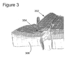
- Figure 3 depicts a gridded target horizon
- Figure 4 depicts a subset in common-reflection-point, common-reflection angle class
- Figure 5 depicts a subset in common-midpoint, common-offset class
- Figure 6 depicts a flowchart of a method embodiment
- FIGS. 7-10 depict various aspects of software components or modules which can be used to implement the embodiments.
- Figure 11 depicts an exemplary data processing device or system which can be used to implement the embodiments.
- methods and systems for preserving specular reflections on a depth target which, for example, match base and monitor datasets in common reflection point gathers. Such methods and systems can, for example, be used to enhance a 4D target signature.
- a data acquisition system 10 includes a ship 2 towing a plurality of streamers 6 that can extend one or more kilometers behind the ship 2.
- Each of the streamers 6 can include one or more birds 13 that maintain the streamer 6 in a known fixed position relative to other streamers 6, and the one or more birds 13 are capable of moving the streamers 6 as desired according to bi-directional communications received by the birds 13 from the ship 2.
- One or more source arrays 4a,b can also be towed by ship 2, or another ship, for generating seismic waves.
- Source arrays 4a,b can be placed either in front of or behind the receivers 14, or both behind and in front of the receivers 14.
- the seismic waves generated by the source arrays 4a,b propagate downward, reflect off of, and penetrate the seafloor, wherein the refracted waves eventually are reflected by one or more reflecting structures (not shown in Figure 1(a)) back to the surface (see Figure 2 , discussed below).
- the reflected seismic waves then propagate upward and are detected by the receivers 14 disposed on the streamers 6.
- the seismic waves then reflect off of the free surface, i.e., the surface of the body of water (see Figure 2 , discussed below), traveling downward and are once again detected by the receivers 14 disposed on streamers 6 as receiver ghosts.
- This process is generally referred to as "shooting" a particular seafloor area, with the seafloor area referred to as a "cell” and the sea surface referred to as a "free surface.”
- Figure 2 illustrates a side view of the data acquisition system 10 of Figure 1 .
- Ship 2 located on sea surface 46, tows one or more streamers 6, wherein the streamer 6 are comprised of cable 12c and a plurality of receivers 14.
- Shown in Figure 2 are two sources which include sources 4a,b attached to respective cables 12a,b.
- Each source 4a,b is capable of transmitting a respective sound wave, or transmitted signal 20a,b.
- a first pair of transmitted signals 20a,b will be shown (even though some or all of sources 4 can be simultaneously (or not) transmitting similar transmitted signals 20).
- First transmitted signal 20a,b travels through the sea 40 and arrives at first refraction/reflection point 22a,b.
- First reflected signal 24a,b from first transmitted signal 20a,b travels upward from the seafloor 42, and back to the receivers 14.
- a signal - optical or acoustical - travels from one medium with a first index of refraction n 1 and meets with a different medium, with a second index of refraction n 2
- a portion of the transmitted signal is reflected at an angle equal to the incident angle (according to the well-known Snell's law), and a second portion of the transmitted signal can be refracted (again according to Snell's law).
- first transmitted signal 20a,b generates first reflected signal 24a,b and first refracted signal 26a,b.
- First refracted signal 26a,b travels through sediment layer 16 (which can be generically referred to as first subsurface layer 16) beneath ocean floor 42, and can now be considered to be a "new" transmitted signal, such that when it encounters a second medium at second refraction/reflection point 28a,b, a second set of refracted and reflected signals 32a,b and 30a,b are subsequently generated.
- refracted 38a,b and reflected 36a,b signals are generated by the hydrocarbon deposit at the refraction/reflection point 34a,b and it is the purpose of data acquisition system 10 to generate data that can be used to discover such hydrocarbon deposits 44.
- the marine seismic acquisition system illustrated in Figures 1 and 2 is purely illustrative and that the following embodiments can be applied to seismic data acquired using different types of marine seismic acquisition systems. Indeed the following embodiments are also not limited to application to seismic data acquired by marine seismic acquisition systems, but can also be applied to other seismic data acquisitions including, but not limited to, land seismic acquisitions, ocean bottom nodes and cables, well seismics and mixed acquisitions (e.g., streamers with nodes data or surface with well data, etc.)
- the signals recorded by seismic receivers 14 vary in time, having energy peaks that may correspond to reflectors between layers. In reality, since the sea floor and the air/water are highly reflective, some of the peaks correspond to multiple reflections or spurious reflections that should be eliminated before the geophysical structure can be correctly imaged.
- Primary waves suffer only one reflection from an interface between layers of the subsurface (e.g., first reflected signal 24a). Waves other than primary waves are known as multiples.
- a surface multiple signal (not shown) is one such example of a multiple, however there are other ways for multiples to be generated. For example, reflections form the surface can travel back down to the receivers and be recorded as ghosts.
- the reflection points can correspond to primary waves or multiples raypath, or any raypath of any signature, as long it does correspond to reflected seismic energy.
- a tool or data processing component e.g., running on one or several processors in a computer system, which establishes a correspondence between source-receiver pairs in the acquisition system and reflection points.
- This data processing component operates to establish this correspondence based on wave propagation in the subsurface (e.g., ray tracing or detection from travel time maps along the horizon) and uses knowledge of a subsurface velocity model (or any approximation of it).
- wave propagation in the subsurface e.g., ray tracing or detection from travel time maps along the horizon
- a subsurface velocity model or any approximation of it.
- velocity models describe the expected speed of acoustic waves passing through the various layers of the subsurface region of interest, and are used for a number of purposes in processing acquired seismic data.
- the data collected and recorded by receivers 14 of Figure 1 can be processed by an embodiment to, among other things, preserve specular reflections on a depth target.
- the embodiment can perform target-oriented 4D binning in common reflection point wherein a depth target surface is defined at or in the vicinity of a location where 4D changes are expected, e.g., a reservoir horizon as depicted in Figure 3 .
- an embodiment presents a target horizon 302 on top of reservoir 306, gridded (meshed) into grid cells 304.
- a grid cell will also be denoted as a bin.
- a wave propagation method e.g. ray calculation or derivation from travel time maps
- s, r source-receiver pair
- x reflection bin cell
- a “reflection point” refers to the point on a subsurface interface where an acoustic wave generated by a source is reflected back toward a receiver.
- a “common reflection point” occurs when the reflection point for a one source-receiver pair is the same as that of one or more other source-receiver pairs. This correspondence between source-receiver pairs and reflection bin cells can be achieved, in an embodiment for example, with ray shooting in the known velocity model.
- Figure 4 depicts a subset in the common-reflection-point, common-reflection-angle class (defined by aperture and azimuth reflection angles, both of which are generically referenced by e in Figure 4 ) while Figure 5 depicts a subset in a common-midpoint, common-offset class.
- reflection angle in 3D (or 4D) seismic surveying actually is defined by two angles, i.e., an aperture angle and an azimuth angle.
- the common reflection angle class is thus defined by a range of aperture angles and azimuth angles.
- a subset of specular traces S(x, C) is sorted. It should be noted in the embodiment that all traces from S(x, C) carry reflective information from the target and should be preserved. Further in the embodiment, for each reflection bin cell 304, x ⁇ H and each class C, two subsets of specular traces S base ( x , C ) and S monitor ( x , C ) are collected from base and monitor surveys.
- target-oriented 4D binning in common-reflection point focuses on selecting and preserving the specular information from the depth target and this goal is achieved by selecting the most comparable traces within specular subsets of traces.
- selected traces T base ( x , C ) and T monitor ( x , C ) are defined in many possible ways, some of which are presented here.
- Second embodiment generate a stack from several or all traces within each subset, either with or without prior moveout correction based on the equations that follow:
- T base x ⁇ C ⁇ ij t base s i ⁇ r ij for all traces of subset t base s i ⁇ r ij ⁇ S base x ⁇ C
- T monitor x ⁇ C ⁇ kl t monitor s k ⁇ r kl for all traces of subset t monitor s k ⁇ r kl ⁇ S monitor x ⁇ C .
- dedicated 4D binning in common-reflection points can alternatively be carried out for different types of reflections, e.g., PP, PS, etc.
- the embodiments described herein are expected to improve the signal-to-noise ratio for higher reliability and enhancement of 4D changes along the target. It should be noted in the embodiment that these 4D changes along the target are otherwise known as a 4D target signature. Further benefits of the embodiments include, but are not limited to making 4D changes from trace-to-trace comparisons straightforward to map onto a target. Specular subsets can be used to reveal localized lack of illumination folds on the target, i.e., lack of or too few specular traces, which information is valuable for in-field design.
- the method embodiment selects, loads or inputs the surface of the depth target where 4D changes are expected. It should be noted in the method embodiment that the predicted depth target can be a reservoir horizon.
- the method embodiment establishes a correspondence between each of a plurality of source/receiver pairs and one of a plurality of reflection bins on the input surface. It should be noted in the method embodiment that the correspondence can be established with available techniques such as, but not limited to, ray shooting in the known velocity model.
- the method embodiment generates one or more sorted subsets of seismic traces, based on a plurality of reflection bins and a plurality of dataset classes. It should be noted in the method embodiment that the sorted traces carry reflective information from the depth target. It should further be noted in the method embodiment that the sorted traces are collected from both base surveys and monitor surveys.
- one or more seismic traces are selected from the subset of seismic traces. It should be noted in the method embodiment that for each reflection bin and each angle class (i.e. for given aperture and azimuth angles), a pairing can be generated based on a best fitting or best matching couple of traces or based on a stack of all traces within each subset, either with or without moveout correction.
- the selected seismic traces are output for further processing. It should be noted in the method embodiment that seismic traces comprise specular traces, PP traces, PS traces, etc.
- target oriented 4D binning node 700 comprises a surface component 702, a mapping component 704, a sorting component 706, a selection component 708, an output component 710 and seismic data 712.
- the surface prediction component 702 provides the capability to define a depth surface where 4D changes are expected. It should be noted in the exemplary embodiment that the surface can be a reservoir horizon or else.
- the mapping component 704 provides the capability to establish a correspondence between source/receiver seismic trace pairs of the seismic data 712 and reflection bins associated with the predicted depth surface. It should be noted in the embodiment that different techniques, well known in the art, are available for establishing the correspondence.
- the sorting component 706 provides the capability to sort seismic traces into subsets based on an associated reflection bin and a reflection class. It should be noted in the embodiment that the traces carry reflective information associated with the depth target.
- the selection component 708 provides the capability to select the most comparable traces that retain the best information from the seismic images associated with the depth target. It should be noted that the selections are made from the subsets associated with the reflection bins.
- the output component 710 provides the capability to output the selected seismic traces for further processing.
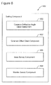
- an embodiment sorting component 706 comprises a common-reflection-angle class component 802, a common-offset class component 804, a base survey component 806 and a monitor survey component 808.
- the common-reflection-angle component 802 of the embodiment provides the capability to sort a common-reflection-angle class of seismic traces while the common-offset 804 component provides the capability to sort a common-offset class of seismic traces.
- the base survey component 806 provides for processing the seismic traces associated with the base survey and the monitor survey component 808 provides for processing the seismic traces associated with the monitor survey.
- a mapping component 704 further comprises a ray-shooting component 902.
- the embodiment ray-shooting component 902 provides the capability to establish a correspondence between each source/receiver trace pair and an associated reflection bin on a depth target.
- a selection component 708 further comprises a stack component 1002.
- the embodiment stack component 1002 provides the capability to stack several or all of the seismic traces associated with a subset. It should be noted in the embodiment that the stacking can occur either with or without a moveout correction.
- selection can be performed by, for example, for each reflection bin and each angle class (i.e. for given aperture and azimuth angles), generating a pairing of traces (one monitor trace and one baseline trace) based on a best fitting calculation or based on a stack of all traces within each subset, either with or without moveout correction
- the computing device(s) or other network nodes involved in target oriented 4D binning as set forth in the above described embodiments may be any type of computing device capable of processing and communicating seismic data associated with a seismic survey.
- An example of a representative computing system capable of carrying out operations in accordance with these embodiments is illustrated in Figure 11 .
- System 1100 includes, among other items, server 201, source/receiver interface 1402, internal data/communications bus (bus) 204, processor(s) 208 (those of ordinary skill in the art can appreciate that in modern server systems, parallel processing is becoming increasingly prevalent, and whereas a single processor would have been used in the past to implement many or at least several functions, it is more common currently to have a single dedicated processor for certain functions (e.g., digital signal processors) and therefore could be several processors, acting in serial and/or parallel, as required by the specific application), universal serial bus (USB) port 210, compact disk (CD)/digital video disk (DVD) read/write (R/W) drive 212, floppy diskette drive 214 (though less used currently, many servers still include this device), and data storage unit 232.
- USB universal serial bus
- Data storage unit 232 itself can comprise hard disk drive (HDD) 216 (these can include conventional magnetic storage media, but, as is becoming increasingly more prevalent, can include flash drive-type mass storage devices 224, among other types), ROM device(s) 218 (these can include electrically erasable (EE) programmable ROM (EEPROM) devices, ultra-violet erasable PROM devices (UVPROMs), among other types), and random access memory (RAM) devices 220.
- Usable with USB port 210 is flash drive device 224, and usable with CD/DVD R/W device 212 are CD/DVD disks 234 (which can be both read and write-able).
- Usable with diskette drive device 214 are floppy diskettes 237.
- Each of the memory storage devices, or the memory storage media can contain parts or components, or in its entirety, executable software programming code (software) 236 that can implement part or all of the portions of the method described herein.
- processor 208 itself can contain one or different types of memory storage devices (most probably, but not in a limiting manner, RAM memory storage media 220) that can store all or some of the components of software 236.
- system 200 also comprises user console 234, which can include keyboard 228, display 226, and mouse 230. All of these components are known to those of ordinary skill in the art, and this description includes all known and future variants of these types of devices.
- Display 226 can be any type of known display or presentation screen, such as liquid crystal displays (LCDs), light emitting diode displays (LEDs), plasma displays, cathode ray tubes (CRTs), among others.
- User console 235 can include one or more user interface mechanisms such as a mouse, keyboard, microphone, touch pad, touch screen, voice-recognition system, among other inter-active inter-communicative devices.
- System 200 can further include communications satellite/global positioning system (GPS) transceiver device 238, to which is electrically connected at least one antenna 240 (according to an exemplary embodiment, there would be at least one GPS receive-only antenna, and at least one separate satellite bi-directional communications antenna).
- GPS global positioning system
- System 200 can access internet 242, either through a hard wired connection, via I/O interface 222 directly, or wirelessly via antenna 240, and transceiver 238.
- Server 201 can be coupled to other computing devices, such as those that operate or control the equipment of ship 2, via one or more networks.
- Server 201 may be part of a larger network configuration as in a global area network (GAN) (e.g., internet 242), which ultimately allows connection to various landlines.
- GAN global area network
- system 200 being designed for use in seismic exploration, will interface with one or more sources 4a,b and one or more receivers 14. These, as previously described, are attached to streamers 6a,b, to which are also attached birds 13a,b that are useful to maintain positioning. As further previously discussed, sources 4 and receivers 14 can communicate with server 201 either through an electrical cable that is part of streamer 6, or via a wireless system that can communicate via antenna 240 and transceiver 238 (collectively described as communications conduit 246).
- user console 235 provides a means for personnel to enter commands and configuration into system 200 (e.g., via a keyboard, buttons, switches, touch screen and/or joy stick).
- Display device 226 can be used to show: streamer 6 position; visual representations of acquired data; source 4 and receiver 14 status information; survey information; and other information important to the seismic data acquisition process.
- Source and receiver interface unit 202 can receive the hydrophone seismic data from receiver 14 though streamer communication conduit 248 (discussed above) that can be part of streamer 6, as well as streamer 6 position information from birds 13; the link is bi-directional so that commands can also be sent to birds 13 to maintain proper streamer positioning.
- Source and receiver interface unit 202 can also communicate bi-directionally with sources 4 through the streamer communication conduit 248 that can be part of streamer 6. Excitation signals, control signals, output signals and status information related to source 4 can be exchanged by streamer communication conduit 248 between system 200 and source 4.
- Bus 204 allows a data pathway for items such as: the transfer and storage of data that originate from either the source sensors or streamer receivers; for processor 208 to access stored data contained in data storage unit memory 232; for processor 208 to send information for visual display to display 226; or for the user to send commands to system operating programs/software 236 that might reside in either the processor 208 or the source and receiver interface unit 202.
- System 200 can be used to implement the methods described above associated with target oriented 4D binning according to an embodiment.
- Hardware, firmware, software or a combination thereof may be used to perform the various steps and operations described herein.
- software 236 for carrying out the above discussed steps can be stored and distributed on multimedia storage devices such as devices 216, 218, 220, 224, 234, and/or 237 (described above) or other form of media capable of portably storing information (e.g., universal serial bus (USB) flash drive 426). These storage media may be inserted into, and read by, devices such as the CD-ROM drive 414, the disk drive 412, among other types of software storage devices.
- multimedia storage devices such as devices 216, 218, 220, 224, 234, and/or 237 (described above) or other form of media capable of portably storing information (e.g., universal serial bus (USB) flash drive 426).
- USB universal serial bus
- target oriented 4D binning can be processed and updated as the seismic data is recorded onboard the seismic vessel, once a new set of navigation lines has been acquired and at completion of the survey. In this case, it is possible for target oriented 4D binning to be computed as a measure of the quality of the sampling run.
- the disclosed exemplary embodiments provide a server node, and a method for target oriented 4D binning associated with seismic data. It should be understood that this description is not intended to limit the invention. On the contrary, the embodiments are intended to cover alternatives, modifications and equivalents, which are included in the spirit and scope of the invention. Further, in the detailed description of the embodiments, numerous specific details are set forth in order to provide a comprehensive understanding of the invention. However, one skilled in the art would understand that various embodiments may be practiced without such specific details.
- the embodiments described herein are primarily described in the context of towed streamer (marine) acquisition. However those skilled in the art will appreciate how to extend the described embodiments to other contexts, including, but not limited to land acquisition, Vertical Seismic Profiling, cross-well seismic, or ocean bottom 4-components sensors, such as Ocean Bottom Nodes or Ocean Bottom Cables or any mixed-type acquisition, which other embodiments are also considered to be included herein. In the latter case, the embodiments can be applied offline, as it is not easy to retrieve data from nodes during acquisition. However online QC may be performed in the case of Permanent Reservoir Monitoring Systems.
Landscapes
- Physics & Mathematics (AREA)
- Engineering & Computer Science (AREA)
- Remote Sensing (AREA)
- Life Sciences & Earth Sciences (AREA)
- Geology (AREA)
- Environmental & Geological Engineering (AREA)
- Acoustics & Sound (AREA)
- General Life Sciences & Earth Sciences (AREA)
- General Physics & Mathematics (AREA)
- Geophysics (AREA)
- Fluid Mechanics (AREA)
- Geophysics And Detection Of Objects (AREA)
- Measurement Of Velocity Or Position Using Acoustic Or Ultrasonic Waves (AREA)
Applications Claiming Priority (1)
| Application Number | Priority Date | Filing Date | Title |
|---|---|---|---|
| US201261738049P | 2012-12-17 | 2012-12-17 |
Publications (2)
| Publication Number | Publication Date |
|---|---|
| EP2743734A2 true EP2743734A2 (fr) | 2014-06-18 |
| EP2743734A3 EP2743734A3 (fr) | 2017-11-15 |
Family
ID=49759221
Family Applications (1)
| Application Number | Title | Priority Date | Filing Date |
|---|---|---|---|
| EP13197535.1A Withdrawn EP2743734A3 (fr) | 2012-12-17 | 2013-12-16 | Compartimentage 4D orientée cible dans un point de réflexion commun |
Country Status (4)
| Country | Link |
|---|---|
| US (1) | US9651693B2 (fr) |
| EP (1) | EP2743734A3 (fr) |
| AU (1) | AU2013273622A1 (fr) |
| MX (1) | MX340226B (fr) |
Cited By (1)
| Publication number | Priority date | Publication date | Assignee | Title |
|---|---|---|---|---|
| WO2014111389A3 (fr) * | 2013-01-15 | 2014-10-02 | Cgg Services Sa | Modélisation en champ d'ondes et classification 4d pour prospections sismiques avec différentes lignes de repère d'acquisition |
Families Citing this family (7)
| Publication number | Priority date | Publication date | Assignee | Title |
|---|---|---|---|---|
| CN104597483A (zh) * | 2013-02-04 | 2015-05-06 | 英洛瓦(天津)物探装备有限责任公司 | 使用混合模式的地震勘探系统获取地震数据的方法 |
| US10408958B2 (en) | 2015-07-22 | 2019-09-10 | Fairfield Industries Incorporated | Systems and methods for detecting subsurface features using 3D angle gathers |
| CN105549083B (zh) * | 2015-12-25 | 2018-03-13 | 中国石油天然气集团公司 | 一种确定地震观测系统重复性整体量度的方法和装置 |
| US10914853B2 (en) | 2017-03-16 | 2021-02-09 | Saudi Arabian Oil Company | Continuous seismic reservoir monitoring using a common focus point method |
| US11268352B2 (en) | 2019-04-01 | 2022-03-08 | Saudi Arabian Oil Company | Controlling fluid volume variations of a reservoir under production |
| US11460595B2 (en) | 2019-04-18 | 2022-10-04 | Saudi Arabian Oil Company | Unified continuous seismic reservoir monitoring |
| US11137510B2 (en) | 2019-04-23 | 2021-10-05 | Saudi Arabian Oil Company | Seismic reservoir monitoring using common transmission points |
Family Cites Families (14)
| Publication number | Priority date | Publication date | Assignee | Title |
|---|---|---|---|---|
| US3531763A (en) | 1965-06-02 | 1970-09-29 | Atlantic Richfield Co | Restricted stacking on shallow reflections |
| GB1377812A (en) | 1971-03-10 | 1974-12-18 | Petty Ray Geophysical Inc | Method and apparatus for seismic processing |
| US4802147A (en) | 1985-05-23 | 1989-01-31 | Mobil Oil Corporation | Method for segregating and stacking vertical seismic profile data in common reflection point bins |
| US4894809A (en) | 1985-05-23 | 1990-01-16 | Mobil Oil Corporation | Method for bin, moveout correction and stack of offset vertical seismic profile data in media with dip |
| US4953142A (en) | 1989-01-06 | 1990-08-28 | Marathon Oil Company | Model-based depth processing of seismic data |
| US4964103A (en) | 1989-07-13 | 1990-10-16 | Conoco Inc. | Three dimensional before stack depth migration of two dimensional or three dimensional seismic data |
| US6442490B1 (en) | 2000-06-30 | 2002-08-27 | Pgs Americas, Inc. | Vertical cable time processing |
| US7768872B2 (en) | 2004-07-23 | 2010-08-03 | Ion Geophysical Corporation | Offset-azimuth binning for migration and velocity analysis |
| GB2420408B (en) * | 2004-11-19 | 2008-03-12 | Geophysique Cie Gle | Method for processing at least two sets of seismic data |
| US7477992B2 (en) | 2005-02-18 | 2009-01-13 | Exxonmobil Upstream Research Company | Method for combining seismic data sets |
| US8339898B2 (en) * | 2008-05-25 | 2012-12-25 | Westerngeco L.L.C. | Processing seismic data using combined regularization and 4D binning |
| AU2009333601B2 (en) * | 2008-12-17 | 2014-08-21 | Exxonmobil Upstream Research Company | Method for imaging of targeted reflectors |
| US8913462B2 (en) | 2009-04-03 | 2014-12-16 | Schlumberger Technology Corporation | Real-time reflection point density mapping during three-dimensional (3D) vertical seismic profile (VSP) surveys |
| CN102736109B (zh) | 2012-06-08 | 2015-01-21 | 中国石油大学(华东) | 一种crp道集去噪、校正与叠加的方法 |
-
2013
- 2013-12-16 EP EP13197535.1A patent/EP2743734A3/fr not_active Withdrawn
- 2013-12-16 US US14/107,444 patent/US9651693B2/en not_active Expired - Fee Related
- 2013-12-17 AU AU2013273622A patent/AU2013273622A1/en not_active Abandoned
- 2013-12-17 MX MX2013015015A patent/MX340226B/es active IP Right Grant
Non-Patent Citations (1)
| Title |
|---|
| None |
Cited By (2)
| Publication number | Priority date | Publication date | Assignee | Title |
|---|---|---|---|---|
| WO2014111389A3 (fr) * | 2013-01-15 | 2014-10-02 | Cgg Services Sa | Modélisation en champ d'ondes et classification 4d pour prospections sismiques avec différentes lignes de repère d'acquisition |
| US9684085B2 (en) | 2013-01-15 | 2017-06-20 | Cgg Services Sas | Wavefield modelling and 4D-binning for seismic surveys from different acquisition datums |
Also Published As
| Publication number | Publication date |
|---|---|
| US20140172307A1 (en) | 2014-06-19 |
| MX2013015015A (es) | 2014-08-06 |
| AU2013273622A1 (en) | 2014-07-03 |
| MX340226B (es) | 2016-06-30 |
| US9651693B2 (en) | 2017-05-16 |
| EP2743734A3 (fr) | 2017-11-15 |
Similar Documents
| Publication | Publication Date | Title |
|---|---|---|
| EP2946232B1 (fr) | Modélisation en champ d'ondes et classification 4d pour prospections sismiques avec différentes lignes de repère d'acquisition | |
| US9651693B2 (en) | Target-oriented 4D binning in common reflection point | |
| US9435905B2 (en) | Premigration deghosting of seismic data with a bootstrap technique | |
| US10310123B2 (en) | Seismic reflection full waveform inversion for reflected seismic data | |
| US9477000B2 (en) | System and method for the removal of shallow water multiples using a hybrid multi-channel prediction method | |
| AU2015218416B2 (en) | Impact assessment of marine seismic surveys | |
| EP3059615B1 (fr) | Analyse amplitude-versus-angle pour une interprétation quantitative | |
| US20020072856A1 (en) | Quality control cube for seismic data | |
| US9746567B2 (en) | Systems and methods for performing dual-scale interpolation | |
| Crutchley et al. | Reflection and refraction seismic methods | |
| US9733374B2 (en) | Repeatability indicator based on shot illumination for seismic acquisition | |
| US9798025B2 (en) | Regularization of multi-component seismic data | |
| EP2743737A2 (fr) | Procédés et systèmes pour le contrôle de la qualité de cartes d'éclairage sismique | |
| US10324208B2 (en) | Premigration deghosting for marine streamer data using a bootstrap approach in Tau-P domain | |
| US20140297191A1 (en) | Predicting sensitivity to positioning for seismic surveys | |
| AU2014201749A1 (en) | Seismic systems and methods employing repeatability shot indicators | |
| Li | The Challenges and Solutions of Green Seismic Survey: Imaging Deep Seafloor Structures with Cruise TN-373 Reflection Data | |
| BR102013032535A2 (pt) | compartimentação 4d orientada a alvo em ponto de reflexão comum | |
| MX2013015014A (es) | Metodos y sistemas para control de calidad de mapas de iluminacion sismicos. |
Legal Events
| Date | Code | Title | Description |
|---|---|---|---|
| PUAI | Public reference made under article 153(3) epc to a published international application that has entered the european phase |
Free format text: ORIGINAL CODE: 0009012 |
|
| 17P | Request for examination filed |
Effective date: 20131216 |
|
| AK | Designated contracting states |
Kind code of ref document: A2 Designated state(s): AL AT BE BG CH CY CZ DE DK EE ES FI FR GB GR HR HU IE IS IT LI LT LU LV MC MK MT NL NO PL PT RO RS SE SI SK SM TR |
|
| AX | Request for extension of the european patent |
Extension state: BA ME |
|
| PUAL | Search report despatched |
Free format text: ORIGINAL CODE: 0009013 |
|
| AK | Designated contracting states |
Kind code of ref document: A3 Designated state(s): AL AT BE BG CH CY CZ DE DK EE ES FI FR GB GR HR HU IE IS IT LI LT LU LV MC MK MT NL NO PL PT RO RS SE SI SK SM TR |
|
| AX | Request for extension of the european patent |
Extension state: BA ME |
|
| RIC1 | Information provided on ipc code assigned before grant |
Ipc: G01V 1/30 20060101AFI20171010BHEP |
|
| STAA | Information on the status of an ep patent application or granted ep patent |
Free format text: STATUS: THE APPLICATION IS DEEMED TO BE WITHDRAWN |
|
| 18D | Application deemed to be withdrawn |
Effective date: 20180516 |