EP2744072A2 - Motor - Google Patents
Motor Download PDFInfo
- Publication number
- EP2744072A2 EP2744072A2 EP13196475.1A EP13196475A EP2744072A2 EP 2744072 A2 EP2744072 A2 EP 2744072A2 EP 13196475 A EP13196475 A EP 13196475A EP 2744072 A2 EP2744072 A2 EP 2744072A2
- Authority
- EP
- European Patent Office
- Prior art keywords
- motor
- tip portion
- teeth
- stator core
- stator
- Prior art date
- Legal status (The legal status is an assumption and is not a legal conclusion. Google has not performed a legal analysis and makes no representation as to the accuracy of the status listed.)
- Withdrawn
Links
Images


Classifications
-
- H—ELECTRICITY
- H02—GENERATION; CONVERSION OR DISTRIBUTION OF ELECTRIC POWER
- H02K—DYNAMO-ELECTRIC MACHINES
- H02K1/00—Details of the magnetic circuit
- H02K1/06—Details of the magnetic circuit characterised by the shape, form or construction
- H02K1/12—Stationary parts of the magnetic circuit
- H02K1/14—Stator cores with salient poles
-
- H—ELECTRICITY
- H02—GENERATION; CONVERSION OR DISTRIBUTION OF ELECTRIC POWER
- H02K—DYNAMO-ELECTRIC MACHINES
- H02K1/00—Details of the magnetic circuit
- H02K1/06—Details of the magnetic circuit characterised by the shape, form or construction
- H02K1/12—Stationary parts of the magnetic circuit
- H02K1/16—Stator cores with slots for windings
- H02K1/165—Shape, form or location of the slots
-
- H—ELECTRICITY
- H02—GENERATION; CONVERSION OR DISTRIBUTION OF ELECTRIC POWER
- H02K—DYNAMO-ELECTRIC MACHINES
- H02K2201/00—Specific aspects not provided for in the other groups of this subclass relating to the magnetic circuits
- H02K2201/03—Machines characterised by aspects of the air-gap between rotor and stator
Definitions
- the present invention relates to a motor, and more particularly, to an electronic power steering (EPS) motor.
- EPS electronic power steering
- a steering system which is a device for ensuring steering stability of a vehicle functions to help a driver of the vehicle to steer with separate power.
- An EPS system includes a speed sensor, a torque angle sensor, and a torque sensor.
- An electronic control unit detects driving conditions by using the sensors included in the EPS system, and drives a motor according to the detected driving conditions. Accordingly, cornering stability may be ensured and a rapid restoring force may be provided, thereby making it possible for a driver to safely drive a vehicle.
- a motor (hereinafter, referred to as an "EPS motor”) of the EPS system assists torque of a steering wheel so that the driver may steer more efficiently.
- a brushless direct current (BLDC) motor may be used as the EPS motor.
- the BLDC motor is a direct current (DC) motor including an electronic commutation mechanism instead of a mechanical contact unit such as a brush or a commutator.
- the EPS motor includes a housing whose top is open and a bracket that is coupled to the top of the housing to form an exterior appearance of the EPS motor.
- a rotor and a stator are received in the housing.
- the rotor includes a rotor core and a magnet, and is assembled to surround a rotating shaft.
- the stator includes a stator core and a coil, and is fixed to an inner circumferential surface of the housing to surround an outer circumferential surface of the rotor.
- the rotating shaft rotates along with the rotor due to electromagnetic interaction between the rotor and the stator.
- a plurality of teeth are radially formed along an inner circumferential surface of the stator core.
- a slot into which the coil is inserted is formed between adjacent teeth, and both sides of an end of each of the teeth protrude toward an adjacent tooth to form a slot opening.
- a magnetic loss component is determined according to a size of a slot opening when a motor is designed.
- a width of the slot opening decreases, magnetic loss increases and thus motor output decreases, but cogging torque decreases.
- the width of the slot opening increases, magnetic loss decreases and thus motor output increases, but cogging torque increases.
- the size of the slot opening may vary according to a motor model.
- Cogging torque is defined as a ripple of torque which is necessarily produced in a state where power is not supplied to a motor having a tooth-slot structure.
- the cogging torque acts as one factor that causes noise and vibration in a motor, and is seriously managed in a motor that requires high perceived quality such as a steering motor.
- the present invention is directed to a motor that may reduce cogging torque.
- a motor including a stator that includes a stator core and a coil that is wound around the stator core, and a rotor that is rotatably disposed in the stator, wherein the stator core includes a plurality of teeth that are radially formed along an inner circumferential surface of the stator core, a plurality of shoes that extend in a circumferential direction from both sides of an end of each of the plurality of teeth, and a tip portion that extends in the circumferential direction from an end of each of the plurality of shoes to contact a tip portion of an adjacent tooth.
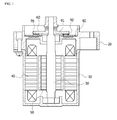
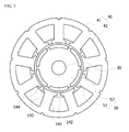
- FIGS. 1 and 2 are respectively a longitudinal-sectional view and a cross-sectional view illustrating a general electronic power steering (EPS) motor.
- EPS electronic power steering
- the general EPS motor includes a housing 10, a bracket 20, a rotating shaft 30, a stator 40, and a rotor 50.
- the housing 10 has a substantially cylindrical shape whose top is open, and the stator 40 and the rotor 50 are coupled to a space in the housing 10. Also, the bracket 20 is coupled to the top of the housing 10 to form an exterior appearance of the general EPS motor.
- the rotating shaft 30 is rotatably supported by the housing 10 and the bracket 20.
- a steering column of a vehicle is connected to the top of the rotating shaft 30 to provide power that helps a driver to steer as described above.
- the rotor 50 into which a plurality of magnets are inserted is coupled to an outer circumferential surface of the rotating shaft 30.
- the stator 40 including a core 41 and a coil 43 is coupled to an inner circumferential surface of the housing 10 to provide an electromagnetic force on an outer circumferential surface of the rotor 50.
- the stator 40 is disposed on the inner circumferential surface of the housing 10.
- the stator 40 includes a stator core 41 (see FIG. 2 ), an insulator 42, and a coil 43 that are wound around the stator core 41.
- the stator core 41 has a substantially annular shape, and may be formed by stacking a plurality of silicon steel plates.
- a plurality of teeth 141 are radially formed along an inner circumferential surface of the stator core 41.
- a slot 142 into which the coil 43 is inserted is disposed between adjacent teeth of the plurality of teeth 141. Adjacent teeth of the plurality of teeth 141 are spaced apart from each other by a predetermined interval due to the slot 142.
- Each of shoes 144 protrudes in a circumferential direction from an end of each of the teeth 141. Adjacent shoes of the shoes 144 are spaced apart from each other to form a slot opening 143.
- the rotor 50 is coupled to the rotating shaft 30 to surround the outer circumferential surface of the rotating shaft 30, and is disposed in the stator 40.
- the rotor 50 includes a rotor core 51 and a plurality of magnets 52.
- the rotor core 51 has a substantially cylindrical shape, and may be formed by stacking a plurality of silicon steel plates.
- a through-hole is axially formed in a central portion of the rotor core 51, and the rotating shaft 30 passes through and is fixed to the through-hole.
- the plurality of magnets 52 are buried along an outer circumferential surface of the rotor core 51 such that adjacent magnets of the magnets 52 are spaced apart from each other.
- the steering column may also rotate due to the rotation of the rotating shaft 30. Accordingly, the general EPS motor helps the steering column to rotate as the driver swivels a steering wheel.
- a printed circuit board (PCB) 80 is coupled to a top surface of the bracket 20.
- Sensors 91 and 92 are disposed on a top surface of the PCB 80.
- the sensors 91 and 92 output a sensing signal that is used to calculate a rotation angle of the rotor 50 by detecting a change in polarity or magnetic flux of a sensing magnet 70.
- Each of the sensors 91 and 92 may be implemented with a hall integrated circuit (IC), and an encoder IC.
- a plate 60 is disposed over the PCB 80 to face the PCB 80 and to be spaced apart from the PCB 80 by a predetermined interval.
- the plate 60 is coupled to the rotating shaft 30 to rotate along with the rotating shaft 30.
- the sensing magnet 70 is disposed under the plate 60 to face the sensors 91 and 92 that are disposed on the top surface of the PCB 80.
- the sensing magnet 70 is coupled to the rotating shaft 30 and rotates along with the rotating shaft 30.
- the size of the slot opening may vary according to a motor model.
- cogging torque is critically managed in a motor that requires high perceived quality such as an EPS motor.
- an EPS motor that may reduce cogging torque by eliminating a slot opening of each slot.
- a motor is an EPS motor
- the EPS motor includes a housing, a bracket that is coupled to the top of the housing, a rotating shaft that is supported by the housing and the bracket, a stator that is coupled to an inner circumferential surface of the housing, and a rotor that is coupled to an outer circumferential surface of the rotating shaft.
- FIG. 3 is a cross-sectional view illustrating an EPS motor according to an embodiment of the present invention. Also, FIG. 4 is an enlarged cross-sectional view illustrating the stator core 41 of the EPS motor of FIG. 3 .
- the stator core 41 has a substantially annular shape, and is formed by stacking a plurality of silicon steel plates.
- a plurality of teeth 151 are radially formed along an inner circumferential surface of the stator core 41.
- a slot 152 into which a coil is inserted is disposed between adjacent teeth of the plurality of teeth 151.
- the plurality of teeth 151 are formed such that adjacent teeth are spaced apart from each other by a predetermined interval due to the slot 152.
- shoes 161, and tip portions 162 are integrally formed with each other.
- the shoes 161 extend in a circumferential direction from both sides of an end of each of the teeth 151 facing an outer circumferential surface of the rotor 50. Also, the tip portions 162 extend in the circumferential direction from an end of each of the shoes 161 to contact tip portions of an adjacent tooth. The tip portions 162 are formed such that an end portion of each of the tip portions 162 and an end portion of each of the shoes 161 form a right angle therebetween, and maintain a predetermined thickness in the circumferential direction.
- the slot 152 that is formed between adjacent teeth of the teeth 151 is formed to have no opening because the tip portion 162 closes the opening. Accordingly, a magnetic reluctance difference that may cause cogging torque may be removed.
- a thickness h1 of the tip portion 162 in a radial direction is less than a thickness of the shoe 161 in the radial direction.
- the tip portion 162 may be formed to have a minimum thickness which a press forming method allows when the stator core 41 is manufactured using the press forming method.
- the thickness h1 of the tip portion 162 in the radial direction may be, for example, 0.5 mm.
- magnetic loss that may occur due to leakage flux flowing to an adjacent tooth may be minimized, thereby preventing rated torque from being reduced.
- the tip portion 162 no longer functions as a magnetic body, and functions to suppress a flow of leakage flux using magnetic permeability that is similar to that of air.
- the reduction in the magnetic loss further increases as a length w1 of the tip portion 162 in the circumferential direction increases.
- FIG. 5 is a cross-sectional view illustrating an EPS motor according to another embodiment of the present invention. Also, FIG. 6 is an enlarged cross-sectional view illustrating the stator core 41 of the EPS motor of FIG. 5 .
- the stator core 41 has a substantially annular shape, and is formed by stacking a plurality of silicon steel plates.
- a plurality of teeth 171 are radially formed along an inner circumferential surface of the stator core 41.
- a slot 172 into which a coil is inserted is disposed between adjacent teeth of the plurality of teeth 171.
- the plurality of teeth 171 are formed such that adjacent teeth are spaced apart from each other by a predetermined interval due to the slot 172.
- teeth 171, shoes 181, and tip portions 182 are integrally formed with each other.
- the shoes 181 extend in a circumferential direction from an end of each of the teeth 171 facing an outer circumferential surface of the rotor 50. Also, the tip portions 182 extend from an end of each of the shoes 181 to contact tip portions of an adjacent tooth. The tip portions 182 are formed such that a thickness of each of the tip portions 182 decreases away from an end portion of each of the shoes 181, thereby having a sharp end.
- the slot 172 that is formed between adjacent teeth of the teeth 171 is formed such that an opening is closed by the tip portion 182. Accordingly, a magnetic reluctance difference that may cause cogging torque may be removed.
- the tip portion 182 may be formed such that a maximum thickness h2 in a radial direction of the tip portion 182 has a minimum thickness which a press forming method allows when the stator core 41 is manufactured using the press forming method.
- the thickness h2 of the tip portion 182 may be, for example, 0.5 mm.
- the tip portion 182 no longer functions as a magnetic body, and functions to suppress a flow of leakage flux using magnetic permeability that is similar to that of air.
- the reduction in the magnetic loss further increases as a length w2 of the tip portion 182 in the circumferential direction increases.
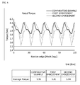
- FIGS. 7 and 8 are views for describing effects of the EPS motors of FIGS. 3 and 5 .
- FIG. 7 is a graph illustrating a result obtained by comparing cogging torques of the general EPS motor of FIG. 2 and the EPS motors of FIGS. 3 and 5 .
- FIG. 8 is a graph illustrating a result obtained by comparing rated torques of the general EPS motor of FIG. 2 , and the EPS motors of FIGS. 3 and 5 .
- rated torques of the EPS motors of FIGS. 3 and 5 are slightly less than that of the general EPS motor of FIG. 2 .
- the EPS motors of FIGS. 3 and 5 greatly reduce cogging torque while maintaining rated torque that is almost similar to that of the general EPS motor of FIG. 2 .
- a motor according to the one or more embodiments of the present invention may almost constantly maintain rated torque and greatly reduce cogging torque compared to an existing motor.
Landscapes
- Engineering & Computer Science (AREA)
- Power Engineering (AREA)
- Iron Core Of Rotating Electric Machines (AREA)
- Power Steering Mechanism (AREA)
Applications Claiming Priority (1)
| Application Number | Priority Date | Filing Date | Title |
|---|---|---|---|
| KR1020120147321A KR20140078217A (ko) | 2012-12-17 | 2012-12-17 | 모터 |
Publications (2)
| Publication Number | Publication Date |
|---|---|
| EP2744072A2 true EP2744072A2 (de) | 2014-06-18 |
| EP2744072A3 EP2744072A3 (de) | 2016-08-10 |
Family
ID=49726633
Family Applications (1)
| Application Number | Title | Priority Date | Filing Date |
|---|---|---|---|
| EP13196475.1A Withdrawn EP2744072A3 (de) | 2012-12-17 | 2013-12-10 | Motor |
Country Status (5)
| Country | Link |
|---|---|
| US (1) | US20140167557A1 (de) |
| EP (1) | EP2744072A3 (de) |
| JP (1) | JP2014121263A (de) |
| KR (1) | KR20140078217A (de) |
| CN (1) | CN103872807A (de) |
Families Citing this family (6)
| Publication number | Priority date | Publication date | Assignee | Title |
|---|---|---|---|---|
| JP2016116391A (ja) * | 2014-12-17 | 2016-06-23 | サンデンホールディングス株式会社 | コンプレッサ用モータ及びそれを備えたコンプレッサ |
| CN106300714A (zh) * | 2016-09-08 | 2017-01-04 | 珠海凌达压缩机有限公司 | 定子铁芯、电机及空调器 |
| DE102017216633A1 (de) * | 2017-09-20 | 2019-03-21 | Continental Automotive Gmbh | Elektrische Maschine |
| EP3745559B1 (de) * | 2019-05-27 | 2022-03-09 | Magnax Bv | Stator für eine axialflussmaschine |
| CN110581610B (zh) * | 2019-08-29 | 2025-03-07 | 珠海凌达压缩机有限公司 | 一种辅助槽定子冲片、定子组件、电机、压缩机 |
| DE102021106186A1 (de) * | 2021-03-15 | 2022-09-15 | Ebm-Papst Mulfingen Gmbh & Co. Kg | Modular aufgebautes, segmentiertes Statorpaket |
Family Cites Families (8)
| Publication number | Priority date | Publication date | Assignee | Title |
|---|---|---|---|---|
| US3169203A (en) * | 1961-03-28 | 1965-02-09 | Ibm | Square wave pulse generator |
| DE10152499A1 (de) * | 2001-10-24 | 2003-05-08 | Pierburg Gmbh | Elektromotor |
| JP2003264947A (ja) * | 2002-03-08 | 2003-09-19 | Fujitsu General Ltd | 永久磁石電動機 |
| JP3744461B2 (ja) * | 2002-04-26 | 2006-02-08 | 株式会社デンソー | 回転電機のステータ |
| JP2004096803A (ja) * | 2002-08-29 | 2004-03-25 | Mitsubishi Electric Corp | 永久磁石同期モータ |
| DE102007032872A1 (de) * | 2007-07-12 | 2009-01-15 | Ipgate Ag | Stator für Elektromotor |
| CN103493337B (zh) * | 2011-06-30 | 2016-12-28 | D·R·麦金托什 | 低成本低齿槽效应的永磁电机 |
| CN103259351A (zh) * | 2013-05-13 | 2013-08-21 | 广东威灵电机制造有限公司 | 永磁电机 |
-
2012
- 2012-12-17 KR KR1020120147321A patent/KR20140078217A/ko not_active Withdrawn
-
2013
- 2013-12-10 EP EP13196475.1A patent/EP2744072A3/de not_active Withdrawn
- 2013-12-11 JP JP2013256045A patent/JP2014121263A/ja active Pending
- 2013-12-16 CN CN201310688338.6A patent/CN103872807A/zh active Pending
- 2013-12-17 US US14/109,113 patent/US20140167557A1/en not_active Abandoned
Non-Patent Citations (1)
| Title |
|---|
| None |
Also Published As
| Publication number | Publication date |
|---|---|
| JP2014121263A (ja) | 2014-06-30 |
| KR20140078217A (ko) | 2014-06-25 |
| EP2744072A3 (de) | 2016-08-10 |
| CN103872807A (zh) | 2014-06-18 |
| US20140167557A1 (en) | 2014-06-19 |
Similar Documents
| Publication | Publication Date | Title |
|---|---|---|
| EP2744087B1 (de) | Motor und Magneterfassung davon | |
| US9490673B2 (en) | Rotor of magnet-assisted reluctance motor and brushless motor | |
| EP2744072A2 (de) | Motor | |
| EP3509187B1 (de) | Stator und motor damit | |
| JP2008206354A (ja) | ブラシレスモータ | |
| EP3139478B1 (de) | Dauermagnetmotor | |
| EP2747247A2 (de) | Stator und Motor damit | |
| JP2008301601A (ja) | ブラシレスモータ | |
| JP6385854B2 (ja) | ブラシレスモータ | |
| JP6870989B2 (ja) | ロータおよび電動モータ | |
| WO2020054095A1 (ja) | 電動モータおよび電動モータの製造方法 | |
| JP4772139B2 (ja) | 電動パワーステアリング装置用モータ装置 | |
| JP2009153269A (ja) | ブラシレスモータ | |
| JP2013005659A (ja) | 電動モータ | |
| JP5155632B2 (ja) | ブラシレスモータ | |
| EP2680409A2 (de) | Motor | |
| EP2228886B1 (de) | Elektrischer Motor | |
| JP2007228736A (ja) | モータ | |
| JP2006197786A (ja) | ブラシレスモータ | |
| JP2008220008A (ja) | ブラシレスモータ及び流体ポンプ装置 | |
| KR20120018661A (ko) | 코깅 토크 저감 구조를 가진 eps모터 | |
| EP2744085B1 (de) | Schraubenmotor | |
| KR20180007089A (ko) | 로터 및 이를 포함하는 모터 | |
| JP2021083144A (ja) | 回転電機 | |
| JP2008306859A (ja) | ステータコア |
Legal Events
| Date | Code | Title | Description |
|---|---|---|---|
| PUAI | Public reference made under article 153(3) epc to a published international application that has entered the european phase |
Free format text: ORIGINAL CODE: 0009012 |
|
| 17P | Request for examination filed |
Effective date: 20140327 |
|
| AK | Designated contracting states |
Kind code of ref document: A2 Designated state(s): AL AT BE BG CH CY CZ DE DK EE ES FI FR GB GR HR HU IE IS IT LI LT LU LV MC MK MT NL NO PL PT RO RS SE SI SK SM TR |
|
| AX | Request for extension of the european patent |
Extension state: BA ME |
|
| PUAL | Search report despatched |
Free format text: ORIGINAL CODE: 0009013 |
|
| AK | Designated contracting states |
Kind code of ref document: A3 Designated state(s): AL AT BE BG CH CY CZ DE DK EE ES FI FR GB GR HR HU IE IS IT LI LT LU LV MC MK MT NL NO PL PT RO RS SE SI SK SM TR |
|
| AX | Request for extension of the european patent |
Extension state: BA ME |
|
| RIC1 | Information provided on ipc code assigned before grant |
Ipc: H02K 1/16 20060101AFI20160706BHEP |
|
| RAP1 | Party data changed (applicant data changed or rights of an application transferred) |
Owner name: LG INNOTEK CO., LTD. |
|
| STAA | Information on the status of an ep patent application or granted ep patent |
Free format text: STATUS: THE APPLICATION IS DEEMED TO BE WITHDRAWN |
|
| 18D | Application deemed to be withdrawn |
Effective date: 20170211 |