EP2745779A2 - Kapillar-mikroküvette mit doppeltem auffangmittel - Google Patents
Kapillar-mikroküvette mit doppeltem auffangmittel Download PDFInfo
- Publication number
- EP2745779A2 EP2745779A2 EP12824276.5A EP12824276A EP2745779A2 EP 2745779 A2 EP2745779 A2 EP 2745779A2 EP 12824276 A EP12824276 A EP 12824276A EP 2745779 A2 EP2745779 A2 EP 2745779A2
- Authority
- EP
- European Patent Office
- Prior art keywords
- microcuvette
- sample
- cavity
- capillary
- body member
- Prior art date
- Legal status (The legal status is an assumption and is not a legal conclusion. Google has not performed a legal analysis and makes no representation as to the accuracy of the status listed.)
- Granted
Links
Images


Classifications
-
- G—PHYSICS
- G01—MEASURING; TESTING
- G01N—INVESTIGATING OR ANALYSING MATERIALS BY DETERMINING THEIR CHEMICAL OR PHYSICAL PROPERTIES
- G01N21/00—Investigating or analysing materials by the use of optical means, i.e. using sub-millimetre waves, infrared, visible or ultraviolet light
- G01N21/01—Arrangements or apparatus for facilitating the optical investigation
- G01N21/11—Filling or emptying of cuvettes
-
- A—HUMAN NECESSITIES
- A61—MEDICAL OR VETERINARY SCIENCE; HYGIENE
- A61B—DIAGNOSIS; SURGERY; IDENTIFICATION
- A61B5/00—Measuring for diagnostic purposes; Identification of persons
- A61B5/15—Devices for taking samples of blood
- A61B5/157—Devices characterised by integrated means for measuring characteristics of blood
-
- A—HUMAN NECESSITIES
- A61—MEDICAL OR VETERINARY SCIENCE; HYGIENE
- A61B—DIAGNOSIS; SURGERY; IDENTIFICATION
- A61B5/00—Measuring for diagnostic purposes; Identification of persons
- A61B5/14—Devices for taking samples of blood ; Measuring characteristics of blood in vivo, e.g. gas concentration within the blood, pH-value of blood
- A61B5/1405—Devices for taking blood samples
-
- A—HUMAN NECESSITIES
- A61—MEDICAL OR VETERINARY SCIENCE; HYGIENE
- A61B—DIAGNOSIS; SURGERY; IDENTIFICATION
- A61B5/00—Measuring for diagnostic purposes; Identification of persons
- A61B5/14—Devices for taking samples of blood ; Measuring characteristics of blood in vivo, e.g. gas concentration within the blood, pH-value of blood
- A61B5/1405—Devices for taking blood samples
- A61B5/1411—Devices for taking blood samples by percutaneous method, e.g. by lancet
-
- A—HUMAN NECESSITIES
- A61—MEDICAL OR VETERINARY SCIENCE; HYGIENE
- A61B—DIAGNOSIS; SURGERY; IDENTIFICATION
- A61B5/00—Measuring for diagnostic purposes; Identification of persons
- A61B5/15—Devices for taking samples of blood
- A61B5/150007—Details
- A61B5/150015—Source of blood
- A61B5/150022—Source of blood for capillary blood or interstitial fluid
-
- A—HUMAN NECESSITIES
- A61—MEDICAL OR VETERINARY SCIENCE; HYGIENE
- A61B—DIAGNOSIS; SURGERY; IDENTIFICATION
- A61B5/00—Measuring for diagnostic purposes; Identification of persons
- A61B5/15—Devices for taking samples of blood
- A61B5/150007—Details
- A61B5/150206—Construction or design features not otherwise provided for; manufacturing or production; packages; sterilisation of piercing element, piercing device or sampling device
- A61B5/150213—Venting means
-
- A—HUMAN NECESSITIES
- A61—MEDICAL OR VETERINARY SCIENCE; HYGIENE
- A61B—DIAGNOSIS; SURGERY; IDENTIFICATION
- A61B5/00—Measuring for diagnostic purposes; Identification of persons
- A61B5/15—Devices for taking samples of blood
- A61B5/150007—Details
- A61B5/150343—Collection vessels for collecting blood samples from the skin surface, e.g. test tubes, cuvettes
-
- B—PERFORMING OPERATIONS; TRANSPORTING
- B01—PHYSICAL OR CHEMICAL PROCESSES OR APPARATUS IN GENERAL
- B01L—CHEMICAL OR PHYSICAL LABORATORY APPARATUS FOR GENERAL USE
- B01L3/00—Containers or dishes for laboratory use, e.g. laboratory glassware; Droppers
- B01L3/50—Containers for the purpose of retaining a material to be analysed, e.g. test tubes
- B01L3/502—Containers for the purpose of retaining a material to be analysed, e.g. test tubes with fluid transport, e.g. in multi-compartment structures
- B01L3/5027—Containers for the purpose of retaining a material to be analysed, e.g. test tubes with fluid transport, e.g. in multi-compartment structures by integrated microfluidic structures, i.e. dimensions of channels and chambers are such that surface tension forces are important, e.g. lab-on-a-chip
- B01L3/502715—Containers for the purpose of retaining a material to be analysed, e.g. test tubes with fluid transport, e.g. in multi-compartment structures by integrated microfluidic structures, i.e. dimensions of channels and chambers are such that surface tension forces are important, e.g. lab-on-a-chip characterised by interfacing components, e.g. fluidic, electrical, optical or mechanical interfaces
-
- G—PHYSICS
- G01—MEASURING; TESTING
- G01N—INVESTIGATING OR ANALYSING MATERIALS BY DETERMINING THEIR CHEMICAL OR PHYSICAL PROPERTIES
- G01N21/00—Investigating or analysing materials by the use of optical means, i.e. using sub-millimetre waves, infrared, visible or ultraviolet light
- G01N21/01—Arrangements or apparatus for facilitating the optical investigation
- G01N21/03—Cuvette constructions
-
- G—PHYSICS
- G01—MEASURING; TESTING
- G01N—INVESTIGATING OR ANALYSING MATERIALS BY DETERMINING THEIR CHEMICAL OR PHYSICAL PROPERTIES
- G01N33/00—Investigating or analysing materials by specific methods not covered by groups G01N1/00 - G01N31/00
- G01N33/48—Biological material, e.g. blood, urine; Haemocytometers
- G01N33/483—Physical analysis of biological material
- G01N33/487—Physical analysis of biological material of liquid biological material
- G01N33/49—Blood
-
- A—HUMAN NECESSITIES
- A61—MEDICAL OR VETERINARY SCIENCE; HYGIENE
- A61B—DIAGNOSIS; SURGERY; IDENTIFICATION
- A61B10/00—Instruments for taking body samples for diagnostic purposes; Other methods or instruments for diagnosis, e.g. for vaccination diagnosis, sex determination or ovulation-period determination; Throat striking implements
- A61B10/0045—Devices for taking samples of body liquids
-
- A—HUMAN NECESSITIES
- A61—MEDICAL OR VETERINARY SCIENCE; HYGIENE
- A61B—DIAGNOSIS; SURGERY; IDENTIFICATION
- A61B2562/00—Details of sensors; Constructional details of sensor housings or probes; Accessories for sensors
- A61B2562/02—Details of sensors specially adapted for in-vivo measurements
- A61B2562/0295—Strip shaped analyte sensors for apparatus classified in A61B5/145 or A61B5/157
-
- A—HUMAN NECESSITIES
- A61—MEDICAL OR VETERINARY SCIENCE; HYGIENE
- A61B—DIAGNOSIS; SURGERY; IDENTIFICATION
- A61B5/00—Measuring for diagnostic purposes; Identification of persons
- A61B5/145—Measuring characteristics of blood in vivo, e.g. gas concentration or pH-value ; Measuring characteristics of body fluids or tissues, e.g. interstitial fluid or cerebral tissue
- A61B5/1455—Measuring characteristics of blood in vivo, e.g. gas concentration or pH-value ; Measuring characteristics of body fluids or tissues, e.g. interstitial fluid or cerebral tissue using optical sensors, e.g. spectral photometrical oximeters
- A61B5/14551—Measuring characteristics of blood in vivo, e.g. gas concentration or pH-value ; Measuring characteristics of body fluids or tissues, e.g. interstitial fluid or cerebral tissue using optical sensors, e.g. spectral photometrical oximeters for measuring blood gases
-
- B—PERFORMING OPERATIONS; TRANSPORTING
- B01—PHYSICAL OR CHEMICAL PROCESSES OR APPARATUS IN GENERAL
- B01L—CHEMICAL OR PHYSICAL LABORATORY APPARATUS FOR GENERAL USE
- B01L2200/00—Solutions for specific problems relating to chemical or physical laboratory apparatus
- B01L2200/02—Adapting objects or devices to another
- B01L2200/026—Fluid interfacing between devices or objects, e.g. connectors, inlet details
- B01L2200/027—Fluid interfacing between devices or objects, e.g. connectors, inlet details for microfluidic devices
-
- B—PERFORMING OPERATIONS; TRANSPORTING
- B01—PHYSICAL OR CHEMICAL PROCESSES OR APPARATUS IN GENERAL
- B01L—CHEMICAL OR PHYSICAL LABORATORY APPARATUS FOR GENERAL USE
- B01L2300/00—Additional constructional details
- B01L2300/08—Geometry, shape and general structure
- B01L2300/0809—Geometry, shape and general structure rectangular shaped
- B01L2300/0825—Test strips
-
- B—PERFORMING OPERATIONS; TRANSPORTING
- B01—PHYSICAL OR CHEMICAL PROCESSES OR APPARATUS IN GENERAL
- B01L—CHEMICAL OR PHYSICAL LABORATORY APPARATUS FOR GENERAL USE
- B01L2400/00—Moving or stopping fluids
- B01L2400/04—Moving fluids with specific forces or mechanical means
- B01L2400/0403—Moving fluids with specific forces or mechanical means specific forces
- B01L2400/0406—Moving fluids with specific forces or mechanical means specific forces capillary forces
Definitions
- the present invention generally relates to a microcuvette, and more particularly, to a microcuvette having dual sampling means by which direct application of a specimen into the microcuvette or injection of a specimen into the microcuvette using a pipette is possible.
- capillary microcuvettes are used to perform an optical analysis on the liquid specimen which has been processed in a separate reaction with a proper reagent after it being collected, or to perform an optical analysis on the specimen directly after the collection.
- the conventional capillary microcuvettes have been used to optically detect hemoglobin in a blood sample.
- JP Japanese Patent
- the prior art microcuvette is composed of a body member having two flat sheets, and a cavity formed in the inner surfaces of the body member.
- a detection zone is located at one portion of the cavity and is formed by the two inner surfaces separated at a certain distance.
- the cavity has an outer peripheral portion having a sample inlet and an inner peripheral portion having a channel that has a higher capillary force than the detection zone.
- the problem with the conventional microcuvette is that it can apply the blood specimen only through the sample inlet formed therein. This has resulted in the inconvenience that a finger of the subject needs to be aligned with the narrow sample inlet to apply blood to the microcuvette.
- the conventional microcuvette is particularly inconvenient because the capillary force to introduce the sample into the detection zone is only generated at a restricted area of the narrow sample inlet.
- the conventional microcuvette as described above becomes more difficult to use with blood samples collected beforehand and kept in a tube.
- micropipettes are usually used for dispensing and applying the sample to the microcuvette.
- the conventional microcuvette has a structure that is not very much compatible with the micropipettes.
- the subject needs to contact blood on his or her fingertip directly to the sample inlet of the microcuvette, which is only applicable when blood is provided right before the analysis from the body part such as fingers.
- blood samples to be tested are usually collected and kept in a glass tube treated with anticoagulants (hereinafter referred to as a "collection tube").
- a glass tube treated with anticoagulants hereinafter referred to as a "collection tube”.
- microcuvette which provides a more convenient and safe sample loading system, where a direct loading from the fingertips is possible or the use of micropipette for loading a blood sample into the microcuvette is more conveniently performed.
- the purpose of the present invention is to provide a microcuvette for optical analysis of the specimen in which direct introduction or loading of the sample from the source such as fingertip to the microcuvette or the introduction using micropipettes can be more conveniently performed.
- the present disclosure provides a microcuvette for optical analysis of a sample comprising: a body member comprising two planar plates; and a cavity formed within the body member, the cavity being defined by the two opposing inner surfaces of the plates of the body member, a portion of the cavity defining a detection zone, the body member comprising an end portion, a capillary inlet being provided at the end portion and that is communicated with the cavity, a sample slot being provided at a portion of the body member in which the capillary inlet is not formed, the sample slot being communicated with the cavity.
- the cavity has a width which gradually decreases in a direction from the capillary inlet to the sample slot which is recognizable from a top view of the microcuvette.
- the capillary inlet is configured to have a slant.
- a sample is introduced or loaded through the capillary inlet which generates the specimen flows in a direction from the capillary inlet to the sample slot by capillary action, or the specimen is introduced through the sample slot which generates the sample flows in a direction from the sample slot to the capillary inlet.
- the gap of the cavity at the detection zone is from about 0.05 to about 0.25 mm.
- the present microcuvette or the body member further comprises a handle.
- the present disclosure also provides a microcuvette for optical analysis of a sample comprising: a body member comprising two planar plates; and a cavity formed within the body member, the cavity being defined by the two opposing inner surfaces of the plates of the body member, a portion of the cavity defining a detection zone, the body member comprising an end portion, a capillary inlet being provided at the end portion and that is communicated with the cavity, a sample slot being provided at a portion of the body member in which the capillary inlet is not formed, the sample slot being communicated with the cavity, wherein the cavity has a gap, which gradually decreases in a direction from the capillary inlet to the sample slot as it is recognizable in a top view of the microcuvette, the capillary inlet is configured to have a slant, the sample is introduced through the capillary inlet which generates the flow of the sample in a direction from the capillary inlet to the sample slot, or the sample is introduced trough the sample slot which generates the sample
- the microcuvette of the present disclosure improves the user convenience and accuracy of the measurement by providing dual loading means by which the blood can be directly applied to the capillary inlet from finger tips or blood can be conveniently applied from a collection tube to the sample slot using a pipette and the like.
- dual loading means by which the blood can be directly applied to the capillary inlet from finger tips or blood can be conveniently applied from a collection tube to the sample slot using a pipette and the like.
- a specimen using a pipette and the like from a collection tube to the sample slot of the present microcuvette, one does not need to take exactly the same amount of samples for every analysis. Instead, any amount in the range of between about 10 to about 50 ⁇ l can be loaded as long as it fills the cavity of the present microcuvette by capillary action.
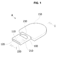
- FIG. 1 is a perspective view of a microcuvette according to one example of the present disclosure
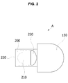
- FIG. 2 is a top view of FIG.1
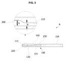
- FIG. 3 is a cross-sectional view taken along the line 'I - I' of FIG. 1 in one embodiment
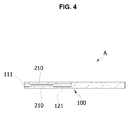
- FIG. 4 is a cross-sectional view taken along the line 'I - I' of FIG. 1 in another embodiment
- FIG. 5 is a perspective view of a microcuvette according to the other example of the present disclosure
- FIG. 6 is a cross-sectional view taken along a line 'II - II' of FIG. 5 in one embodiment
- FIG. 7a and 7b are schematic diagrams each showing one exemplary usage of the present microcuvette.
- the present disclosure relates to a capillary microcuvette
- the present microcuvette (A) includes a body member 100 having two planar plates and a cavity 200 formed within the body member 100.
- a sample or specimen which can be used with the present microcuvette includes, but is not limited to, a fluid biological material such as whole blood, plasma, and serum, urine and a viscous biological material such as feces, expectoration, saliva, and nasal discharge and the like. Viscous materials may be diluted with a suitable liquid such as physiological saline or buffer to introduce the sample to the microcuvette by capillary action.
- the cavity 200 is defined by two inner surfaces 111, 112 of two planar plates 110, 120 of the body member 100. As further described hereinafter, at least one or more inner surfaces have may be flat or inwardly protrude to adjust the gap distance of the cavity at the detection zone 210.
- the outer surface of the plates may be flat and the inner surface may inwardly protrude as needed to adjust the gap distance of the cavity at detection zone 210.
- the body member 100 comprises proximal and distal end portions along a longitudinal axis of the body member 100.
- the capillary inlet 220 which is communicated with the cavity, is formed at one of the end.
- the sample slot 230 which is communicated with the cavity 230, is provided at the other end portion of the body member at which the capillary inlet 220 is not formed.
- the body member or the microcuvette of the present disclosure may further comprise a handle 150 at one end portion of the body member at which the capillary inlet 220 is not formed.
- the cavity 200 is configured to have a width which gradually decreases from a direction of the capillary inlet 220 to the sample slot 230, which facilitates the flow of a sample or specimen loaded by capillary action.
- the capillary inlet 220 is communicated with the cavity along a longitudinal axis of the body member 100.
- the sample slot 230 is formed on one of the two plates 110 or 120 of the body member 100 and communicates with cavity.
- the cavity is extending from the capillary inlet to the sample slot.
- capillary inlet 220 may be configured to have a slant 221 as shown in FIGs. 5 and 6 .
- the slant 221 facilitates an influx of sample loaded and also the sample thus introduced is prevented from being outflowed when the excess sample loaded is removed from the capillary inlet 220.
- sample slot 230 may be configured to have a recessed portion 231.
- the introduction of a specimen such as blood through the capillary inlet 220 generates a flow or a movement of the sample in a direction from the capillary inlet 220 to the sample slot 230, which results in the sample loaded being transported at the detection zone 210.
- a sample or a specimen such as blood is applied at the sample slot 230, a flow or a movement of the sample is generated in a direction from the capillary slot to the capillary inlet 220, which results in the sample being transported at the detection zone 210.
- the convenience in analysis is improved because the sample such as blood may be applied or introduced either through the capillary inlet 220 or the sample slot 230, where in both cases, the sample applied is transported to the detection zone 210, at which the sample is analyzed by measuring the absorbance after illuminating the detection zone 210 with a light with an appropriate wavelength.
- the detection zone 210 is formed at a portion of the cavity 200. In one embodiment, at least one of the inner surfaces 111, 121 of the detection zone 210 inwardly protrudes as shown in FIGs. 3 and 4 .
- the plates (110, 120) or the body member 100 comprising the two plates (110, 120) is made of various materials that may be light transmittable for optical measurements.
- the detection zone may be made of a light transmittable material and the rest of the microcuvette is made of a non-transmittable material.
- the detection zone or the entire microcuvette is made of a light transmittable material
- appropriate materials may be selected by one of the skilled persons in the art considering the types of light illuminated and/or samples.
- polymeric materials such as glass or plastic may be used.
- polystyrene may be used, but is not limited thereto.
- visible lights materials such as polystyrene may be used.
- the gap or gap distance '(a)' of the cavity at detection zone 210 is narrower than the gap '(b)' at the rest of the cavity 200.
- the detection zone 210 is to detect an analyte of interest present in a sample by optical methods using light illumination and it determines a distance of the optical passage.
- the gap '(a)' of the cavity at the detection zone may vary depending on the types of sample analyzed, the types or characteristics of the analyte of interest, or the types or intensity of the light used for illumination.
- the gap '(a)' may be from about 0.05 to about 0.25mm in length, and the light being used for illumination has a wavelength of about 500 to 550 nm.
- the gap is about 0.2 mm.
- the gap is about 0.1 mm.
- the gap of the cavity other than the detection zone may be ranged from about 0.5 mm to about 1.5 mm.
- the difference in the gap distance between the detection zone and the rest of the cavity area prevents generation or trapping of air bubbles in the sample loaded within the detection zone 210.
- the bubbles introduced are removed as the sample applied is spreading out to the detection zone 201 at which the gap becomes narrower than that of the rest of the cavity.
- the accuracy at the measurement or detection level is further improved.
- the detection zone 210 may be formed of various shapes such a polygon or a circle or a simple closed curve, when viewed from the top.
- a sample such as blood may be loaded to the capillary inlet 220 directly from a fingertip as shown in FIG. 7a , or a sample may be loaded using pipette 231 through the sample slot 230, through which the user convenience is improved.
- the capillary microcuvette may be used for measuring not only the amounts of haemoglobins in a sample, but also the amount of other analytes such as glucose, urea, nitrogen and proteins. Not only blood but also other various samples may be used with the present capillary microcuvette.
- the microcuvette of the present invention is used in medical diagnosis/detection fields, but it may also be applied to various other industrial fields where the present microcuvette is applicable.
- A- Capillary microcuvette of the present invention 100- body member 110, 120 - plates 111, 121- Inner surfaces of the plates 150 - handle 200 - cavity 210 - detection zone 220 - capillary inlet 221 - slant 230 - sample slot.
Landscapes
- Health & Medical Sciences (AREA)
- Life Sciences & Earth Sciences (AREA)
- General Health & Medical Sciences (AREA)
- Engineering & Computer Science (AREA)
- Physics & Mathematics (AREA)
- Pathology (AREA)
- Hematology (AREA)
- Biomedical Technology (AREA)
- Chemical & Material Sciences (AREA)
- Biophysics (AREA)
- Molecular Biology (AREA)
- Heart & Thoracic Surgery (AREA)
- Animal Behavior & Ethology (AREA)
- Surgery (AREA)
- Public Health (AREA)
- Veterinary Medicine (AREA)
- Medical Informatics (AREA)
- Analytical Chemistry (AREA)
- Immunology (AREA)
- Biochemistry (AREA)
- General Physics & Mathematics (AREA)
- Clinical Laboratory Science (AREA)
- Dermatology (AREA)
- Dispersion Chemistry (AREA)
- Chemical Kinetics & Catalysis (AREA)
- Manufacturing & Machinery (AREA)
- Urology & Nephrology (AREA)
- Medicinal Chemistry (AREA)
- Ecology (AREA)
- Food Science & Technology (AREA)
- Investigating Or Analysing Biological Materials (AREA)
- Sampling And Sample Adjustment (AREA)
- Optical Measuring Cells (AREA)
- Measurement Of The Respiration, Hearing Ability, Form, And Blood Characteristics Of Living Organisms (AREA)
Applications Claiming Priority (2)
| Application Number | Priority Date | Filing Date | Title |
|---|---|---|---|
| KR1020110080964A KR101215006B1 (ko) | 2011-08-16 | 2011-08-16 | 이중 채취수단을 갖는 모세관 마이크로 큐베트 |
| PCT/KR2012/006465 WO2013025036A2 (ko) | 2011-08-16 | 2012-08-14 | 이중 채취수단을 갖는 모세관 마이크로 큐베트 |
Publications (4)
| Publication Number | Publication Date |
|---|---|
| EP2745779A2 true EP2745779A2 (de) | 2014-06-25 |
| EP2745779A4 EP2745779A4 (de) | 2015-03-04 |
| EP2745779B1 EP2745779B1 (de) | 2016-03-16 |
| EP2745779B8 EP2745779B8 (de) | 2016-08-31 |
Family
ID=47715586
Family Applications (1)
| Application Number | Title | Priority Date | Filing Date |
|---|---|---|---|
| EP12824276.5A Active EP2745779B8 (de) | 2011-08-16 | 2012-08-14 | Kapillar-mikroküvette mit doppeltem auffangmittel |
Country Status (5)
| Country | Link |
|---|---|
| US (1) | US9261455B2 (de) |
| EP (1) | EP2745779B8 (de) |
| KR (1) | KR101215006B1 (de) |
| CN (1) | CN103717133B (de) |
| WO (1) | WO2013025036A2 (de) |
Cited By (1)
| Publication number | Priority date | Publication date | Assignee | Title |
|---|---|---|---|---|
| EP3974809A1 (de) | 2020-09-29 | 2022-03-30 | Bioanalyt GmbH | Mikroküvette |
Families Citing this family (23)
| Publication number | Priority date | Publication date | Assignee | Title |
|---|---|---|---|---|
| EP2892496B1 (de) | 2012-09-06 | 2017-06-28 | Theranos, Inc. | Vorrichtungen zur entnahme von körperflüssigkeitsproben |
| US9636062B2 (en) | 2012-09-06 | 2017-05-02 | Theranos, Inc. | Systems, devices, and methods for bodily fluid sample collection |
| US20140342371A1 (en) * | 2012-12-05 | 2014-11-20 | Theranos, Inc. | Bodily Fluid Sample Collection and Transport |
| US10248765B1 (en) | 2012-12-05 | 2019-04-02 | Theranos Ip Company, Llc | Systems, devices, and methods for bodily fluid sample collection, transport, and handling |
| US9386948B2 (en) | 2012-12-05 | 2016-07-12 | Theranos, Inc. | Systems, devices, and methods for bodily fluid sample transport |
| EP2972184A4 (de) | 2013-03-15 | 2016-11-30 | Theranos Inc | Verfahren und vorrichtungen zur probenentnahme und -trennung |
| US9795929B2 (en) | 2013-03-15 | 2017-10-24 | Theranos, Inc. | Systems, devices, and methods for bodily fluid separation materials |
| KR101519897B1 (ko) * | 2013-11-15 | 2015-05-14 | 바디텍메드 주식회사 | 모세관 구조물을 구비한 측방유동 분석용 카트리지 |
| CN113331832A (zh) | 2014-03-12 | 2021-09-03 | 赛拉诺斯知识产权有限责任公司 | 用于体液样品收集的装置和方法 |
| JP2018509634A (ja) * | 2015-01-14 | 2018-04-05 | フランク・トーマス・ハートレイ | 体液を抜き取る装置及びその方法 |
| FR3033407B1 (fr) * | 2015-03-02 | 2017-03-31 | Avalun | Dispositif de prelevement d'un echantillon liquide par capillarite. |
| WO2016145127A1 (en) | 2015-03-09 | 2016-09-15 | California Institute Of Technology | Mid-infrared hyperspectral spectroscopy systems and methods thereof |
| US10371606B2 (en) | 2015-07-21 | 2019-08-06 | Theraos IP Company, LLC | Bodily fluid sample collection and transport |
| WO2017044888A1 (en) | 2015-09-09 | 2017-03-16 | Theranos, Inc. | Methods and devices for sample collection and sample separation |
| US11857966B1 (en) | 2017-03-15 | 2024-01-02 | Labrador Diagnostics Llc | Methods and devices for sample collection and sample separation |
| US10117615B1 (en) * | 2017-08-01 | 2018-11-06 | Nova Biomedical Corporation | Analyzer cartridge with capillary wiper |
| WO2020163492A1 (en) | 2019-02-06 | 2020-08-13 | California Institute Of Technology | Compact hyperspectral mid-infrared spectrometer |
| CN111912771B (zh) * | 2019-05-09 | 2025-10-21 | 苏州中科苏净生物技术有限公司 | 一种免疫检测联合白细胞计数的同步检测装置及其检测方法 |
| CN111912766B (zh) * | 2019-05-09 | 2025-10-21 | 苏州中科苏净生物技术有限公司 | 免疫检测与细胞分析用组合检测卡及联合检测方法 |
| CN111912770A (zh) * | 2019-05-09 | 2020-11-10 | 磐创精准(北京)生物科技有限公司 | 一种手持式白细胞计数仪及白细胞计数方法 |
| WO2021092579A1 (en) | 2019-11-08 | 2021-05-14 | California Institute Of Technology | Infrared spectrometer having dielectric-polymer-based spectral filter |
| JP7624827B2 (ja) * | 2019-12-10 | 2025-01-31 | 株式会社堀場製作所 | 検体採取具、検体採取具の製造方法、及び測定システム |
| JP7408367B2 (ja) * | 2019-12-10 | 2024-01-05 | 株式会社堀場製作所 | 検体採取具、検体採取具の製造方法、及び測定システム |
Family Cites Families (13)
| Publication number | Priority date | Publication date | Assignee | Title |
|---|---|---|---|---|
| US4696797A (en) * | 1985-04-15 | 1987-09-29 | Environmental Diagnostics, Inc. | Suspension liquid separator |
| JPH04188065A (ja) * | 1990-11-21 | 1992-07-06 | Kyoto Daiichi Kagaku:Kk | 液体試料分析用具および分析方法 |
| JP3382632B2 (ja) * | 1992-03-13 | 2003-03-04 | オリンパス光学工業株式会社 | 生体関連物質の測定方法およびそれに用いる反応容器 |
| US5308775A (en) * | 1992-09-15 | 1994-05-03 | Abbott Laboratories | Assay devices for concurrently detecting an analyte and confirming the test result |
| SE504193C2 (sv) | 1995-04-21 | 1996-12-02 | Hemocue Ab | Kapillär mikrokyvett |
| DE19753850A1 (de) * | 1997-12-04 | 1999-06-10 | Roche Diagnostics Gmbh | Probennahmevorrichtung |
| DE19753849A1 (de) * | 1997-12-04 | 1999-06-10 | Roche Diagnostics Gmbh | Analytisches Testelement mit sich verjüngendem Kapillarkanal |
| US7604775B2 (en) * | 2002-08-12 | 2009-10-20 | Bayer Healthcare Llc | Fluid collecting and monitoring device |
| US7259846B2 (en) | 2005-08-30 | 2007-08-21 | Agilent Technologies, Inc. | Lab in a cuvette |
| DE102006025477B4 (de) * | 2006-05-30 | 2009-01-15 | Ekf - Diagnostic Gmbh | Küvette und Verfahren zu ihrer Herstellung |
| US8115922B2 (en) | 2008-02-29 | 2012-02-14 | Starna Cells, Inc. | Apparatus and method for adapting conventional cuvettes for use in a vertical light beam spectrophotometer |
| KR101147534B1 (ko) * | 2009-06-02 | 2012-05-21 | 주식회사 인포피아 | 시료 채취 및 주입 기구 |
| JP5731516B2 (ja) * | 2009-10-15 | 2015-06-10 | ポステック アカデミー−インダストリー ファンデーション | キュベット |
-
2011
- 2011-08-16 KR KR1020110080964A patent/KR101215006B1/ko active Active
-
2012
- 2012-08-14 EP EP12824276.5A patent/EP2745779B8/de active Active
- 2012-08-14 US US14/238,191 patent/US9261455B2/en active Active
- 2012-08-14 CN CN201280036764.5A patent/CN103717133B/zh active Active
- 2012-08-14 WO PCT/KR2012/006465 patent/WO2013025036A2/ko not_active Ceased
Cited By (2)
| Publication number | Priority date | Publication date | Assignee | Title |
|---|---|---|---|---|
| EP3974809A1 (de) | 2020-09-29 | 2022-03-30 | Bioanalyt GmbH | Mikroküvette |
| WO2022069536A1 (en) | 2020-09-29 | 2022-04-07 | Bioanalyt Gmbh | Microcuvette |
Also Published As
| Publication number | Publication date |
|---|---|
| KR101215006B1 (ko) | 2012-12-24 |
| CN103717133B (zh) | 2015-11-25 |
| CN103717133A (zh) | 2014-04-09 |
| EP2745779A4 (de) | 2015-03-04 |
| EP2745779B1 (de) | 2016-03-16 |
| US9261455B2 (en) | 2016-02-16 |
| US20140219886A1 (en) | 2014-08-07 |
| WO2013025036A2 (ko) | 2013-02-21 |
| EP2745779B8 (de) | 2016-08-31 |
| WO2013025036A3 (ko) | 2013-04-11 |
Similar Documents
| Publication | Publication Date | Title |
|---|---|---|
| US9261455B2 (en) | Capillary microcuvette having double loading means | |
| US12059681B2 (en) | Devices, systems, methods, and kits for receiving a swab | |
| US9678069B2 (en) | Rotatable fluid sample collection device | |
| JP4104921B2 (ja) | 検査器具及びその使用方法 | |
| KR19980018607A (ko) | 중공형 프러스텀 시약 테스트 디바이스 | |
| CN100570332C (zh) | 微片 | |
| WO2013163035A1 (en) | Devices and methods for detecting analyte in bodily fluid | |
| AU2023202958B2 (en) | Fluid collection unit and related devices and methods | |
| US11221324B2 (en) | Portable diagnostic measurement device for determining analytical parameter of body fluid | |
| JP2001245872A (ja) | 補助具 | |
| HK40105452A (en) | Fluid collection unit and related devices and methods | |
| HK40093858A (zh) | 流体收集单元以及相关装置和方法 | |
| HK40029272A (en) | Cartridge for holding reagents, system, kit and swab container | |
| HK1224738A1 (en) | Devices, systems, methods and kits for receiving a swab |
Legal Events
| Date | Code | Title | Description |
|---|---|---|---|
| PUAI | Public reference made under article 153(3) epc to a published international application that has entered the european phase |
Free format text: ORIGINAL CODE: 0009012 |
|
| 17P | Request for examination filed |
Effective date: 20140213 |
|
| AK | Designated contracting states |
Kind code of ref document: A2 Designated state(s): AL AT BE BG CH CY CZ DE DK EE ES FI FR GB GR HR HU IE IS IT LI LT LU LV MC MK MT NL NO PL PT RO RS SE SI SK SM TR |
|
| DAX | Request for extension of the european patent (deleted) | ||
| A4 | Supplementary search report drawn up and despatched |
Effective date: 20150204 |
|
| RIC1 | Information provided on ipc code assigned before grant |
Ipc: A61B 5/15 20060101ALI20150129BHEP Ipc: A61B 10/00 20060101ALI20150129BHEP Ipc: A61B 5/157 20060101AFI20150129BHEP Ipc: B01L 3/00 20060101ALI20150129BHEP |
|
| GRAP | Despatch of communication of intention to grant a patent |
Free format text: ORIGINAL CODE: EPIDOSNIGR1 |
|
| RIC1 | Information provided on ipc code assigned before grant |
Ipc: B01L 3/00 20060101ALI20150904BHEP Ipc: A61B 5/15 20060101ALI20150904BHEP Ipc: A61B 5/157 20060101AFI20150904BHEP Ipc: A61B 10/00 20060101ALI20150904BHEP |
|
| INTG | Intention to grant announced |
Effective date: 20150921 |
|
| GRAS | Grant fee paid |
Free format text: ORIGINAL CODE: EPIDOSNIGR3 |
|
| GRAA | (expected) grant |
Free format text: ORIGINAL CODE: 0009210 |
|
| AK | Designated contracting states |
Kind code of ref document: B1 Designated state(s): AL AT BE BG CH CY CZ DE DK EE ES FI FR GB GR HR HU IE IS IT LI LT LU LV MC MK MT NL NO PL PT RO RS SE SI SK SM TR |
|
| REG | Reference to a national code |
Ref country code: GB Ref legal event code: FG4D |
|
| REG | Reference to a national code |
Ref country code: CH Ref legal event code: EP |
|
| REG | Reference to a national code |
Ref country code: SE Ref legal event code: TRGR |
|
| REG | Reference to a national code |
Ref country code: IE Ref legal event code: FG4D |
|
| REG | Reference to a national code |
Ref country code: AT Ref legal event code: REF Ref document number: 780461 Country of ref document: AT Kind code of ref document: T Effective date: 20160415 |
|
| REG | Reference to a national code |
Ref country code: DE Ref legal event code: R096 Ref document number: 602012015796 Country of ref document: DE |
|
| RAP2 | Party data changed (patent owner data changed or rights of a patent transferred) |
Owner name: BODITECH MED INC. |
|
| REG | Reference to a national code |
Ref country code: NL Ref legal event code: MP Effective date: 20160316 |
|
| REG | Reference to a national code |
Ref country code: LT Ref legal event code: MG4D |
|
| PG25 | Lapsed in a contracting state [announced via postgrant information from national office to epo] |
Ref country code: HR Free format text: LAPSE BECAUSE OF FAILURE TO SUBMIT A TRANSLATION OF THE DESCRIPTION OR TO PAY THE FEE WITHIN THE PRESCRIBED TIME-LIMIT Effective date: 20160316 Ref country code: FI Free format text: LAPSE BECAUSE OF FAILURE TO SUBMIT A TRANSLATION OF THE DESCRIPTION OR TO PAY THE FEE WITHIN THE PRESCRIBED TIME-LIMIT Effective date: 20160316 Ref country code: GR Free format text: LAPSE BECAUSE OF FAILURE TO SUBMIT A TRANSLATION OF THE DESCRIPTION OR TO PAY THE FEE WITHIN THE PRESCRIBED TIME-LIMIT Effective date: 20160617 Ref country code: NO Free format text: LAPSE BECAUSE OF FAILURE TO SUBMIT A TRANSLATION OF THE DESCRIPTION OR TO PAY THE FEE WITHIN THE PRESCRIBED TIME-LIMIT Effective date: 20160616 |
|
| REG | Reference to a national code |
Ref country code: DE Ref legal event code: R082 Ref document number: 602012015796 Country of ref document: DE Representative=s name: TER MEER STEINMEISTER & PARTNER PATENTANWAELTE, DE |
|
| REG | Reference to a national code |
Ref country code: AT Ref legal event code: MK05 Ref document number: 780461 Country of ref document: AT Kind code of ref document: T Effective date: 20160316 |
|
| REG | Reference to a national code |
Ref country code: FR Ref legal event code: PLFP Year of fee payment: 5 |
|
| PG25 | Lapsed in a contracting state [announced via postgrant information from national office to epo] |
Ref country code: NL Free format text: LAPSE BECAUSE OF FAILURE TO SUBMIT A TRANSLATION OF THE DESCRIPTION OR TO PAY THE FEE WITHIN THE PRESCRIBED TIME-LIMIT Effective date: 20160316 Ref country code: LV Free format text: LAPSE BECAUSE OF FAILURE TO SUBMIT A TRANSLATION OF THE DESCRIPTION OR TO PAY THE FEE WITHIN THE PRESCRIBED TIME-LIMIT Effective date: 20160316 Ref country code: RS Free format text: LAPSE BECAUSE OF FAILURE TO SUBMIT A TRANSLATION OF THE DESCRIPTION OR TO PAY THE FEE WITHIN THE PRESCRIBED TIME-LIMIT Effective date: 20160316 Ref country code: LT Free format text: LAPSE BECAUSE OF FAILURE TO SUBMIT A TRANSLATION OF THE DESCRIPTION OR TO PAY THE FEE WITHIN THE PRESCRIBED TIME-LIMIT Effective date: 20160316 |
|
| REG | Reference to a national code |
Ref country code: DE Ref legal event code: R082 Ref document number: 602012015796 Country of ref document: DE Representative=s name: TER MEER STEINMEISTER & PARTNER PATENTANWAELTE, DE |
|
| PG25 | Lapsed in a contracting state [announced via postgrant information from national office to epo] |
Ref country code: PL Free format text: LAPSE BECAUSE OF FAILURE TO SUBMIT A TRANSLATION OF THE DESCRIPTION OR TO PAY THE FEE WITHIN THE PRESCRIBED TIME-LIMIT Effective date: 20160316 Ref country code: IS Free format text: LAPSE BECAUSE OF FAILURE TO SUBMIT A TRANSLATION OF THE DESCRIPTION OR TO PAY THE FEE WITHIN THE PRESCRIBED TIME-LIMIT Effective date: 20160716 Ref country code: EE Free format text: LAPSE BECAUSE OF FAILURE TO SUBMIT A TRANSLATION OF THE DESCRIPTION OR TO PAY THE FEE WITHIN THE PRESCRIBED TIME-LIMIT Effective date: 20160316 |
|
| PG25 | Lapsed in a contracting state [announced via postgrant information from national office to epo] |
Ref country code: CZ Free format text: LAPSE BECAUSE OF FAILURE TO SUBMIT A TRANSLATION OF THE DESCRIPTION OR TO PAY THE FEE WITHIN THE PRESCRIBED TIME-LIMIT Effective date: 20160316 Ref country code: SK Free format text: LAPSE BECAUSE OF FAILURE TO SUBMIT A TRANSLATION OF THE DESCRIPTION OR TO PAY THE FEE WITHIN THE PRESCRIBED TIME-LIMIT Effective date: 20160316 Ref country code: SM Free format text: LAPSE BECAUSE OF FAILURE TO SUBMIT A TRANSLATION OF THE DESCRIPTION OR TO PAY THE FEE WITHIN THE PRESCRIBED TIME-LIMIT Effective date: 20160316 Ref country code: PT Free format text: LAPSE BECAUSE OF FAILURE TO SUBMIT A TRANSLATION OF THE DESCRIPTION OR TO PAY THE FEE WITHIN THE PRESCRIBED TIME-LIMIT Effective date: 20160718 Ref country code: RO Free format text: LAPSE BECAUSE OF FAILURE TO SUBMIT A TRANSLATION OF THE DESCRIPTION OR TO PAY THE FEE WITHIN THE PRESCRIBED TIME-LIMIT Effective date: 20160316 Ref country code: AT Free format text: LAPSE BECAUSE OF FAILURE TO SUBMIT A TRANSLATION OF THE DESCRIPTION OR TO PAY THE FEE WITHIN THE PRESCRIBED TIME-LIMIT Effective date: 20160316 Ref country code: ES Free format text: LAPSE BECAUSE OF FAILURE TO SUBMIT A TRANSLATION OF THE DESCRIPTION OR TO PAY THE FEE WITHIN THE PRESCRIBED TIME-LIMIT Effective date: 20160316 |
|
| REG | Reference to a national code |
Ref country code: DE Ref legal event code: R097 Ref document number: 602012015796 Country of ref document: DE |
|
| PG25 | Lapsed in a contracting state [announced via postgrant information from national office to epo] |
Ref country code: BE Free format text: LAPSE BECAUSE OF FAILURE TO SUBMIT A TRANSLATION OF THE DESCRIPTION OR TO PAY THE FEE WITHIN THE PRESCRIBED TIME-LIMIT Effective date: 20160316 |
|
| PLBE | No opposition filed within time limit |
Free format text: ORIGINAL CODE: 0009261 |
|
| STAA | Information on the status of an ep patent application or granted ep patent |
Free format text: STATUS: NO OPPOSITION FILED WITHIN TIME LIMIT |
|
| PG25 | Lapsed in a contracting state [announced via postgrant information from national office to epo] |
Ref country code: DK Free format text: LAPSE BECAUSE OF FAILURE TO SUBMIT A TRANSLATION OF THE DESCRIPTION OR TO PAY THE FEE WITHIN THE PRESCRIBED TIME-LIMIT Effective date: 20160316 |
|
| 26N | No opposition filed |
Effective date: 20161219 |
|
| PG25 | Lapsed in a contracting state [announced via postgrant information from national office to epo] |
Ref country code: BG Free format text: LAPSE BECAUSE OF FAILURE TO SUBMIT A TRANSLATION OF THE DESCRIPTION OR TO PAY THE FEE WITHIN THE PRESCRIBED TIME-LIMIT Effective date: 20160616 |
|
| PG25 | Lapsed in a contracting state [announced via postgrant information from national office to epo] |
Ref country code: MC Free format text: LAPSE BECAUSE OF FAILURE TO SUBMIT A TRANSLATION OF THE DESCRIPTION OR TO PAY THE FEE WITHIN THE PRESCRIBED TIME-LIMIT Effective date: 20160316 |
|
| REG | Reference to a national code |
Ref country code: CH Ref legal event code: PL |
|
| GBPC | Gb: european patent ceased through non-payment of renewal fee |
Effective date: 20160814 |
|
| PG25 | Lapsed in a contracting state [announced via postgrant information from national office to epo] |
Ref country code: LI Free format text: LAPSE BECAUSE OF NON-PAYMENT OF DUE FEES Effective date: 20160831 Ref country code: CH Free format text: LAPSE BECAUSE OF NON-PAYMENT OF DUE FEES Effective date: 20160831 |
|
| PG25 | Lapsed in a contracting state [announced via postgrant information from national office to epo] |
Ref country code: SI Free format text: LAPSE BECAUSE OF FAILURE TO SUBMIT A TRANSLATION OF THE DESCRIPTION OR TO PAY THE FEE WITHIN THE PRESCRIBED TIME-LIMIT Effective date: 20160316 |
|
| REG | Reference to a national code |
Ref country code: IE Ref legal event code: MM4A |
|
| PG25 | Lapsed in a contracting state [announced via postgrant information from national office to epo] |
Ref country code: GB Free format text: LAPSE BECAUSE OF NON-PAYMENT OF DUE FEES Effective date: 20160814 Ref country code: IE Free format text: LAPSE BECAUSE OF NON-PAYMENT OF DUE FEES Effective date: 20160814 |
|
| REG | Reference to a national code |
Ref country code: FR Ref legal event code: PLFP Year of fee payment: 6 |
|
| PG25 | Lapsed in a contracting state [announced via postgrant information from national office to epo] |
Ref country code: LU Free format text: LAPSE BECAUSE OF NON-PAYMENT OF DUE FEES Effective date: 20160814 |
|
| PG25 | Lapsed in a contracting state [announced via postgrant information from national office to epo] |
Ref country code: HU Free format text: LAPSE BECAUSE OF FAILURE TO SUBMIT A TRANSLATION OF THE DESCRIPTION OR TO PAY THE FEE WITHIN THE PRESCRIBED TIME-LIMIT; INVALID AB INITIO Effective date: 20120814 Ref country code: CY Free format text: LAPSE BECAUSE OF FAILURE TO SUBMIT A TRANSLATION OF THE DESCRIPTION OR TO PAY THE FEE WITHIN THE PRESCRIBED TIME-LIMIT Effective date: 20160316 |
|
| PG25 | Lapsed in a contracting state [announced via postgrant information from national office to epo] |
Ref country code: MT Free format text: LAPSE BECAUSE OF NON-PAYMENT OF DUE FEES Effective date: 20160831 Ref country code: MK Free format text: LAPSE BECAUSE OF FAILURE TO SUBMIT A TRANSLATION OF THE DESCRIPTION OR TO PAY THE FEE WITHIN THE PRESCRIBED TIME-LIMIT Effective date: 20160316 |
|
| REG | Reference to a national code |
Ref country code: FR Ref legal event code: PLFP Year of fee payment: 7 |
|
| PG25 | Lapsed in a contracting state [announced via postgrant information from national office to epo] |
Ref country code: AL Free format text: LAPSE BECAUSE OF FAILURE TO SUBMIT A TRANSLATION OF THE DESCRIPTION OR TO PAY THE FEE WITHIN THE PRESCRIBED TIME-LIMIT Effective date: 20160316 Ref country code: TR Free format text: LAPSE BECAUSE OF FAILURE TO SUBMIT A TRANSLATION OF THE DESCRIPTION OR TO PAY THE FEE WITHIN THE PRESCRIBED TIME-LIMIT Effective date: 20160316 |
|
| PGFP | Annual fee paid to national office [announced via postgrant information from national office to epo] |
Ref country code: DE Payment date: 20250827 Year of fee payment: 14 |
|
| PGFP | Annual fee paid to national office [announced via postgrant information from national office to epo] |
Ref country code: IT Payment date: 20250829 Year of fee payment: 14 |
|
| PGFP | Annual fee paid to national office [announced via postgrant information from national office to epo] |
Ref country code: FR Payment date: 20250821 Year of fee payment: 14 |
|
| PGFP | Annual fee paid to national office [announced via postgrant information from national office to epo] |
Ref country code: SE Payment date: 20250821 Year of fee payment: 14 |