EP2745812A1 - Contraintes de diamètre repositionnable - Google Patents
Contraintes de diamètre repositionnable Download PDFInfo
- Publication number
- EP2745812A1 EP2745812A1 EP13275322.9A EP13275322A EP2745812A1 EP 2745812 A1 EP2745812 A1 EP 2745812A1 EP 13275322 A EP13275322 A EP 13275322A EP 2745812 A1 EP2745812 A1 EP 2745812A1
- Authority
- EP
- European Patent Office
- Prior art keywords
- graft
- cannula
- suture
- lumen
- attachment member
- Prior art date
- Legal status (The legal status is an assumption and is not a legal conclusion. Google has not performed a legal analysis and makes no representation as to the accuracy of the status listed.)
- Granted
Links
- CTOUNSPKBGUFNA-UHFFFAOYSA-N CCCCC(CC)CCN Chemical compound CCCCC(CC)CCN CTOUNSPKBGUFNA-UHFFFAOYSA-N 0.000 description 1
Images

Classifications
-
- A—HUMAN NECESSITIES
- A61—MEDICAL OR VETERINARY SCIENCE; HYGIENE
- A61F—FILTERS IMPLANTABLE INTO BLOOD VESSELS; PROSTHESES; DEVICES PROVIDING PATENCY TO, OR PREVENTING COLLAPSING OF, TUBULAR STRUCTURES OF THE BODY, e.g. STENTS; ORTHOPAEDIC, NURSING OR CONTRACEPTIVE DEVICES; FOMENTATION; TREATMENT OR PROTECTION OF EYES OR EARS; BANDAGES, DRESSINGS OR ABSORBENT PADS; FIRST-AID KITS
- A61F2/00—Filters implantable into blood vessels; Prostheses, i.e. artificial substitutes or replacements for parts of the body; Appliances for connecting them with the body; Devices providing patency to, or preventing collapsing of, tubular structures of the body, e.g. stents
- A61F2/95—Instruments specially adapted for placement or removal of stents or stent-grafts
-
- A—HUMAN NECESSITIES
- A61—MEDICAL OR VETERINARY SCIENCE; HYGIENE
- A61F—FILTERS IMPLANTABLE INTO BLOOD VESSELS; PROSTHESES; DEVICES PROVIDING PATENCY TO, OR PREVENTING COLLAPSING OF, TUBULAR STRUCTURES OF THE BODY, e.g. STENTS; ORTHOPAEDIC, NURSING OR CONTRACEPTIVE DEVICES; FOMENTATION; TREATMENT OR PROTECTION OF EYES OR EARS; BANDAGES, DRESSINGS OR ABSORBENT PADS; FIRST-AID KITS
- A61F2/00—Filters implantable into blood vessels; Prostheses, i.e. artificial substitutes or replacements for parts of the body; Appliances for connecting them with the body; Devices providing patency to, or preventing collapsing of, tubular structures of the body, e.g. stents
- A61F2/02—Prostheses implantable into the body
- A61F2/04—Hollow or tubular parts of organs, e.g. bladders, tracheae, bronchi or bile ducts
- A61F2/06—Blood vessels
- A61F2/07—Stent-grafts
-
- A—HUMAN NECESSITIES
- A61—MEDICAL OR VETERINARY SCIENCE; HYGIENE
- A61F—FILTERS IMPLANTABLE INTO BLOOD VESSELS; PROSTHESES; DEVICES PROVIDING PATENCY TO, OR PREVENTING COLLAPSING OF, TUBULAR STRUCTURES OF THE BODY, e.g. STENTS; ORTHOPAEDIC, NURSING OR CONTRACEPTIVE DEVICES; FOMENTATION; TREATMENT OR PROTECTION OF EYES OR EARS; BANDAGES, DRESSINGS OR ABSORBENT PADS; FIRST-AID KITS
- A61F2/00—Filters implantable into blood vessels; Prostheses, i.e. artificial substitutes or replacements for parts of the body; Appliances for connecting them with the body; Devices providing patency to, or preventing collapsing of, tubular structures of the body, e.g. stents
- A61F2/02—Prostheses implantable into the body
- A61F2/04—Hollow or tubular parts of organs, e.g. bladders, tracheae, bronchi or bile ducts
- A61F2/06—Blood vessels
- A61F2/07—Stent-grafts
- A61F2002/075—Stent-grafts the stent being loosely attached to the graft material, e.g. by stitching
-
- A—HUMAN NECESSITIES
- A61—MEDICAL OR VETERINARY SCIENCE; HYGIENE
- A61F—FILTERS IMPLANTABLE INTO BLOOD VESSELS; PROSTHESES; DEVICES PROVIDING PATENCY TO, OR PREVENTING COLLAPSING OF, TUBULAR STRUCTURES OF THE BODY, e.g. STENTS; ORTHOPAEDIC, NURSING OR CONTRACEPTIVE DEVICES; FOMENTATION; TREATMENT OR PROTECTION OF EYES OR EARS; BANDAGES, DRESSINGS OR ABSORBENT PADS; FIRST-AID KITS
- A61F2/00—Filters implantable into blood vessels; Prostheses, i.e. artificial substitutes or replacements for parts of the body; Appliances for connecting them with the body; Devices providing patency to, or preventing collapsing of, tubular structures of the body, e.g. stents
- A61F2/95—Instruments specially adapted for placement or removal of stents or stent-grafts
- A61F2002/9505—Instruments specially adapted for placement or removal of stents or stent-grafts having retaining means other than an outer sleeve, e.g. male-female connector between stent and instrument
- A61F2002/9511—Instruments specially adapted for placement or removal of stents or stent-grafts having retaining means other than an outer sleeve, e.g. male-female connector between stent and instrument the retaining means being filaments or wires
-
- A—HUMAN NECESSITIES
- A61—MEDICAL OR VETERINARY SCIENCE; HYGIENE
- A61F—FILTERS IMPLANTABLE INTO BLOOD VESSELS; PROSTHESES; DEVICES PROVIDING PATENCY TO, OR PREVENTING COLLAPSING OF, TUBULAR STRUCTURES OF THE BODY, e.g. STENTS; ORTHOPAEDIC, NURSING OR CONTRACEPTIVE DEVICES; FOMENTATION; TREATMENT OR PROTECTION OF EYES OR EARS; BANDAGES, DRESSINGS OR ABSORBENT PADS; FIRST-AID KITS
- A61F2/00—Filters implantable into blood vessels; Prostheses, i.e. artificial substitutes or replacements for parts of the body; Appliances for connecting them with the body; Devices providing patency to, or preventing collapsing of, tubular structures of the body, e.g. stents
- A61F2/95—Instruments specially adapted for placement or removal of stents or stent-grafts
- A61F2002/9534—Instruments specially adapted for placement or removal of stents or stent-grafts for repositioning of stents
-
- A—HUMAN NECESSITIES
- A61—MEDICAL OR VETERINARY SCIENCE; HYGIENE
- A61F—FILTERS IMPLANTABLE INTO BLOOD VESSELS; PROSTHESES; DEVICES PROVIDING PATENCY TO, OR PREVENTING COLLAPSING OF, TUBULAR STRUCTURES OF THE BODY, e.g. STENTS; ORTHOPAEDIC, NURSING OR CONTRACEPTIVE DEVICES; FOMENTATION; TREATMENT OR PROTECTION OF EYES OR EARS; BANDAGES, DRESSINGS OR ABSORBENT PADS; FIRST-AID KITS
- A61F2250/00—Special features of prostheses classified in groups A61F2/00 - A61F2/26 or A61F2/82 or A61F9/00 or A61F11/00 or subgroups thereof
- A61F2250/0004—Special features of prostheses classified in groups A61F2/00 - A61F2/26 or A61F2/82 or A61F9/00 or A61F11/00 or subgroups thereof adjustable
- A61F2250/001—Special features of prostheses classified in groups A61F2/00 - A61F2/26 or A61F2/82 or A61F9/00 or A61F11/00 or subgroups thereof adjustable for adjusting a diameter
Definitions
- the present invention relates to as system for deploying an endoluminal prosthesis, in the preferred embodiments generally to a delivery system for an endoluminal prosthesis having an expandable graft.
- Stent grafts to treat aneurysms or similar defects is common in the medical field. Stent grafts are deployed by accessing a vasculature with a small incision in the skin and guiding a delivery system to the target area. This intraluminal delivery is less invasive and generally preferred over more intrusive forms of surgery.
- the stent grant can be placed against the vessel wall in the area of the defect to close off the defect and provide patent fluid flow through the area of the defect, thereby allowing the defect to heal itself while limiting or substantially preventing blood loss through the vessel wall.
- Methods for delivering a stent graft are well known in the art, and involve guiding the stent graft over a guide wire or similar structure until the graft reaches the target location.
- the stent graft including a cannula therein, is in a compressed state with a diameter that is smaller than the diameter of the graft in the deployed state. The smaller diameter allows the graft to be delivered while limiting the trauma to the patient, with the graft typically delivered through the use of a catheter, as is known in the art.
- the catheter can be withdrawn back along the guide wire toward the surgeon, leaving the graft in place.
- the stent is then released from its compressed state by typically withdrawing a trigger wire in the case of a self-expanding stent. After withdrawing the trigger wire, the self-expanding stent will expand outwardly into contact with the luminal wall.
- the stent can be expanded by using a balloon therein, which can be inflated to force the diameter of the stent outward and into engagement with the luminal wall.
- the stent is generally limited in its ability to reduce the diameter. This is because the purpose of the stent is to provide outward pressure on the luminal wall to remain in place and treat the vascular defect.
- surgeon may desire the ability to reduce the diameter of the stent after it has at least partially expanded, such as an instance where the stent needs to be repositioned along the vasculature, either due to initial misplacement or discovery of an additional defect adjacent the target site.
- the surgeon may be required to deliver an additional stent graft to the same target area to sufficiently treat the defect, adding time and material to the procedure and resulting in increased trauma to the patient.
- the present invention seeks to provide an improved prosthesis deployment system.
- the preferred embodiments disclosed herein can provide a stent graft that can be at least partially expanded and subsequently compressed to allow the surgeon to reposition the stent graft after initial expansion.
- a system for deploying an endoluminal prosthesis comprising: a graft comprising biocompatible material having at least one lumen extending therethrough; a rotatable cannula extending at least partially through the graft lumen; a suture having a first portion and a second portion, the first portion being coupled to the rotatable cannula within the graft lumen and the second portion being coupled to the graft, wherein the lengths of the first and second portions adjust in response to rotation of the rotatable cannula to vary the diameter of the graft.
- the graft has a first diameter in response to rotation of the cannula in a first direction, the graft has a second diameter larger than the first diameter in response to additional rotation of the cannula in the first direction, and the graft has a third diameter less than the second diameter in response to rotation of the cannula in a direction opposite the first direction.
- the suture is at least partially wound around the cannula within the graft lumen.
- the graft may comprise a plurality of openings therethrough, the suture first portion is at least partially threaded through the plurality of openings, and alternating portions of the suture first portion are disposed inside and outside of the graft.
- the suture includes a loop portion at the first end thereof, the cannula has an attachment member thereof, and the loop portion is coupled to the attachment member.
- the attachment member comprises a hook protruding radially from the cannula.
- the attachment member can comprise a wire extending longitudinally along the cannula.
- the cannula may have a tubular body with a lumen extending therethrough and first and second longitudinally spaced openings in the body, the wire extends through the lumen, through the first opening, and through second opening, an intermediate portion of the wire is disposed outside the cannula, and the intermediate portion extends through the suture loop.
- a method for delivering an endoluminal prosthesis including the steps of: locating, within a patient's body, an endoluminal prosthesis having a graft comprising biocompatible material having at least one lumen extending therethrough, wherein a cannula extends at least partially through the graft lumen and a suture is at least partially wound about the cannula and at least partially mounted about a perimeter of the graft; rotating the cannula in a first direction; in response to rotating the cannula in the first direction, unwinding a portion of the suture; expanding the graft outwardly; rotating the cannula in a second direction that is opposite the first direction; in response to rotating the cannula in the second direction, winding a portion of the suture about the cannula; and reducing the diameter of the graft.
- the method can include delivering an endoluminal prosthesis with a system according to other aspects of the invention.
- the method may include the step of rotating the cannula in the first direction and releasing the inner end of the suture from the hook.
- the method preferably comprises the step of withdrawing the wire away from the suture and out of engagement with the loop portion.
- the graft may include a plurality of laterally spaced openings in the graft, the suture extending through the openings in an alternating fashion, a first portion of the suture extending about the graft is outside the graft, and a second portion of the suture extending about the graft is inside the graft.
- the graft may include a plurality of laterally spaced openings in the graft, the suture extending about the graft through the openings in an alternating fashion, a first portion of the suture extending about the graft is outside the graft, and a second portion of the suture extending about the graft is inside the graft.
- the cannula may include an attachment member, wherein an inner end of the suture is releasably mounted to the attachment member.
- the inner end of the suture includes a loop portion and the attachment member extends through the loop portion.
- the attachment member may comprise a hook fixedly mounted to the cannula.
- the attachment member comprises a wire extending along the cannula and through the loop portion.
- the cannula includes a lumen extending therealong, the cannula includes a pair of longitudinally aligned openings through a surface of the cannula, and the wire extends within the cannula lumen through one of the openings to the outside of the cannula and through the other opening to the cannula lumen, an intermediate portion of the wire is outside the cannula, and the intermediate portion extends through the suture loop.
- a system for deploying an endoluminal prosthesis comprises: a graft comprising biocompatible material having at least one lumen extending therethrough; a rotatable cannula extending at least partially through the graft lumen; and a suture having a first portion and a second portion, the first portion being wound around the rotatable cannula within the graft lumen and the second portion extending along the perimeter of the graft, wherein the lengths of the first and second portions adjust in response to rotation of the cannula.
- the system may further comprise a stent coupled to the graft.
- the stent may be a self-expanding stent.
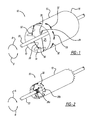
- Figure 1 illustrates a system 10 for delivering an endoluminal prosthesis or tubular graft 12, which can be made from any of the currently available graft materials or other biocompatible materials known in the art.
- the graft 12 preferably has a compressed diameter in the range of 5-8 mm, and an expanded diameter in the range of 20-46 mm.
- the graft 12 is shown in an expanded state in Figure 1 , but it will be appreciated that the diameter can decrease, as further described below.
- the above listed dimensions can vary depending on the patient or the location in the vasculature where the graft 12 is to be deployed.
- the system 10 includes a stent 14 coupled to the graft 12 and having an expandable structure known in the art.
- a stent 14 structure can be found in United States Patent Application No. 12/945,097, filed November 12, 2010 , which is hereby incorporated by reference in its entirety.
- the stent 14 can be either self-expanding, where the stent 14 can be compressed and will spring out in response to releasing the compressing force, or balloon expandable, where a balloon (not shown) can be inflated within the stent 14 to expand the stent 14 outward to an expanded state.
- the stent 14 can be in the form of one or more stent rings (not shown) disposed on either the inside of the graft 12 or the outside of the graft 12.
- a portion of the stent rings can be bare stents that extend beyond one or both ends of the graft 12, with the bare stents having rounded apices.
- the stent rings can be conventional zigzag stent rings with pointed apices, or they can have rounded apices. Alternatively, the stent rings could have other suitable stent ring designs.
- the stent rings are preferably sutured to the graft 12 but can also be connected to the graft 12 by any other suitable means.
- the stent 14 can also be in the form of a unitary self-expanding structure. These types of stent 14 structure and pre-loaded forces are well known in the art and will not be discussed in further detail. In both structure types, the stent 14 can be compressed or expanded in response to sufficient compression or expansion forces acting thereon. For purposes of discussion, when referring to expansion generally, either self-expansion or balloon expansion methods can be used.
- the graft 12 includes a distal end 16, a proximal end 18, and a lumen 20 extending therebetween.
- the system 10 may also include a cannula 22 extending generally along a longitudinal axis of the graft 12 and at least partially through the lumen 20.
- the cannula 22 can have a generally elongated shape with a relatively small diameter for facilitating insertion into a patient's vasculature.
- the cannula 22 has a generally a circular cross-section, however other elongate shapes could also be used, such as a shape having a generally square cross-section.
- the cannula 22 can have a generally solid construction, or could have a hollow tubular form.
- the cannula 22 can include an attachment member 24 fixedly mounted to an outer surface of the cannula 22. The various types of attachment members 24 will be further described below.
- the system 10 also includes a thread or suture 26 that is coupled to both the attachment member 24 of the cannula 22 and the graft 12. More specifically, an inner end 28 of the suture 26 is releasably mounted to the attachment member 24, and an outer end 30 is mounted to the graft 12.
- the graft 12 includes a plurality of openings 32 through the side of the graft 12.
- the openings 32 are generally evenly spaced, in one embodiment, about the perimeter of the graft 12, and are generally aligned along a plane that is transverse to the longitudinal axis of the graft 12.
- the openings 32 could be spaced apart in a non-uniform manner or along a plane at an oblique angle to the longitudinal axis of the graft 12.
- the suture 26 can be threaded through the openings 32 in an alternating fashion, so that the suture 26 extends from the lumen 20 of the graft 12, through one of the openings 32, and to the outside of the graft 12.
- the suture 26 will then extend about the perimeter of the graft 12 toward the opening 32 adjacent the opening 30 through which the suture 26 extended, and then pass through this opening 32 back into the lumen 20. This threading will continue about the graft 12, so that the suture 26 alternates between extending about the perimeter of the graft 12 within the lumen 20 and extending about the perimeter on the outside of the graft 12 in a generally serpentine path. When the suture 26 reaches the final unthreaded opening 32, the suture 26 will extend through that opening 32, where it is then mounted to the graft 12.
- the threading pattern described above can be altered to suit the needs of the user.
- the threading could continue through the openings 32 so that each opening 32 is threaded twice.
- the number of openings 32 is at least six for effective radial compression of the graft 12 as will be explained below.
- the cannula 22, having the attachment member 24 fixedly mounted thereto is rotatable within the graft lumen 20 relative to the graft 12.
- the rotation of the cannula 22 can be controlled by the surgeon outside of the patient's body, along with the various other surgeon controlled aspects of the catheter insertion and retraction known in the art.
- the cannula 22 can be rotated in both a clockwise direction A and counterclockwise direction B. It will be appreciated that the terms clockwise and counterclockwise are intended to describe rotation in opposite rotary directions, and the following rotational descriptions are not dependent on any particular point of view.
- the graft 12 can be radially compressed by rotating the cannula 22 in the clockwise direction A.
- the rotation of the cannula 22 relative to the graft 12 will cause the suture 26 to be wrapped around the perimeter of the cannula 22.
- the suture 26 will have both a wrapped portion 26a and a free portion 26b.
- the wrapped portion 26a will increase and the free portion 26b will decrease.
- the suture 26 is threaded through the openings 32 in the graft 12, the shortening of the free portion 26b due to the wrapping will cause the diameter of the graft 12 to decrease.
- the graft 12 material will generally fold over itself in an accordion fashion.
- the rotation of the cannula 22 can continue until the graft 12 is compressed to a desired diameter.
- the rotation of the cannula 22 can be in addition to traditional techniques for compressing a stent graft.
- the graft 12 can expand if the cannula 22 is rotated in the opposite, counter-clockwise direction B.
- Rotating the cannula 22 in the counter-clockwise direction B allows the free portion 26b to increase, which will allow the stent graft 12 to expand, either by self-expanding or by forcing the stent 14 and graft 12 outward by balloon inflation.
- the cannula 22 can terminate within the lumen 20 of the graft 12 so that the balloon (not shown) can be passed through the cannula 22 or other delivery tube so that it can be inflated within the lumen 20 of the graft 12 to effect the radial expansion. Additionally or alternatively, prior to insertion into the patient, the graft 12 can be expanded manually along with the counterclockwise rotation. Of course, if the cannula 22 has not been rotated to wind the suture 26, the cannula 22 does not need to be rotated to unwind the suture 26.
- the suture 26 is mounted at its inner end 26a to the cannula 22, which allows the cannula 22 to wind and unwind the suture 26 depending on the direction of rotation.
- the inner end 26a of the suture 26 can also be releasable from the attachment member 24 of the cannula 22 in the event that further winding to compress the graft 12 is unnecessary or not desired. An example of such a situation would be when the graft 12 has been located within the vasculature to the satisfaction of the surgeon where further repositioning is no longer desired.
- the manner of releasing the suture 26 from the cannula 22 depends on the structure of the attachment member 24, which will be further described below.
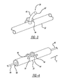
- the attachment member 24 is a hook 40 having a generally rigid and curved form.
- the hook 40 includes a free end 42 that is generally pointed in the direction of rotation corresponding to the rotational direction for winding the suture 26.
- the inner end 26a of the suture can include a loop 44 that the hook 40 extends through, maintaining the connection while the cannula 22 rotates.
- the curved shape of the hook 40 will cam across the loop 44 at the inner end 26a of the suture 26, causing the suture 26 to release from the cannula 22.
- further rotation of the cannula 22 will generally not result in additional winding of the suture 26 and the graft 12 will generally not undergo any additional diameter expansion.
- the graft 12 may expand slightly further when the suture 26 is released because the cannula is no longer limiting the graft 12 from expanding.
- the attachment member 24 can be in the form of a trigger wire 46 that extends through the loop 44 at the inner end 26a of the suture 26. More specifically, the trigger wire 46 can extend through a lumen 48 of the cannula 22.
- the cannula 22 can include a pair of longitudinally aligned openings 50 therein, where the trigger wire 46 can extend from the lumen 48, through the opening 50 to the outside of the cannula 22.
- the trigger wire 46 can then pass through the loop 44 of the suture 26 and through the adjacent opening 50 back into the lumen 48.
- the cannula 22 can be rotated to wind or unwind of the suture 26 as described above.
- the trigger wire 46 can be withdrawn in the direction C, thereby releasing the loop 44 of the suture 26. After the release of the loop 44, further rotation of the cannula 22 will generally not result in further adjustment of the diameter of the graft 12.
- the trigger wire 46 has the advantage of having a low radial profile without any risk of getting caught in the graft material.
- the hook 40 does not require an additional externally controlled element. Which version is preferred depends on the individual situation and on the available radial space.
- delivery of an endoluminal prosthesis can be performed using minimally invasive techniques, whereby a small incision is made in a patient's skin for allowing the insertion of medical devices into the patient's body.
- a guide wire 58 is inserted into the patient and guided generally toward and to the target treatment site in the body.
- the guide wire 58 can be advanced through a patient's vasculature toward and to, for example, the ascending or descending aorta to treat an aortic aneurysm or other defect.
- the graft 12 described above can be compressed into a delivery state, with the cannula 22 rotated to wind the suture 26 therearound so that the stent graft 12 has a reduced diameter.
- the reduced diameter graft 12 can be inserted into a catheter 60 or similar tubular intravenous delivery device.
- the catheter 60 having the stent graft 12 therein can then be threaded over the guide wire 58 as known in the art for translation along the guide wire 58 into the patient's body and ultimately to the target site.
- the graft 12 can be attached at its proximal and distal ends to the catheter 60 via attachments (not shown) that hold the rotary position of the graft in a generally fixed position relative to the catheter 60.
- the attachments could be released using a trigger wire (not shown) or other known method.
- catheter 60 can also include a sheath portion (not shown) that can assist in constraining the diameter of the graft 12 during delivery and be withdrawn similar to the catheter 60, which is described below.
- the catheter 60 is advanced over the guide wire 58 toward the target site using known procedures. Once the catheter 60 has arrived at the target site, the catheter 60 can be withdrawn, exposing the graft 12 to the vasculature.
- the graft 12 will remain in its compressed condition, even if it is a self-expanding type, because the suture 26 has been wound around the cannula 22, which can remain in place after the catheter 60 is withdrawn.
- the cannula 22 can be rotated to allow the suture 26 to unwind.
- the stent graft will be allowed to expand, either due to the built up potential energy in the self-expanding style, or through balloon expansion. The surgeon can monitor the positioning of the graft 12 during its expansion.
- the graft 12 can expand to engage the anatomical wall 70 at the location of the anatomical defect 72 to allow for blood to flow through the graft 12 and to allow for the defect to heal itself, if possible.
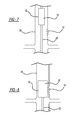
- the surgeon can determine whether the graft 12 is in the proper location after at least partial expansion. If the surgeon wishes to re-position the graft 12, the surgeon can rotate the cannula 22 in the opposite direction to wind the suture 26, which causes the diameter of the stent graft 12 to become reduced ( Figure 7 ), allowing for the stent graft 12 to be moved to a different location. The graft 12 will remain at its reduced diameter until the surgeon wishes to allow it to expand again. To allow the graft 12 to expand again, the cannula 22 can be rotated to allow the suture to unwind and the stent 10 can expand ( Figure 8 ).
- This process of alternating expansion and compression can be repeated multiple times until the surgeon is satisfied with the location of the expanded stent 10. Until the suture 26 is released, the surgeon has the ability to repeatedly wind and unwind the suture 26 to compress and expand the graft 12.
- the surgeon can release the suture from the cannula 22, as described above, depending on the attachment member 24 used to secure the suture 26 to the cannula 22. If the attachment member 24 is in the form of the hook 40, the surgeon can rotate the cannula 22 in the direction to unwind the suture 26 and continue rotating the cannula 22 so that the curved shape of the hook 40 cams along the loop 44 of the suture, causing the hook 40 to retract out of the loop 44 and freeing the suture 26 from the cannula 22.
- the attachment member 24 is in the form of a trigger wire 46
- the surgeon can withdraw the trigger wire 46 away from the graft 12, causing the trigger wire 46 to be pulled through and out of engagement with the loop 44 of the suture 26.
- the cannula 22 can be withdrawn from the graft 12, leaving the graft 12 in place in the patient's body for treating the anatomical defect 72.
- the surgeon can further remove other elements related to the delivery of the graft 12, such as the guide wire 58, in a manner known in the art.
Landscapes
- Health & Medical Sciences (AREA)
- Engineering & Computer Science (AREA)
- Biomedical Technology (AREA)
- Cardiology (AREA)
- Oral & Maxillofacial Surgery (AREA)
- Transplantation (AREA)
- Heart & Thoracic Surgery (AREA)
- Vascular Medicine (AREA)
- Life Sciences & Earth Sciences (AREA)
- Animal Behavior & Ethology (AREA)
- General Health & Medical Sciences (AREA)
- Public Health (AREA)
- Veterinary Medicine (AREA)
- Gastroenterology & Hepatology (AREA)
- Pulmonology (AREA)
- Prostheses (AREA)
Applications Claiming Priority (1)
| Application Number | Priority Date | Filing Date | Title |
|---|---|---|---|
| US201261739240P | 2012-12-19 | 2012-12-19 |
Publications (2)
| Publication Number | Publication Date |
|---|---|
| EP2745812A1 true EP2745812A1 (fr) | 2014-06-25 |
| EP2745812B1 EP2745812B1 (fr) | 2017-01-18 |
Family
ID=49916942
Family Applications (1)
| Application Number | Title | Priority Date | Filing Date |
|---|---|---|---|
| EP13275322.9A Active EP2745812B1 (fr) | 2012-12-19 | 2013-12-18 | Contraintes de diamètre repositionnable |
Country Status (2)
| Country | Link |
|---|---|
| US (1) | US9498361B2 (fr) |
| EP (1) | EP2745812B1 (fr) |
Cited By (17)
| Publication number | Priority date | Publication date | Assignee | Title |
|---|---|---|---|---|
| WO2018027215A1 (fr) * | 2016-08-05 | 2018-02-08 | W. L. Gore & Associates, Inc. | Lumière de contrainte pour dispositif médical intégré. |
| WO2018156854A1 (fr) * | 2017-02-24 | 2018-08-30 | Bolton Medical, Inc. | Système de pose d'endoprothèse à ajustement radial |
| CN109640883A (zh) * | 2016-08-16 | 2019-04-16 | 美敦力瓦斯科尔勒公司 | 减少支架移植物内漏的带涂层缝合线 |
| CN109843226A (zh) * | 2017-02-24 | 2019-06-04 | 波顿医疗公司 | 用于径向收缩支架移植物的递送系统和使用方法 |
| EP3570781A1 (fr) * | 2017-01-20 | 2019-11-27 | Medtronic Vascular Inc. | Prothèse de valvule ayant un manchon extensible radialement intégré sur cette-dernière pour la mise en place et la prévention d'une fuite paravalvulaire |
| US10987235B2 (en) | 2016-06-13 | 2021-04-27 | Aortica Corporation | Systems, devices, and methods for marking and/or reinforcing fenestrations in prosthetic implants |
| US11000359B2 (en) | 2016-08-02 | 2021-05-11 | Aortica Corporation | Systems, devices, and methods for coupling a prosthetic implant to a fenestrated body |
| US11278390B2 (en) | 2017-02-24 | 2022-03-22 | Bolton Medical, Inc. | Stent graft with fenestration lock and methods of use |
| US11351025B2 (en) | 2017-02-24 | 2022-06-07 | Bolton Medical, Inc. | Vascular prosthesis with fenestration ring and methods of use |
| US11369466B2 (en) | 2017-02-24 | 2022-06-28 | Bolton Medical, Inc. | Vascular prosthesis with moveable fenestration and method of use |
| US11376145B2 (en) | 2017-10-31 | 2022-07-05 | Bolton Medical, Inc. | Distal torque component, delivery system and method of using same |
| US11399929B2 (en) | 2017-02-24 | 2022-08-02 | Bolton Medical, Inc. | Vascular prosthesis with crimped adapter and methods of use |
| US11413177B2 (en) | 2017-02-24 | 2022-08-16 | Bolton Medical, Inc. | Stent graft delivery system with constricted sheath and method of use |
| US11478349B2 (en) | 2017-09-25 | 2022-10-25 | Bolton Medical, Inc. | Systems, devices, and methods for coupling a prosthetic implant to a fenestrated body |
| US11491003B2 (en) | 2017-02-24 | 2022-11-08 | Bolton Medical, Inc. | Constrainable stent graft, delivery system and methods of use |
| US11547584B2 (en) | 2017-02-24 | 2023-01-10 | Bolton Medical, Inc. | Delivery system and method to radially constrict a stent graft |
| US11730584B2 (en) | 2017-02-24 | 2023-08-22 | Bolton Medical, Inc. | System and method to radially constrict a stent graft |
Families Citing this family (78)
| Publication number | Priority date | Publication date | Assignee | Title |
|---|---|---|---|---|
| US8870950B2 (en) | 2009-12-08 | 2014-10-28 | Mitral Tech Ltd. | Rotation-based anchoring of an implant |
| US20110224785A1 (en) | 2010-03-10 | 2011-09-15 | Hacohen Gil | Prosthetic mitral valve with tissue anchors |
| US9763657B2 (en) | 2010-07-21 | 2017-09-19 | Mitraltech Ltd. | Techniques for percutaneous mitral valve replacement and sealing |
| US11653910B2 (en) | 2010-07-21 | 2023-05-23 | Cardiovalve Ltd. | Helical anchor implantation |
| US8852272B2 (en) | 2011-08-05 | 2014-10-07 | Mitraltech Ltd. | Techniques for percutaneous mitral valve replacement and sealing |
| WO2013021374A2 (fr) | 2011-08-05 | 2013-02-14 | Mitraltech Ltd. | Techniques pour le remplacement et la fixation percutanés d'une valvule mitrale |
| US20140324164A1 (en) * | 2011-08-05 | 2014-10-30 | Mitraltech Ltd. | Techniques for percutaneous mitral valve replacement and sealing |
| EP3417813B1 (fr) | 2011-08-05 | 2020-05-13 | Cardiovalve Ltd | Remplacement percutané d'une valvule mitrale |
| WO2013025549A1 (fr) | 2011-08-12 | 2013-02-21 | W. L. Gore & Associates, Inc. | Dispositifs et procédés d'approximation d'un profil transversal d'un système vasculaire ayant des ramifications |
| US10213329B2 (en) | 2011-08-12 | 2019-02-26 | W. L. Gore & Associates, Inc. | Evertable sheath devices, systems, and methods |
| US9782282B2 (en) | 2011-11-14 | 2017-10-10 | W. L. Gore & Associates, Inc. | External steerable fiber for use in endoluminal deployment of expandable devices |
| US9877858B2 (en) | 2011-11-14 | 2018-01-30 | W. L. Gore & Associates, Inc. | External steerable fiber for use in endoluminal deployment of expandable devices |
| US9687371B2 (en) | 2012-02-14 | 2017-06-27 | W. L. Gore & Associates, Inc. | Endoprosthesis having aligned legs for ease of cannulation |
| US9375308B2 (en) | 2012-03-13 | 2016-06-28 | W. L. Gore & Associates, Inc. | External steerable fiber for use in endoluminal deployment of expandable devices |
| US9283072B2 (en) | 2012-07-25 | 2016-03-15 | W. L. Gore & Associates, Inc. | Everting transcatheter valve and methods |
| US10376360B2 (en) | 2012-07-27 | 2019-08-13 | W. L. Gore & Associates, Inc. | Multi-frame prosthetic valve apparatus and methods |
| US8628571B1 (en) | 2012-11-13 | 2014-01-14 | Mitraltech Ltd. | Percutaneously-deliverable mechanical valve |
| US10966820B2 (en) | 2012-12-19 | 2021-04-06 | W. L. Gore & Associates, Inc. | Geometric control of bending character in prosthetic heart valve leaflets |
| US10321986B2 (en) | 2012-12-19 | 2019-06-18 | W. L. Gore & Associates, Inc. | Multi-frame prosthetic heart valve |
| US9144492B2 (en) | 2012-12-19 | 2015-09-29 | W. L. Gore & Associates, Inc. | Truncated leaflet for prosthetic heart valves, preformed valve |
| US9737398B2 (en) | 2012-12-19 | 2017-08-22 | W. L. Gore & Associates, Inc. | Prosthetic valves, frames and leaflets and methods thereof |
| US10039638B2 (en) | 2012-12-19 | 2018-08-07 | W. L. Gore & Associates, Inc. | Geometric prosthetic heart valves |
| US9968443B2 (en) | 2012-12-19 | 2018-05-15 | W. L. Gore & Associates, Inc. | Vertical coaptation zone in a planar portion of prosthetic heart valve leaflet |
| US9101469B2 (en) | 2012-12-19 | 2015-08-11 | W. L. Gore & Associates, Inc. | Prosthetic heart valve with leaflet shelving |
| US9907641B2 (en) | 2014-01-10 | 2018-03-06 | W. L. Gore & Associates, Inc. | Implantable intraluminal device |
| EP2948103B1 (fr) | 2013-01-24 | 2022-12-07 | Cardiovalve Ltd | Valves prothétiques à ancrage ventriculaire |
| US9763819B1 (en) | 2013-03-05 | 2017-09-19 | W. L. Gore & Associates, Inc. | Tapered sleeve |
| US9987155B1 (en) | 2013-03-07 | 2018-06-05 | W. L. Gore & Associates, Inc. | Implantable medical devices and related delivery systems |
| US20140257362A1 (en) * | 2013-03-07 | 2014-09-11 | St. Jude Medical, Cardiology Division, Inc. | Filtering and removing particulates from bloodstream |
| US10966850B2 (en) | 2014-03-06 | 2021-04-06 | W. L. Gore & Associates, Inc. | Implantable medical device constraint and deployment apparatus |
| US9974675B2 (en) | 2014-04-04 | 2018-05-22 | W. L. Gore & Associates, Inc. | Delivery and deployment systems for bifurcated stent grafts |
| US9833346B2 (en) | 2014-04-04 | 2017-12-05 | W. L. Gore & Associates, Inc. | Deployment handle for a medical device deployment system |
| EP3174502B1 (fr) | 2014-07-30 | 2022-04-06 | Cardiovalve Ltd | Appareil d'implantation de prothèse valvulaire articulable |
| US10478324B2 (en) | 2014-08-12 | 2019-11-19 | W. L. Gore & Associates, Inc. | Handle for medical device deployment |
| CN106659567B (zh) | 2014-08-18 | 2019-06-14 | W.L.戈尔及同仁股份有限公司 | 带有用于假体瓣膜的一体缝合封套的框架 |
| US9827094B2 (en) | 2014-09-15 | 2017-11-28 | W. L. Gore & Associates, Inc. | Prosthetic heart valve with retention elements |
| EP3253333B1 (fr) | 2015-02-05 | 2024-04-03 | Cardiovalve Ltd | Valve prothétique avec cadres coulissant axialement |
| US9974651B2 (en) | 2015-02-05 | 2018-05-22 | Mitral Tech Ltd. | Prosthetic valve with axially-sliding frames |
| US10034785B1 (en) | 2015-10-13 | 2018-07-31 | W. L. Gore & Associates, Inc. | Single site access aortic aneurysm repair method |
| US10531866B2 (en) | 2016-02-16 | 2020-01-14 | Cardiovalve Ltd. | Techniques for providing a replacement valve and transseptal communication |
| US20190231525A1 (en) | 2016-08-01 | 2019-08-01 | Mitraltech Ltd. | Minimally-invasive delivery systems |
| CN109789018B (zh) | 2016-08-10 | 2022-04-26 | 卡迪尔维尔福股份有限公司 | 具有同轴框架的人工瓣膜 |
| USD800908S1 (en) | 2016-08-10 | 2017-10-24 | Mitraltech Ltd. | Prosthetic valve element |
| JP6940594B2 (ja) | 2016-08-24 | 2021-09-29 | ダブリュ.エル.ゴア アンド アソシエイツ,インコーポレイティドW.L. Gore & Associates, Incorporated | 拡張型メディカルデバイス用のスリーブ |
| CN109890330B (zh) * | 2016-10-31 | 2021-09-28 | 库克医学技术有限责任公司 | 缝接食管支架插入器 |
| JP6985401B2 (ja) | 2017-02-14 | 2021-12-22 | ダブリュ.エル.ゴア アンド アソシエイツ, インコーポレイティドW.L. Gore & Associates, Incorporated | 移植型医療デバイス送達システム及び方法 |
| AU2018230960B2 (en) | 2017-03-08 | 2020-07-09 | W. L. Gore & Associates, Inc. | Steering wire attach for angulation |
| AU2018302028A1 (en) * | 2017-07-17 | 2019-10-31 | Medtronic Vascular Inc. | Stented prosthesis delivery device having torque shaft |
| US12064347B2 (en) | 2017-08-03 | 2024-08-20 | Cardiovalve Ltd. | Prosthetic heart valve |
| US10537426B2 (en) | 2017-08-03 | 2020-01-21 | Cardiovalve Ltd. | Prosthetic heart valve |
| US11246704B2 (en) | 2017-08-03 | 2022-02-15 | Cardiovalve Ltd. | Prosthetic heart valve |
| US11793633B2 (en) | 2017-08-03 | 2023-10-24 | Cardiovalve Ltd. | Prosthetic heart valve |
| US10888421B2 (en) | 2017-09-19 | 2021-01-12 | Cardiovalve Ltd. | Prosthetic heart valve with pouch |
| US10575948B2 (en) | 2017-08-03 | 2020-03-03 | Cardiovalve Ltd. | Prosthetic heart valve |
| EP3681440A1 (fr) | 2017-09-12 | 2020-07-22 | W. L. Gore & Associates, Inc. | Fixation de cadre de feuillet pour valves prothétiques |
| US12458493B2 (en) | 2017-09-19 | 2025-11-04 | Cardiovalve Ltd. | Prosthetic heart valve and delivery systems and methods |
| JP6875601B2 (ja) | 2017-09-27 | 2021-05-26 | ダブリュ.エル.ゴア アンド アソシエイツ,インコーポレイティドW.L. Gore & Associates, Incorporated | リーフレットが機械的にカップリングされた人工弁 |
| EP3687451B1 (fr) | 2017-09-27 | 2023-12-13 | Edwards Lifesciences Corporation | Valvule prothétique à cadre extensible |
| ES2960532T3 (es) | 2017-10-11 | 2024-03-05 | Gore & Ass | Aparato de restricción y despliegue de dispositivos médicos implantables |
| CA3078699C (fr) | 2017-10-13 | 2023-10-10 | W.L. Gore & Associates, Inc. | Valvule prothetique telescopique et systeme de pose |
| JP7072062B2 (ja) * | 2017-10-31 | 2022-05-19 | ダブリュ.エル.ゴア アンド アソシエイツ,インコーポレイティド | 経カテーテル留置システム及び関連する方法 |
| EP3703618A1 (fr) | 2017-10-31 | 2020-09-09 | W. L. Gore & Associates, Inc. | Valve cardiaque prothétique |
| US11154397B2 (en) | 2017-10-31 | 2021-10-26 | W. L. Gore & Associates, Inc. | Jacket for surgical heart valve |
| US11439502B2 (en) | 2017-10-31 | 2022-09-13 | W. L. Gore & Associates, Inc. | Medical valve and leaflet promoting tissue ingrowth |
| GB201720803D0 (en) | 2017-12-13 | 2018-01-24 | Mitraltech Ltd | Prosthetic Valve and delivery tool therefor |
| GB201800399D0 (en) | 2018-01-10 | 2018-02-21 | Mitraltech Ltd | Temperature-control during crimping of an implant |
| CN112638323B (zh) | 2018-05-31 | 2025-07-04 | 恩朵罗杰克斯有限责任公司 | 在通道中具有约束的支架移植物系统及其方法 |
| AU2018438636B2 (en) | 2018-08-31 | 2022-06-30 | W. L. Gore & Associates, Inc. | Apparatus, system, and method for steering an implantable medical device |
| EP3843659A1 (fr) | 2018-08-31 | 2021-07-07 | W.L. Gore & Associates, Inc. | Appareil, système et méthode pour diriger un dispositif médical implantable |
| USD926322S1 (en) | 2018-11-07 | 2021-07-27 | W. L. Gore & Associates, Inc. | Heart valve cover |
| US11497601B2 (en) | 2019-03-01 | 2022-11-15 | W. L. Gore & Associates, Inc. | Telescoping prosthetic valve with retention element |
| EP3941392B1 (fr) | 2019-03-20 | 2025-04-23 | Inqb8 Medical Technologies, LLC | Implant de dissection aortique |
| EP3952790A1 (fr) | 2019-04-12 | 2022-02-16 | W.L. Gore & Associates, Inc. | Valve avec cadre à parties multiples et éléments de pontage élastiques associés |
| DE102019121930A1 (de) * | 2019-08-14 | 2021-02-18 | Jotec Gmbh | Gefäßprothese |
| CN112891017B (zh) * | 2019-12-03 | 2023-06-02 | 先健科技(深圳)有限公司 | 管腔支架 |
| US12357459B2 (en) | 2020-12-03 | 2025-07-15 | Cardiovalve Ltd. | Transluminal delivery system |
| GB2605559B (en) | 2021-01-07 | 2023-04-05 | Cook Medical Technologies Llc | Stent graft |
| EP4304524A4 (fr) | 2021-03-12 | 2025-01-22 | Cardio-Renal Solutions, Inc. | Dispositif et procédé d'occlusion variable de flux sanguin |
Citations (3)
| Publication number | Priority date | Publication date | Assignee | Title |
|---|---|---|---|---|
| WO1998019629A2 (fr) * | 1996-11-07 | 1998-05-14 | Vascular Science Inc. | Dispositifs de fixation et de raccord de greffes medicales |
| US20020188344A1 (en) * | 2001-06-01 | 2002-12-12 | American Medical Systems | Retrievable stent and method of use thereof |
| WO2009148607A1 (fr) * | 2008-06-04 | 2009-12-10 | Gore Enterprise Holdings, Inc. | Dispositif médical déployable contrôlé et procédé de fabrication de celui-ci |
Family Cites Families (2)
| Publication number | Priority date | Publication date | Assignee | Title |
|---|---|---|---|---|
| US9757263B2 (en) | 2009-11-18 | 2017-09-12 | Cook Medical Technologies Llc | Stent graft and introducer assembly |
| US9198787B2 (en) * | 2010-12-31 | 2015-12-01 | Cook Medical Technologies Llc | Conformable prosthesis delivery system and method for deployment thereof |
-
2013
- 2013-12-18 EP EP13275322.9A patent/EP2745812B1/fr active Active
- 2013-12-18 US US14/132,903 patent/US9498361B2/en active Active
Patent Citations (3)
| Publication number | Priority date | Publication date | Assignee | Title |
|---|---|---|---|---|
| WO1998019629A2 (fr) * | 1996-11-07 | 1998-05-14 | Vascular Science Inc. | Dispositifs de fixation et de raccord de greffes medicales |
| US20020188344A1 (en) * | 2001-06-01 | 2002-12-12 | American Medical Systems | Retrievable stent and method of use thereof |
| WO2009148607A1 (fr) * | 2008-06-04 | 2009-12-10 | Gore Enterprise Holdings, Inc. | Dispositif médical déployable contrôlé et procédé de fabrication de celui-ci |
Cited By (41)
| Publication number | Priority date | Publication date | Assignee | Title |
|---|---|---|---|---|
| US12409052B2 (en) | 2016-06-13 | 2025-09-09 | Bolton Medical, Inc. | Systems, devices, and methods for marking and/or reinforcing fenestrations in prosthetic implants |
| US10987235B2 (en) | 2016-06-13 | 2021-04-27 | Aortica Corporation | Systems, devices, and methods for marking and/or reinforcing fenestrations in prosthetic implants |
| US11918450B2 (en) | 2016-08-02 | 2024-03-05 | Bolton Medical, Inc. | Systems, devices, and methods for coupling a prosthetic implant to a fenestrated body |
| US11000359B2 (en) | 2016-08-02 | 2021-05-11 | Aortica Corporation | Systems, devices, and methods for coupling a prosthetic implant to a fenestrated body |
| US11266418B2 (en) | 2016-08-05 | 2022-03-08 | W. L. Gore & Associates, Inc. | Integrated medical device constraining lumen |
| US12465365B2 (en) | 2016-08-05 | 2025-11-11 | W. L. Gore & Associates, Inc. | Integrated medical device constraining lumen |
| WO2018027215A1 (fr) * | 2016-08-05 | 2018-02-08 | W. L. Gore & Associates, Inc. | Lumière de contrainte pour dispositif médical intégré. |
| CN109640883A (zh) * | 2016-08-16 | 2019-04-16 | 美敦力瓦斯科尔勒公司 | 减少支架移植物内漏的带涂层缝合线 |
| US12239535B2 (en) | 2017-01-20 | 2025-03-04 | Medtronic Vascular, Inc. | Valve prosthesis having a radially expandable sleeve integrated thereon for delivery and prevention of paravalvular leakage |
| EP3570781A1 (fr) * | 2017-01-20 | 2019-11-27 | Medtronic Vascular Inc. | Prothèse de valvule ayant un manchon extensible radialement intégré sur cette-dernière pour la mise en place et la prévention d'une fuite paravalvulaire |
| US11413177B2 (en) | 2017-02-24 | 2022-08-16 | Bolton Medical, Inc. | Stent graft delivery system with constricted sheath and method of use |
| US11730584B2 (en) | 2017-02-24 | 2023-08-22 | Bolton Medical, Inc. | System and method to radially constrict a stent graft |
| US11291572B2 (en) | 2017-02-24 | 2022-04-05 | Bolton Medical, Inc. | Delivery system for radially constricting a stent graft and method of use |
| JP7065091B2 (ja) | 2017-02-24 | 2022-05-11 | ボルトン メディカル インコーポレイテッド | 半径方向に調整可能なステントグラフト送達システム |
| CN109843226B (zh) * | 2017-02-24 | 2022-05-17 | 波顿医疗公司 | 用于径向收缩支架移植物的递送系统和使用方法 |
| US11351025B2 (en) | 2017-02-24 | 2022-06-07 | Bolton Medical, Inc. | Vascular prosthesis with fenestration ring and methods of use |
| US11369466B2 (en) | 2017-02-24 | 2022-06-28 | Bolton Medical, Inc. | Vascular prosthesis with moveable fenestration and method of use |
| US12521261B2 (en) | 2017-02-24 | 2026-01-13 | Bolton Medical, Inc. | Radially adjustable stent graft delivery system and method of use |
| EP3585320B1 (fr) | 2017-02-24 | 2022-07-27 | Bolton Medical, Inc. | Système de mise en place pour la constriction radiale d'une greffe de stent |
| US11399929B2 (en) | 2017-02-24 | 2022-08-02 | Bolton Medical, Inc. | Vascular prosthesis with crimped adapter and methods of use |
| US11219540B2 (en) * | 2017-02-24 | 2022-01-11 | Bolton Medical, Inc. | Radially adjustable stent graft delivery system and method of use |
| WO2018156854A1 (fr) * | 2017-02-24 | 2018-08-30 | Bolton Medical, Inc. | Système de pose d'endoprothèse à ajustement radial |
| US11491003B2 (en) | 2017-02-24 | 2022-11-08 | Bolton Medical, Inc. | Constrainable stent graft, delivery system and methods of use |
| EP3932373B1 (fr) | 2017-02-24 | 2022-12-21 | Bolton Medical, Inc. | Système de mise en place pour la constriction radiale d'une greffe de stent |
| US11547584B2 (en) | 2017-02-24 | 2023-01-10 | Bolton Medical, Inc. | Delivery system and method to radially constrict a stent graft |
| US11278390B2 (en) | 2017-02-24 | 2022-03-22 | Bolton Medical, Inc. | Stent graft with fenestration lock and methods of use |
| US11744722B2 (en) | 2017-02-24 | 2023-09-05 | Bolton Medical, Inc. | Method of use for delivery system for radially constricting a stent graft |
| US11779454B2 (en) | 2017-02-24 | 2023-10-10 | Bolton Medical, Inc. | Vascular prosthesis with crimped adapter and methods of use |
| US11801129B2 (en) | 2017-02-24 | 2023-10-31 | Bolton Medical, Inc. | Vascular prosthesis with fenestration ring and methods of use |
| JP2020508088A (ja) * | 2017-02-24 | 2020-03-19 | ボルトン メディカル インコーポレイテッド | 半径方向に調整可能なステントグラフト送達システム |
| US12048622B2 (en) | 2017-02-24 | 2024-07-30 | Bolton Medical, Inc. | Vascular prosthesis with moveable fenestration and method of use |
| US12083030B2 (en) | 2017-02-24 | 2024-09-10 | Bolton Medical, Inc. | Stent graft delivery system with constricted sheath and method of use |
| US12127931B2 (en) | 2017-02-24 | 2024-10-29 | Bolton Medical, Inc. | Stent graft with fenestration lock and methods of use |
| US12427010B2 (en) | 2017-02-24 | 2025-09-30 | Bolton Medical, Inc. | Vascular prosthesis with crimped adapter and methods of use |
| US12171651B2 (en) | 2017-02-24 | 2024-12-24 | Bolton Medical, Inc. | System and method to radially constrict a stent graft |
| CN110114037A (zh) * | 2017-02-24 | 2019-08-09 | 波顿医疗公司 | 可径向调节的支架移植物递送系统 |
| US12336922B2 (en) | 2017-02-24 | 2025-06-24 | Bolton Medical, Inc. | Method of use for delivery system for radially constricting a stent graft |
| CN109843226A (zh) * | 2017-02-24 | 2019-06-04 | 波顿医疗公司 | 用于径向收缩支架移植物的递送系统和使用方法 |
| US12144719B2 (en) | 2017-09-25 | 2024-11-19 | Bolton Medical, Inc. | Systems, devices, and methods for coupling a prosthetic implant to a fenestrated body |
| US11478349B2 (en) | 2017-09-25 | 2022-10-25 | Bolton Medical, Inc. | Systems, devices, and methods for coupling a prosthetic implant to a fenestrated body |
| US11376145B2 (en) | 2017-10-31 | 2022-07-05 | Bolton Medical, Inc. | Distal torque component, delivery system and method of using same |
Also Published As
| Publication number | Publication date |
|---|---|
| US20140172069A1 (en) | 2014-06-19 |
| EP2745812B1 (fr) | 2017-01-18 |
| US9498361B2 (en) | 2016-11-22 |
Similar Documents
| Publication | Publication Date | Title |
|---|---|---|
| EP2745812B1 (fr) | Contraintes de diamètre repositionnable | |
| US10646365B2 (en) | Delivery system and method for self-centering a proximal end of a stent graft | |
| EP2749251B1 (fr) | Système d'endoprothèse expansible présentant des connecteurs de réduction de diamètre | |
| US10188538B2 (en) | Hybrid trigger wire for endografts | |
| JP6334532B2 (ja) | 管腔内装置の配置のシステム | |
| CN107106288B (zh) | 腔内覆膜支架固定 | |
| US11259945B2 (en) | Dual capture device for stent graft delivery system and method for capturing a stent graft | |
| JP7280939B2 (ja) | インプラント可能なメディカルデバイスの展開システム | |
| EP2259757B1 (fr) | Dispositif de capture double pour système de pose d'endoprothèse | |
| US20230147309A1 (en) | Delivery system and method for self-centering a proximal end of a stent graft | |
| EP3064173B1 (fr) | Dispositif d'administration de prothèse | |
| US10932932B2 (en) | Delivery device with an expandable positioner for positioning a prosthesis | |
| CN107072777A (zh) | 用于治疗动脉瘤和其它血管病的装置和方法 | |
| KR20220121851A (ko) | 스텐트 전달 시스템 및 스텐트 장착 방법 | |
| KR20140051166A (ko) | 스텐트 그라프트를 배치하기 위한 장치 | |
| CN107666883B (zh) | 带有具有可调节几何形状的锚定构件的支架移植物装置 | |
| EP1813232A1 (fr) | Déploiement de cathéter pour des dispositifs d'implant médical | |
| EP2781204A1 (fr) | Système intravasculaire permettant d'introduire et de fixer une prothèse vasculaire autogène |
Legal Events
| Date | Code | Title | Description |
|---|---|---|---|
| PUAI | Public reference made under article 153(3) epc to a published international application that has entered the european phase |
Free format text: ORIGINAL CODE: 0009012 |
|
| 17P | Request for examination filed |
Effective date: 20131218 |
|
| AK | Designated contracting states |
Kind code of ref document: A1 Designated state(s): AL AT BE BG CH CY CZ DE DK EE ES FI FR GB GR HR HU IE IS IT LI LT LU LV MC MK MT NL NO PL PT RO RS SE SI SK SM TR |
|
| AX | Request for extension of the european patent |
Extension state: BA ME |
|
| R17P | Request for examination filed (corrected) |
Effective date: 20150102 |
|
| RBV | Designated contracting states (corrected) |
Designated state(s): AL AT BE BG CH CY CZ DE DK EE ES FI FR GB GR HR HU IE IS IT LI LT LU LV MC MK MT NL NO PL PT RO RS SE SI SK SM TR |
|
| RIC1 | Information provided on ipc code assigned before grant |
Ipc: A61F 2/95 20130101AFI20151214BHEP |
|
| GRAP | Despatch of communication of intention to grant a patent |
Free format text: ORIGINAL CODE: EPIDOSNIGR1 |
|
| INTG | Intention to grant announced |
Effective date: 20160209 |
|
| GRAS | Grant fee paid |
Free format text: ORIGINAL CODE: EPIDOSNIGR3 |
|
| GRAP | Despatch of communication of intention to grant a patent |
Free format text: ORIGINAL CODE: EPIDOSNIGR1 |
|
| INTG | Intention to grant announced |
Effective date: 20160801 |
|
| STAA | Information on the status of an ep patent application or granted ep patent |
Free format text: STATUS: GRANT OF PATENT IS INTENDED |
|
| GRAA | (expected) grant |
Free format text: ORIGINAL CODE: 0009210 |
|
| STAA | Information on the status of an ep patent application or granted ep patent |
Free format text: STATUS: THE PATENT HAS BEEN GRANTED |
|
| AK | Designated contracting states |
Kind code of ref document: B1 Designated state(s): AL AT BE BG CH CY CZ DE DK EE ES FI FR GB GR HR HU IE IS IT LI LT LU LV MC MK MT NL NO PL PT RO RS SE SI SK SM TR |
|
| REG | Reference to a national code |
Ref country code: GB Ref legal event code: FG4D |
|
| REG | Reference to a national code |
Ref country code: CH Ref legal event code: EP |
|
| REG | Reference to a national code |
Ref country code: AT Ref legal event code: REF Ref document number: 862456 Country of ref document: AT Kind code of ref document: T Effective date: 20170215 |
|
| REG | Reference to a national code |
Ref country code: IE Ref legal event code: FG4D |
|
| REG | Reference to a national code |
Ref country code: DE Ref legal event code: R096 Ref document number: 602013016678 Country of ref document: DE |
|
| REG | Reference to a national code |
Ref country code: NL Ref legal event code: MP Effective date: 20170118 |
|
| REG | Reference to a national code |
Ref country code: LT Ref legal event code: MG4D |
|
| REG | Reference to a national code |
Ref country code: AT Ref legal event code: MK05 Ref document number: 862456 Country of ref document: AT Kind code of ref document: T Effective date: 20170118 |
|
| PG25 | Lapsed in a contracting state [announced via postgrant information from national office to epo] |
Ref country code: NL Free format text: LAPSE BECAUSE OF FAILURE TO SUBMIT A TRANSLATION OF THE DESCRIPTION OR TO PAY THE FEE WITHIN THE PRESCRIBED TIME-LIMIT Effective date: 20170118 |
|
| PG25 | Lapsed in a contracting state [announced via postgrant information from national office to epo] |
Ref country code: LT Free format text: LAPSE BECAUSE OF FAILURE TO SUBMIT A TRANSLATION OF THE DESCRIPTION OR TO PAY THE FEE WITHIN THE PRESCRIBED TIME-LIMIT Effective date: 20170118 Ref country code: HR Free format text: LAPSE BECAUSE OF FAILURE TO SUBMIT A TRANSLATION OF THE DESCRIPTION OR TO PAY THE FEE WITHIN THE PRESCRIBED TIME-LIMIT Effective date: 20170118 Ref country code: FI Free format text: LAPSE BECAUSE OF FAILURE TO SUBMIT A TRANSLATION OF THE DESCRIPTION OR TO PAY THE FEE WITHIN THE PRESCRIBED TIME-LIMIT Effective date: 20170118 Ref country code: GR Free format text: LAPSE BECAUSE OF FAILURE TO SUBMIT A TRANSLATION OF THE DESCRIPTION OR TO PAY THE FEE WITHIN THE PRESCRIBED TIME-LIMIT Effective date: 20170419 Ref country code: NO Free format text: LAPSE BECAUSE OF FAILURE TO SUBMIT A TRANSLATION OF THE DESCRIPTION OR TO PAY THE FEE WITHIN THE PRESCRIBED TIME-LIMIT Effective date: 20170418 Ref country code: IS Free format text: LAPSE BECAUSE OF FAILURE TO SUBMIT A TRANSLATION OF THE DESCRIPTION OR TO PAY THE FEE WITHIN THE PRESCRIBED TIME-LIMIT Effective date: 20170518 |
|
| PG25 | Lapsed in a contracting state [announced via postgrant information from national office to epo] |
Ref country code: RS Free format text: LAPSE BECAUSE OF FAILURE TO SUBMIT A TRANSLATION OF THE DESCRIPTION OR TO PAY THE FEE WITHIN THE PRESCRIBED TIME-LIMIT Effective date: 20170118 Ref country code: BG Free format text: LAPSE BECAUSE OF FAILURE TO SUBMIT A TRANSLATION OF THE DESCRIPTION OR TO PAY THE FEE WITHIN THE PRESCRIBED TIME-LIMIT Effective date: 20170418 Ref country code: LV Free format text: LAPSE BECAUSE OF FAILURE TO SUBMIT A TRANSLATION OF THE DESCRIPTION OR TO PAY THE FEE WITHIN THE PRESCRIBED TIME-LIMIT Effective date: 20170118 Ref country code: PT Free format text: LAPSE BECAUSE OF FAILURE TO SUBMIT A TRANSLATION OF THE DESCRIPTION OR TO PAY THE FEE WITHIN THE PRESCRIBED TIME-LIMIT Effective date: 20170518 Ref country code: SE Free format text: LAPSE BECAUSE OF FAILURE TO SUBMIT A TRANSLATION OF THE DESCRIPTION OR TO PAY THE FEE WITHIN THE PRESCRIBED TIME-LIMIT Effective date: 20170118 Ref country code: AT Free format text: LAPSE BECAUSE OF FAILURE TO SUBMIT A TRANSLATION OF THE DESCRIPTION OR TO PAY THE FEE WITHIN THE PRESCRIBED TIME-LIMIT Effective date: 20170118 Ref country code: PL Free format text: LAPSE BECAUSE OF FAILURE TO SUBMIT A TRANSLATION OF THE DESCRIPTION OR TO PAY THE FEE WITHIN THE PRESCRIBED TIME-LIMIT Effective date: 20170118 Ref country code: ES Free format text: LAPSE BECAUSE OF FAILURE TO SUBMIT A TRANSLATION OF THE DESCRIPTION OR TO PAY THE FEE WITHIN THE PRESCRIBED TIME-LIMIT Effective date: 20170118 |
|
| REG | Reference to a national code |
Ref country code: DE Ref legal event code: R097 Ref document number: 602013016678 Country of ref document: DE |
|
| PG25 | Lapsed in a contracting state [announced via postgrant information from national office to epo] |
Ref country code: SK Free format text: LAPSE BECAUSE OF FAILURE TO SUBMIT A TRANSLATION OF THE DESCRIPTION OR TO PAY THE FEE WITHIN THE PRESCRIBED TIME-LIMIT Effective date: 20170118 Ref country code: EE Free format text: LAPSE BECAUSE OF FAILURE TO SUBMIT A TRANSLATION OF THE DESCRIPTION OR TO PAY THE FEE WITHIN THE PRESCRIBED TIME-LIMIT Effective date: 20170118 Ref country code: IT Free format text: LAPSE BECAUSE OF FAILURE TO SUBMIT A TRANSLATION OF THE DESCRIPTION OR TO PAY THE FEE WITHIN THE PRESCRIBED TIME-LIMIT Effective date: 20170118 Ref country code: RO Free format text: LAPSE BECAUSE OF FAILURE TO SUBMIT A TRANSLATION OF THE DESCRIPTION OR TO PAY THE FEE WITHIN THE PRESCRIBED TIME-LIMIT Effective date: 20170118 Ref country code: CZ Free format text: LAPSE BECAUSE OF FAILURE TO SUBMIT A TRANSLATION OF THE DESCRIPTION OR TO PAY THE FEE WITHIN THE PRESCRIBED TIME-LIMIT Effective date: 20170118 |
|
| PLBE | No opposition filed within time limit |
Free format text: ORIGINAL CODE: 0009261 |
|
| STAA | Information on the status of an ep patent application or granted ep patent |
Free format text: STATUS: NO OPPOSITION FILED WITHIN TIME LIMIT |
|
| PG25 | Lapsed in a contracting state [announced via postgrant information from national office to epo] |
Ref country code: DK Free format text: LAPSE BECAUSE OF FAILURE TO SUBMIT A TRANSLATION OF THE DESCRIPTION OR TO PAY THE FEE WITHIN THE PRESCRIBED TIME-LIMIT Effective date: 20170118 Ref country code: SM Free format text: LAPSE BECAUSE OF FAILURE TO SUBMIT A TRANSLATION OF THE DESCRIPTION OR TO PAY THE FEE WITHIN THE PRESCRIBED TIME-LIMIT Effective date: 20170118 |
|
| 26N | No opposition filed |
Effective date: 20171019 |
|
| PG25 | Lapsed in a contracting state [announced via postgrant information from national office to epo] |
Ref country code: SI Free format text: LAPSE BECAUSE OF FAILURE TO SUBMIT A TRANSLATION OF THE DESCRIPTION OR TO PAY THE FEE WITHIN THE PRESCRIBED TIME-LIMIT Effective date: 20170118 |
|
| REG | Reference to a national code |
Ref country code: CH Ref legal event code: PL |
|
| PG25 | Lapsed in a contracting state [announced via postgrant information from national office to epo] |
Ref country code: MT Free format text: LAPSE BECAUSE OF NON-PAYMENT OF DUE FEES Effective date: 20171218 Ref country code: LU Free format text: LAPSE BECAUSE OF NON-PAYMENT OF DUE FEES Effective date: 20171218 |
|
| REG | Reference to a national code |
Ref country code: FR Ref legal event code: ST Effective date: 20180831 |
|
| REG | Reference to a national code |
Ref country code: BE Ref legal event code: MM Effective date: 20171231 |
|
| PG25 | Lapsed in a contracting state [announced via postgrant information from national office to epo] |
Ref country code: FR Free format text: LAPSE BECAUSE OF NON-PAYMENT OF DUE FEES Effective date: 20180102 |
|
| PG25 | Lapsed in a contracting state [announced via postgrant information from national office to epo] |
Ref country code: CH Free format text: LAPSE BECAUSE OF NON-PAYMENT OF DUE FEES Effective date: 20171231 Ref country code: BE Free format text: LAPSE BECAUSE OF NON-PAYMENT OF DUE FEES Effective date: 20171231 Ref country code: LI Free format text: LAPSE BECAUSE OF NON-PAYMENT OF DUE FEES Effective date: 20171231 |
|
| PG25 | Lapsed in a contracting state [announced via postgrant information from national office to epo] |
Ref country code: MC Free format text: LAPSE BECAUSE OF FAILURE TO SUBMIT A TRANSLATION OF THE DESCRIPTION OR TO PAY THE FEE WITHIN THE PRESCRIBED TIME-LIMIT Effective date: 20170118 Ref country code: HU Free format text: LAPSE BECAUSE OF FAILURE TO SUBMIT A TRANSLATION OF THE DESCRIPTION OR TO PAY THE FEE WITHIN THE PRESCRIBED TIME-LIMIT; INVALID AB INITIO Effective date: 20131218 |
|
| PG25 | Lapsed in a contracting state [announced via postgrant information from national office to epo] |
Ref country code: CY Free format text: LAPSE BECAUSE OF NON-PAYMENT OF DUE FEES Effective date: 20170118 |
|
| PG25 | Lapsed in a contracting state [announced via postgrant information from national office to epo] |
Ref country code: MK Free format text: LAPSE BECAUSE OF FAILURE TO SUBMIT A TRANSLATION OF THE DESCRIPTION OR TO PAY THE FEE WITHIN THE PRESCRIBED TIME-LIMIT Effective date: 20170118 |
|
| PG25 | Lapsed in a contracting state [announced via postgrant information from national office to epo] |
Ref country code: TR Free format text: LAPSE BECAUSE OF FAILURE TO SUBMIT A TRANSLATION OF THE DESCRIPTION OR TO PAY THE FEE WITHIN THE PRESCRIBED TIME-LIMIT Effective date: 20170118 |
|
| PG25 | Lapsed in a contracting state [announced via postgrant information from national office to epo] |
Ref country code: AL Free format text: LAPSE BECAUSE OF FAILURE TO SUBMIT A TRANSLATION OF THE DESCRIPTION OR TO PAY THE FEE WITHIN THE PRESCRIBED TIME-LIMIT Effective date: 20170118 |
|
| P01 | Opt-out of the competence of the unified patent court (upc) registered |
Effective date: 20230602 |
|
| PGFP | Annual fee paid to national office [announced via postgrant information from national office to epo] |
Ref country code: GB Payment date: 20251223 Year of fee payment: 13 |
|
| PGFP | Annual fee paid to national office [announced via postgrant information from national office to epo] |
Ref country code: IE Payment date: 20251218 Year of fee payment: 13 |
|
| PGFP | Annual fee paid to national office [announced via postgrant information from national office to epo] |
Ref country code: DE Payment date: 20251229 Year of fee payment: 13 |