EP2745910A1 - Filtre en nid d'abeilles de collecte de poussières - Google Patents
Filtre en nid d'abeilles de collecte de poussières Download PDFInfo
- Publication number
- EP2745910A1 EP2745910A1 EP20130814815 EP13814815A EP2745910A1 EP 2745910 A1 EP2745910 A1 EP 2745910A1 EP 20130814815 EP20130814815 EP 20130814815 EP 13814815 A EP13814815 A EP 13814815A EP 2745910 A1 EP2745910 A1 EP 2745910A1
- Authority
- EP
- European Patent Office
- Prior art keywords
- flange
- honeycomb
- dust collecting
- cells
- flange section
- Prior art date
- Legal status (The legal status is an assumption and is not a legal conclusion. Google has not performed a legal analysis and makes no representation as to the accuracy of the status listed.)
- Granted
Links
Images

Classifications
-
- B—PERFORMING OPERATIONS; TRANSPORTING
- B01—PHYSICAL OR CHEMICAL PROCESSES OR APPARATUS IN GENERAL
- B01D—SEPARATION
- B01D46/00—Filters or filtering processes specially modified for separating dispersed particles from gases or vapours
- B01D46/24—Particle separators, e.g. dust precipitators, using rigid hollow filter bodies
- B01D46/2403—Particle separators, e.g. dust precipitators, using rigid hollow filter bodies characterised by the physical shape or structure of the filtering element
- B01D46/2418—Honeycomb filters
- B01D46/2451—Honeycomb filters characterized by the geometrical structure, shape, pattern or configuration or parameters related to the geometry of the structure
- B01D46/2459—Honeycomb filters characterized by the geometrical structure, shape, pattern or configuration or parameters related to the geometry of the structure of the plugs
-
- B—PERFORMING OPERATIONS; TRANSPORTING
- B01—PHYSICAL OR CHEMICAL PROCESSES OR APPARATUS IN GENERAL
- B01D—SEPARATION
- B01D46/00—Filters or filtering processes specially modified for separating dispersed particles from gases or vapours
- B01D46/24—Particle separators, e.g. dust precipitators, using rigid hollow filter bodies
- B01D46/2403—Particle separators, e.g. dust precipitators, using rigid hollow filter bodies characterised by the physical shape or structure of the filtering element
- B01D46/2418—Honeycomb filters
- B01D46/2451—Honeycomb filters characterized by the geometrical structure, shape, pattern or configuration or parameters related to the geometry of the structure
- B01D46/2482—Thickness, height, width, length or diameter
-
- F—MECHANICAL ENGINEERING; LIGHTING; HEATING; WEAPONS; BLASTING
- F01—MACHINES OR ENGINES IN GENERAL; ENGINE PLANTS IN GENERAL; STEAM ENGINES
- F01N—GAS-FLOW SILENCERS OR EXHAUST APPARATUS FOR MACHINES OR ENGINES IN GENERAL; GAS-FLOW SILENCERS OR EXHAUST APPARATUS FOR INTERNAL-COMBUSTION ENGINES
- F01N3/00—Exhaust or silencing apparatus having means for purifying, rendering innocuous, or otherwise treating exhaust
- F01N3/02—Exhaust or silencing apparatus having means for purifying, rendering innocuous, or otherwise treating exhaust for cooling, or for removing solid constituents of, exhaust
- F01N3/021—Exhaust or silencing apparatus having means for purifying, rendering innocuous, or otherwise treating exhaust for cooling, or for removing solid constituents of, exhaust by means of filters
- F01N3/022—Exhaust or silencing apparatus having means for purifying, rendering innocuous, or otherwise treating exhaust for cooling, or for removing solid constituents of, exhaust by means of filters characterised by specially adapted filtering structure, e.g. honeycomb, mesh or fibrous
- F01N3/0222—Exhaust or silencing apparatus having means for purifying, rendering innocuous, or otherwise treating exhaust for cooling, or for removing solid constituents of, exhaust by means of filters characterised by specially adapted filtering structure, e.g. honeycomb, mesh or fibrous the structure being monolithic, e.g. honeycombs
-
- F—MECHANICAL ENGINEERING; LIGHTING; HEATING; WEAPONS; BLASTING
- F01—MACHINES OR ENGINES IN GENERAL; ENGINE PLANTS IN GENERAL; STEAM ENGINES
- F01N—GAS-FLOW SILENCERS OR EXHAUST APPARATUS FOR MACHINES OR ENGINES IN GENERAL; GAS-FLOW SILENCERS OR EXHAUST APPARATUS FOR INTERNAL-COMBUSTION ENGINES
- F01N3/00—Exhaust or silencing apparatus having means for purifying, rendering innocuous, or otherwise treating exhaust
- F01N3/08—Exhaust or silencing apparatus having means for purifying, rendering innocuous, or otherwise treating exhaust for rendering innocuous
- F01N3/10—Exhaust or silencing apparatus having means for purifying, rendering innocuous, or otherwise treating exhaust for rendering innocuous by thermal or catalytic conversion of noxious components of exhaust
- F01N3/24—Exhaust or silencing apparatus having means for purifying, rendering innocuous, or otherwise treating exhaust for rendering innocuous by thermal or catalytic conversion of noxious components of exhaust characterised by constructional aspects of converting apparatus
- F01N3/28—Construction of catalytic reactors
- F01N3/2803—Construction of catalytic reactors characterised by structure, by material or by manufacturing of catalyst support
- F01N3/2825—Ceramics
- F01N3/2828—Ceramic multi-channel monoliths, e.g. honeycombs
-
- F—MECHANICAL ENGINEERING; LIGHTING; HEATING; WEAPONS; BLASTING
- F01—MACHINES OR ENGINES IN GENERAL; ENGINE PLANTS IN GENERAL; STEAM ENGINES
- F01N—GAS-FLOW SILENCERS OR EXHAUST APPARATUS FOR MACHINES OR ENGINES IN GENERAL; GAS-FLOW SILENCERS OR EXHAUST APPARATUS FOR INTERNAL-COMBUSTION ENGINES
- F01N2260/00—Exhaust treating devices having provisions not otherwise provided for
- F01N2260/18—Exhaust treating devices having provisions not otherwise provided for for improving rigidity, e.g. by wings, ribs
-
- F—MECHANICAL ENGINEERING; LIGHTING; HEATING; WEAPONS; BLASTING
- F01—MACHINES OR ENGINES IN GENERAL; ENGINE PLANTS IN GENERAL; STEAM ENGINES
- F01N—GAS-FLOW SILENCERS OR EXHAUST APPARATUS FOR MACHINES OR ENGINES IN GENERAL; GAS-FLOW SILENCERS OR EXHAUST APPARATUS FOR INTERNAL-COMBUSTION ENGINES
- F01N2330/00—Structure of catalyst support or particle filter
- F01N2330/30—Honeycomb supports characterised by their structural details
-
- Y—GENERAL TAGGING OF NEW TECHNOLOGICAL DEVELOPMENTS; GENERAL TAGGING OF CROSS-SECTIONAL TECHNOLOGIES SPANNING OVER SEVERAL SECTIONS OF THE IPC; TECHNICAL SUBJECTS COVERED BY FORMER USPC CROSS-REFERENCE ART COLLECTIONS [XRACs] AND DIGESTS
- Y02—TECHNOLOGIES OR APPLICATIONS FOR MITIGATION OR ADAPTATION AGAINST CLIMATE CHANGE
- Y02T—CLIMATE CHANGE MITIGATION TECHNOLOGIES RELATED TO TRANSPORTATION
- Y02T10/00—Road transport of goods or passengers
- Y02T10/10—Internal combustion engine [ICE] based vehicles
- Y02T10/12—Improving ICE efficiencies
Definitions
- the present invention relates to a dust collecting honeycomb filter. More particularly, it relates to a dust collecting honeycomb filter which can suppress damage of a flange section due to collision or the like during handling or the like.
- a filter element of a dust collecting device there has been used a filter of a honeycomb form (a dust collecting honeycomb filter) having a honeycomb base material having plugging portions, and a flange section formed on an outer periphery of the honeycomb base material (e.g., see Patent Document 1).
- a honeycomb structure including an inner tube portion of a honeycomb form, and an outer tube portion of a honeycomb form formed on an outer periphery of the inner tube portion (e.g., see Patent Document 2).
- Patent Document 2 it is described that the inner tube portion and the outer tube portion are integrally formed, when a formed honeycomb body (a honeycomb structure prior to firing) is formed by extrusion forming.
- the dust collecting honeycomb filter there has been disclosed a filter of a honeycomb form having a honeycomb base material (a main body) having plugging portions, and a flange section formed on an outer periphery of the honeycomb base material (e.g., see Patent Document 3).
- Patent Document 3 it is described that the filter of the honeycomb form can be prepared by an integral forming method which is a manufacturing method of integrally forming a main body portion and a flange portion, followed by firing.
- the inner tube portion and the outer tube portion are integrally formed to prepare the inner tube portion of the honeycomb form and the outer tube portion of the honeycomb form, and hence it is presumed that the flange section of the filter described in Patent Document 3 also has the honeycomb form.
- the flange section is usually used to fix the honeycomb filter to a passage of a fluid. Furthermore, the flange section in the dust collecting honeycomb filter is also utilized as a grip portion (a portion to be gripped) during movement by a human hand or a robot, and a value of utilization other than the fixing (assembling) to the passage of the fluid also increases.
- a honeycomb structure disclosed in Patent Document 2 has plugging portions disposed in a flange section, so that the generation of the chips or the cracks due to collision or contact can be decreased.
- the plugging portions are disposed in the flange section, which has caused the problem that when the honeycomb structure is used as a DPF, the cracks are generated in a root portion of the flange section of the honeycomb structure due to heat shock during recovery.
- the DPF is an abbreviation for "a diesel particulate filter”
- the recovery is performed which is an operation of removing collected particulate materials by burning or the like.
- An object of the present invention is to provide a dust collecting honeycomb filter which can suppress damage of the flange section due to the collision or the like during handling or the like.
- a length, in an extending direction of flange cells, of a flange plugging portion positioned on the innermost side in a flange section is from 1.0 to 2.5 mm.
- a length, in the extending direction of the flange cells, of a flange plugging portion positioned on the outermost side in the flange section is 3.0 mm or more. Therefore, during handling of the dust collecting honeycomb filter, during moving of the dust collecting honeycomb filter on a conveyer, or the like, it is possible to prevent generation of chips or cracks due to mutual collision or contact of the flange sections, collision or contact of the flange section with another object, or the like.
- the length, in the extending direction of the flange cells, of the flange plugging portion positioned on the outermost side in the flange section is as large as 3.0 mm or more, and the flange plugging portion has a structure strong against the collision or the like.
- the dust collecting honeycomb filter of the present invention is used as a DPF, it is possible to prevent generation of cracks of a root portion of the flange section of the dust collecting honeycomb filter due to heat shock during recovery.
- the length, in the extending direction of the flange cells, of the flange plugging portion positioned on the innermost side in the flange section is in a range of 1.0 to 2.5 mm, and hence a difference in temperature between the outermost periphery of the honeycomb base material and the innermost portion of the flange section is not easily made.
- a thickness of the partition walls 1 is preferably from 40 to 600 ⁇ m, and especially preferably from 150 to 400 ⁇ m. When the thickness is smaller than 40 ⁇ m, the strength of the dust collecting honeycomb filter 100 lowers sometimes. When the thickness is larger than 600 ⁇ m, the pressure loss rises sometimes.
- the plugging portions may be disposed in the open frontal areas "on a fluid inlet side" of the cells of a part of the honeycomb base material. Moreover, in the dust collecting honeycomb filter of the present invention, the plugging portions may be disposed in the open frontal areas "on a fluid outlet side" of the cells of a part of the honeycomb base material. Furthermore, in the dust collecting honeycomb filter of the present invention, the plugging portions do not have to be formed. When there are not any plugging portions or the number of the plugging portions is small, a collection efficiency deteriorates sometimes. However, the pressure loss lowers, and hence an engine output preferably goes up.
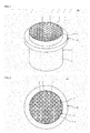
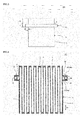
- the dust collecting honeycomb filter 100 of the present embodiment includes the flange section 23 disposed on the outer periphery 4 of the honeycomb base material 3 and having the porous flange partition walls 21 to define and form the plurality of flange cells 22. Moreover, the flange section 23 has a shape projecting outwardly from the outer periphery 4 of the honeycomb base material 3. Moreover, in the dust collecting honeycomb filter 100 of the present embodiment, it can be considered that an outer shape of the flange section 23 is such a shape that a central portion of a disc (a column) is hollowed out. As shown in Figs.
- the flange section 23 is preferably formed in a ring shape extending in a peripheral direction of the outer periphery 4 of the honeycomb base material 3 (a continuous ring shape), but it is also a preferable configuration that the flange section is formed in "an intermittent ring shape" in which a part of the ring shape is missing.
- the flange section 23 has the flange plugging portions 24 disposed in "the open frontal areas of the flange cells 22" in both end surfaces in the extending direction D2 of the flange cells 22 (one "end surface 25 of the flange section” and the other "end surface 25 of the flange section”). Moreover, the length, in the extending direction D2 of the flange cells 22, of the flange plugging portion 24a positioned on the innermost side in the flange section 23 is from 1.0 to 2.5 mm. When the length of the flange plugging portion 24a in the extending direction D2 of the flange cells 22 is smaller than 1.0 mm, the flange plugging portion 24a unfavorably easily drops due to vibration or the like during use. When the length is in excess of 2.5 mm and the dust collecting honeycomb filter 100 is used as the DPF, cracks are unfavorably generated in a root portion of the flange section 23 of the dust collecting honeycomb filter 100 due to the heat shock during the recovery.
- the length, in the extending direction D2 of the flange cells 22, of the flange plugging portion 24b positioned on the outermost side in the flange section 23 is 3.0 mm or more.
- the length of the flange plugging portion 24b in the extending direction D2 of the flange cells 22 is preferably from 3.0 to 7.0 mm.
- chips or cracks are unfavorably generated due to the mutual collision or the contact of the flange sections 23, the collision or the contact of the flange section 23 with the other object, or the like.
- the length of the flange plugging portion 24b in the extending direction D2 of the flange cells 22 is in excess of 7.0 mm, a long time is required for formation of the flange plugging portions sometimes.
- the flange plugging portion 24 positioned on an inner side in the flange section 23 is preferably shorter. That is, the flange plugging portion length preferably successively decreases stepwise from the flange plugging portion 24b positioned on the outermost side toward the flange plugging portion 24a positioned on the innermost side in the flange section 23. In consequence, impact force or heat stress can be scattered, and shock resistance and heat resistance can be enhanced.
- the length in "the direction D2" of the flange plugging portion 24b positioned on the outermost side in the flange section 23 is preferably 1 mm or more larger than the length in "the direction D2" of the flange plugging portion 24a positioned on the innermost side in the flange section 23.
- a length in "the direction D1" of the plugging portion of the honeycomb base material 3 is preferably 1.5 mm or more larger than the largest value of the length in "the direction D2" of the flange plugging portion of the flange section.
- respective cell structures of the flange section 23 and the honeycomb base material 3 are preferably the same.
- the cell structure means the cell density (cells/cm 2 ), the partition wall thickness ( ⁇ m), and the cell shape (a cross sectional shape perpendicular to the cell extending direction).
- the formed honeycomb body including the portions corresponding to the flange section 23 and the honeycomb base material 3 is formed by the extrusion forming, and predetermined portions are ground and removed, whereby the dust collecting honeycomb filter can be prepared. Therefore, the dust collecting honeycomb filter can easily be manufactured.
- the thickness H of the flange section 23 in the cross section perpendicular to the extending direction of the cells 2 is smaller than 1 mm, the flange section is thin, and hence strength lowers sometimes.
- the thickness is in excess of 30 mm, the flange section is not easily assembled to a piping line, or is not easily handled sometimes.
- the thickness H of the flange section 23 in the cross section perpendicular to the extending direction of the cells 2 is a thickness on the basis of a position of the surface of the outer periphery coating wall.
- a width L of the flange section 23 is preferably from 1 to 90%, further preferably from 3 to 50%, and especially preferably from 5 to 30% of the length of the dust collecting honeycomb filter 100 in the cell extending direction.
- the width L of the flange section is the length of the flange section in the cell extending direction of the dust collecting honeycomb filter 100.
- the dust collecting honeycomb filter 100 When the percentage is in excess of 90%, the dust collecting honeycomb filter 100 enlarges, and there is the fear that the dust collecting honeycomb filter 100 cannot suitably be fixed to the limited space in the dust collector.
- the width L of the flange section is a distance between both tips of both tapered ends as shown in Fig. 9 .
- the width L of the flange section 23 is the thickness on the basis of the position of the surface of the outer periphery coating wall.
- the flange section 23 may be disposed at any position of the honeycomb base material 3 in the extending direction of the cells 2.
- the flange section may be disposed in the central portion of the honeycomb base material 3, may be disposed at the end thereof, or may be interposed between the central portion of the honeycomb base material 3 and the end thereof as shown in Fig. 1 .
- the central portion of the honeycomb base material is the central portion of the honeycomb base material in the cell extending direction.
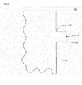
- a portion connected to a honeycomb base material on an inner side preferably has a curvedly extended shape in the cross section including the central axis.
- This portion of the flange section 23 will be referred to as a curved skirt portion 27.
- the curved skirt portion 27 is preferably circular.
- a radius of the circle of the curved skirt portion 27 is preferably from 0.2 to 10 mm.
- the flange section has the curved skirt portion 27, whereby the stress concentration can be suppressed, and the damage of the dust collecting honeycomb filter can be suppressed.
- the dust collecting honeycomb filter 200 of the present embodiment preferably has the same constitution as the above-mentioned one embodiment of the dust collecting honeycomb filter of the present invention, except the above shape of the flange section 23.
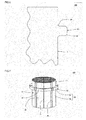
- a portion connected to a honeycomb base material on an inner side preferably has a linearly extended shape in the cross section including the central axis.
- This portion of the flange section 23 will be referred to as a linear skirt portion 29.
- the flange section has the linear skirt portion 29, whereby the stress concentration can be suppressed, and the damage of the dust collecting honeycomb filter can be suppressed.
- the outer periphery of the honeycomb base material 3 and the surface of the flange section 23 preferably include an outer periphery coating wall 6.
- a thickness of the outer periphery coating wall 6 is preferably from 0.05 to 3.0 mm, further preferably from 0.1 to 2.5 mm, and especially preferably from 0.2 to 2.0 mm.
- the outer periphery coating wall is excessively thin, and a mechanical strength of an outer periphery coating honeycomb structure lowers sometimes.
- the thickness is larger than 3.0 mm, the outer periphery coating wall is excessively thick.
- the outer periphery coating honeycomb structure is excessively large sometimes.
- a material of the outer periphery coating wall 6 is preferably a material obtained by adding additives such as an organic binder, resin balloons and a dispersant to "an inorganic raw material such as inorganic fiber, colloidal silica, clay or SiC particles" or "the same material as a plugging material described later" and further adding water, followed by kneading, or the like.
- the material of the outer periphery coating wall 6 and a material of flange plugging portions 24 are more preferably the same material. Furthermore, it is also a preferable configuration that a part of the outer periphery coating wall 6 is projected (inserted) into flange cells and that portions inserted into the flange cells are the flange plugging portions 24.
- a further embodiment of the dust collecting honeycomb filter of the present invention is such a segment type dust collecting honeycomb filter 400 as shown in Fig. 7 .
- the dust collecting honeycomb filter 400 of the present embodiment is the dust collecting honeycomb filter 400 including a plurality of honeycomb segments 35 each having a honeycomb segment base material 32 and a flange segment 42 disposed on the side surface of the honeycomb segment base material 32.
- a portion obtained by joining the plurality of honeycomb segment base materials 32 is a honeycomb base material 33.
- a portion obtained by joining the plurality of flange segments 42 is a flange section 43.
- the segment type dust collecting honeycomb filter 400 shown in Fig. 7 does not include an outer periphery coating wall, but it is also a preferable configuration that the filter includes the outer periphery coating wall.
- the dust collecting honeycomb filter 400 of the present embodiment preferably has a constitution similar to one embodiment (the dust collecting honeycomb filter 100 ( Fig. 1 )) of the above-mentioned dust collecting honeycomb filter of the present invention, except a shape in which the plurality of honeycomb segments 35 are joined. Also in the dust collecting honeycomb filter 400 of the present embodiment, partition walls of the honeycomb segment base materials 32 and partition walls (flange partition walls) of the flange segments 42 are continuously connected without forming any boundaries therein. Therefore, in the connection between the honeycomb base material 33 and the flange section 43, the partition walls and the flange partition walls are continuously connected without forming any boundaries therein.
- the dust collecting honeycomb filter of the present invention can be manufactured by a method in the following. That is, the dust collecting honeycomb filter of the present invention can be manufactured by a method having a fired honeycomb body preparing step of preparing a fired honeycomb body, and a cutting step of cutting an outer peripheral portion of this fired honeycomb body to form the flange section. Furthermore, when the outer periphery coating wall is disposed, the method preferably has an outer periphery coating wall forming step, after cutting the outer peripheral portion of the fired honeycomb body.
- the fired honeycomb body is a fired honeycomb body including porous partition walls formed by firing a ceramic raw material, to define and form a plurality of cells that become through channels of a fluid.
- the fired honeycomb body preparing step is a step of preparing the fired honeycomb body including the porous partition walls formed by firing the ceramic raw material. There is not any special restriction on a method of preparing the fired honeycomb body. Hereinafter, the fired honeycomb body preparing step will be described stepwise in divided steps.
- a ceramic forming raw material containing the ceramic raw material is preferably formed to obtain the formed honeycomb body including partition walls (unfired) to define and form a plurality of cells that become through channels of a fluid.
- the formed honeycomb body is a formed body of a honeycomb structure.
- the ceramic raw material to be contained in the ceramic forming raw material is preferably at least one selected from the group consisting of a cordierite forming raw material, cordierite, silicon carbide, a silicon-silicon carbide composite material, mullite, aluminum titanate, zeolite, and vanadium.
- the cordierite forming raw material is the ceramic raw material blended so as to have a chemical composition in which silica falls in a range of 42 to 56 mass%, alumina falls in a range of 30 to 45 mass% and magnesia falls in a range of 12 to 16 mass%.
- the cordierite forming raw material is fired to become cordierite.
- the ceramic forming raw material is preferably prepared by mixing the above ceramic raw material with a dispersion medium, an organic binder, an inorganic binder, a pore former, a surfactant and the like.
- a dispersion medium an organic binder, an inorganic binder, a pore former, a surfactant and the like.
- a preferable example of the method is a method of extrusion-forming the material by use of "a die" from which the formed honeycomb body having a desirable cell shape, partition wall thickness or cell density is formed, to obtain the formed honeycomb body.
- a die As a material of the die, a cemented carbide which does not easily wear down is preferable.
- Examples of a shape of the formed honeycomb body include a columnar shape, an elliptic shape, and a tubular shape in which end surfaces have a polygonal shape such as "a square shape, a rectangular shape, a triangular shape, a pentangular shape, a hexagonal shape, or an octagonal shape".
- the obtained formed honeycomb body may be dried.
- a drying method include hot air drying, microwave drying, dielectric drying, reduced-pressure drying, vacuum drying, and freeze-drying. Above all, the dielectric drying, the microwave drying, the hot air drying or any combination of these methods is preferably performed.
- the formed honeycomb body is fired to prepare the fired honeycomb body.
- the formed honeycomb body Prior to the firing (final firing) of the formed honeycomb body, the formed honeycomb body is preferably calcinated.
- the calcinating is performed for degreasing.
- organic substances the organic binder, the surfactant, the pore former, etc.
- a burning temperature of the organic binder is from about 100 to 300°C
- a burning temperature of the pore former is from about 200 to 800°C. Therefore, as calcinating conditions, heating is preferably performed at about 200 to 1000°C in an oxidation atmosphere for about three to 100 hours.
- the cutting step is a step of cutting the outer peripheral portion of the fired honeycomb body to form the flange section.
- the outer periphery of the fired honeycomb body is cut, to create shapes of the honeycomb base material and the flange section. That is, "the formed honeycomb body formed in a state where the forming raw material is continuously connected" is prepared by the extrusion forming, and the fired honeycomb body obtained by firing the formed honeycomb body is cut and processed to form the honeycomb base material and the flange section. Therefore, the partition walls and the flange partition walls are continuously connected without forming any boundaries therein.
- a method of cutting the fired honeycomb body there is not any special restriction on a method of cutting the fired honeycomb body.
- a method of cutting the outer peripheral portion of the fired honeycomb body a heretofore known method can suitably be employed, but a technique of pressing a grindstone sprinkled with diamond while rotating the fired honeycomb body is preferable.
- a thickness of "the outer peripheral portion of the fired honeycomb body which is to be cut" in the cutting step is the same as a thickness of the flange section formed after the cutting.
- the cutting may be performed before or after the firing of the formed honeycomb body, but the cutting is preferably performed after the firing.
- the cutting is performed after the firing, whereby even when the fired honeycomb body is deformed by the firing, the shape of the fired honeycomb body can be arranged by the cutting.
- plugging step is preferably performed after the cutting step.
- plugging portions are disposed in open frontal areas of "predetermined cells” in one end surface and open frontal areas of "the remaining cells” in the other end surface of the fired honeycomb body. The step will specifically be described in the following.
- the plugging material is filled into the cell open frontal areas of the one end surface of the fired honeycomb body (the honeycomb base material).
- a method having a masking step and a press-in step is preferable.
- the masking step is a step of attaching a sheet to the one end surface of the fired honeycomb body, and making holes at positions of the sheet which overlap with "cells to be provided with the plugging portions”.
- the press-in step is a step of pressing "an end of the fired honeycomb body to which the sheet is attached" into a container which contains the plugging material, to press the plugging material into the cells of the fired honeycomb body.
- the plugging material filled into the fired honeycomb body is preferably dried.
- the dust collecting honeycomb filter of the present invention is the segment type dust collecting honeycomb filter 400 as shown in Fig. 7
- the dust collecting honeycomb filter is preferably prepared as follows. First, a plurality of fired honeycomb segment bodies are prepared, and as shown in Fig. 8 , a plurality of obtained fired honeycomb segment bodies 12 are preferably joined by a joining material 13, to obtain a joined honeycomb segment assembly 11. Then, an outer periphery of the joined honeycomb segment assembly 11 is preferably cut and processed to form the honeycomb base material and the flange section, and the plugging portions are preferably formed to prepare the dust collecting honeycomb filter.
- Fig. 8 is a perspective view schematically showing the joined honeycomb segment assembly prepared in a manufacturing process in the manufacturing method of the dust collecting honeycomb filter of the present invention.
- the fired honeycomb segment bodies can be prepared by the above-mentioned preparing method of "the fired honeycomb body". Moreover, there is not any special restriction on a material of the joining material 13, but a slurry or the like is preferable which is obtained by adding an organic binder, resin balloons, a dispersant and the like to inorganic fiber, colloidal silica, clay, or ceramic particles such as SiC particles or cordierite particles, and further adding water, followed by kneading. Examples
- the dried formed honeycomb body was fired on conditions of the highest temperature of 1420°C and 100 hours to obtain a fired honeycomb body.
- an outer peripheral portion of the obtained columnar fired honeycomb body was cut so that a honeycomb base material and a flange section were formed. In this way, the honeycomb base material and the flange section were formed.
- a method of cutting the outer peripheral portion of the fired honeycomb body was a method of pressing a grindstone sprinkled with diamond onto the outer peripheral portion of the fired honeycomb body while rotating the fired honeycomb body.
- the obtained honeycomb base material of the dust collecting honeycomb filter had a columnar shape in which a diameter of the honeycomb base material in a cross section perpendicular to a cell extending direction was 160 mm, and a length thereof in the cell extending direction was 210 mm. Moreover, a distance (a position where the flange section was formed on the basis of one end surface of the honeycomb base material) X between one end surface of the honeycomb base material and the end surface of the flange section which faced the same direction as the one end surface of the honeycomb base material was 65 mm. A length (a width of the flange section) L of the flange section in the extending direction of the flange cells was 20 mm.
- a thickness (a thickness of the flange section; a length in a diametric direction) H (see Fig. 3 ) of a flange section 23 in the cross section perpendicular to the cell extending direction was 10 mm.
- both a partition wall thickness and a flange partition wall thickness were 180 ⁇ m.
- both a cell density and a flange cell density were 62 cells/cm 2 .
- a length of each plugging portion formed in the honeycomb base material in the cell extending direction was 2.5 mm.
- a shape of the cross section of each cell of the honeycomb base material which was perpendicular to the cell extending direction was a square shape.
- the distance X is a distance between one end surface of the honeycomb base material and an intersection of "the end surface of the flange section" on the side of "the one end surface of the honeycomb base material” and the outer periphery of the honeycomb base material, as shown in Fig. 9 .
- a column of "H” indicates a thickness (mm) of the flange section 23 in the cross section perpendicular to the cell extending direction.
- a column of "L” indicates a length (mm) of the flange section in the extending direction of the flange cells.
- a column of " ⁇ ” indicates a tilt angle (°) of the end surface of the flange section. ⁇ was the same angle on both one end surface side and the other end surface side of the honeycomb base material, but may be a different angle.
- each of thicknesses of the plugging portions formed at both ends of each flange cell of "the flange outer peripheral portion” is a thickness of 0.5 time as much as a length of "the flange outer peripheral portion”.
- the plugging portions at both the ends of each flange cell of "the flange outer peripheral portion” are connected in the flange cell.
- a burning gas including soot generated by burning a diesel fuel (light oil) was allowed to flow into the dust collecting honeycomb filter from one end surface and flow out from the other end surface, whereby the soot was deposited on the dust collecting honeycomb filter. Then, cooling was once performed down to room temperature (25°C). Afterward, from the above one end surface of the dust collecting honeycomb filter, the burning gas of 680°C was allowed to flow into the filter to burn the soot. Then, when the soot was burned to lower a pressure loss of the dust collecting honeycomb filter, a flow rate of the burning gas was decreased, to rapidly burn the soot. Afterward, the presence/absence of the generation of the cracks in the dust collecting honeycomb filter was confirmed.
- the other dust collecting honeycomb filter is disposed at a position which is 150 cm apart from the above "one end” of “the roller conveyor for transfer” (the end on the side of “the still standing roller conveyor”).
- “the roller conveyor for transfer” is tilted, to move the dust collecting honeycomb filter disposed on “the roller conveyor for transfer”, so that the filter collides with the dust collecting honeycomb filter allowed to stand still on “the still standing roller conveyor”.
- the tilt of "the roller conveyor for transfer” is regulated so that the dust collecting honeycomb filters collide with each other at 1.5 m/second.
- the two dust collecting honeycomb filters collide on "the still standing roller conveyor" in a state where a central axis is parallel (a state where the end surfaces are parallel to each other). Collision portions of the two dust collecting honeycomb filters are flange sections.
- A means that there is not any damage on the dust collecting honeycomb filter. It is to be noted that a case where a hit trace can visually be recognized but any chips or cracks are not generated corresponds to "A”.
- “B” means that the chips and/or the cracks are generated in the flange section.
- the chips mean that broken pieces are detached due to damage (or a state where the pieces can be detached).
- Dust collecting honeycomb filters were obtained in the same manner as in Example 1 except that conditions were changed as shown in Table 1.
- a tilt angle ⁇ of a flange section of each dust collecting honeycomb filter other than "Example 2 and Comparative Example 1" was a value in excess of 0°.
- the tilt angle ⁇ is an angle obtained by subtracting 90° from "the angle ⁇ between the end surface of the flange section 23 and the side surface of the honeycomb base material 3" as shown in Fig. 9.
- Fig. 9 showing a dust collecting honeycomb filter 500 is a front view schematically showing the dust collecting honeycomb filter of Example 3.
- the soot mass limit test and "the collision test” were carried out by the above methods. The results are shown in Table 1.
- a ceramic raw material 80 parts by mass of SiC powder and 20 parts by mass of metal Si powder were mixed.
- a pore former As the pore former, starch was used.
- a binder methylcellulose and hydroxypropoxyl methylcellulose were used.
- the surfactant sodium laurate was used. Amounts of the respective raw materials to be added were 5 parts by mass of the pore former, 3 parts by mass of methylcellulose, 3 parts by mass of hydroxypropoxyl methylcellulose, 1 part by mass of the surfactant, and 32 parts by mass of water, to 100 parts by mass of the ceramic raw material.
- An obtained kneaded material was extrusion-formed by using a die for forming a formed honeycomb body, and dried by microwaves and hot air, to obtain a dried honeycomb body.
- the obtained dried honeycomb body was degreased at about 400°C in the air atmosphere.
- the degreased dried honeycomb body was fired at about 1450°C in an argon inert atmosphere, to bind SiC crystal particles by Si, thereby obtaining a fired honeycomb segment body.
- a cross section perpendicular to a cell extending direction was a square with one side of 50 mm, and a length in the cell extending direction was 210 mm.
- a cell density was 62 cells/cm 2
- a partition wall thickness was 180 ⁇ m.
- each of two of the fired honeycomb segment bodies was divided into two equal portions so that it was possible to obtain two fired honeycomb segment bodies in which each cross section perpendicular to the cell extending direction had an isosceles triangular shape.
- Respective side surfaces of the obtained 16 fired honeycomb segment bodies were joined to each other by a joining material, and dried, to obtain the joined honeycomb segment assembly 11 in which a shape of a cross section perpendicular to a central axis was an octagonal shape as shown in Fig. 8 .
- a joining material a material obtained by adding silica fiber, an organic binder and water to alumina powder was used. Additionally, a thickness of the joining material between the segments was about 1 mm.
- each obtained columnar fired honeycomb segment body was cut so that a honeycomb base material and a flange section were formed.
- the honeycomb base material and the flange section were formed.
- a method of cutting the outer peripheral portion of the fired honeycomb segment body was a method of pressing a grindstone sprinkled with diamond onto the outer peripheral portion of the fired honeycomb segment body while rotating the fired honeycomb segment body.
- Each end surface of the flange section was not provided with a tilt angle.
- an outer periphery coating material was applied to the outer periphery of the cut fired honeycomb segment body (the side surface of the honeycomb base material and the surface of the flange section) to form an outer periphery coating wall, thereby obtaining a dust collecting honeycomb filter.
- the end surface of the flange section was pressed with a spatula, to push the outer periphery coating material into flange cells, thereby forming flange plugging portions.
- the honeycomb base material of the obtained dust collecting honeycomb filter had a columnar shape in which a diameter of the honeycomb base material in a cross section perpendicular to a cell extending direction was 160 mm, and a length thereof in the cell extending direction was 210 mm. Moreover, a distance (a position where the flange section was formed on the basis of one end surface of the honeycomb base material) X between one end surface of the honeycomb base material and the end surface of the flange section which faced the same direction as the one end surface of the honeycomb base material was 65 mm. A length (a width of the flange section) L (see Fig. 3 ) of a flange section 23 in the extending direction of the flange cells was 20 mm.
- a thickness (a thickness of the flange section; a length in a diametric direction) H (see Fig. 3 ) of the flange section 23 in the cross section perpendicular to the cell extending direction was 10 mm.
- both a partition wall thickness and a flange partition wall thickness were 180 ⁇ m.
- both a cell density and a flange cell density were 62 cells/cm 2 .
- a length of each plugging portion formed in the honeycomb base material in the cell extending direction was 2.5 mm.
- a shape of the cross section of each cell of the honeycomb base material which was perpendicular to the cell extending direction was a square shape.
- a length ("a plugging portion thickness” of "a flange outer peripheral portion”), in the extending direction of the flange cells, of the flange plugging portion positioned on the outermost side in the flange section was 3.0 mm.
- a length ("a plugging portion thickness” of "a flange inner peripheral portion"), in the extending direction of the flange cells, of the flange plugging portion positioned on the innermost side in the flange section was 1.0 mm.
- the length of the flange plugging portion in the flange section "in the extending direction of the flange cells” was larger close to the flange outer peripheral portion.
- the partition walls and flange partition walls were continuously connected without forming any boundaries therein.
- Dust collecting honeycomb filters were obtained in the same manner as in Example 24 except that conditions were changed as shown in Table 2.
- planar flat surface portions 51 parallel to a cell extending direction were formed in a flange section 23.
- the four flat surface portions 51 were formed, and two pairs of flat surface portions 51 parallel to each other in one pair (two) were formed.
- An angle formed by one "pair of flat surface portions 51" and the other "pair of flat surface portions 51" was 90°. That is, in a cross section perpendicular to the cell extending direction, the flat surface portion 51 was formed every 90° in an outer peripheral direction (a rotating direction around a central axis).
- a distance between the flat surface portion 51 and a honeycomb base material 3 was 10 mm. It can be considered that "the distance between the flat surface portion 51 and the honeycomb base material 3" is "a thickness of the flange section 23 in the flat surface portion 51".
- a dust collecting honeycomb filter 600 shown in Fig. 10 partition walls and cells of the honeycomb base material 3 are omitted.
- Fig. 10 is a plan view schematically showing the dust collecting honeycomb filter 600 of Example 45.
- each of the dust collecting honeycomb filters of Example 46 and Comparative Examples 13 and 20 there were formed four flat surface portions similar to those of the dust collecting honeycomb filter 600 of Example 45.
- each flange section is not easily damaged during collision, as compared with the dust collecting honeycomb filters of Comparative Examples 1, 2 and 6 to 8. Moreover, it is seen that in the dust collecting honeycomb filters of Examples 1 to 23, generation of cracks of a root portion of each flange section due to "heat shock during recovery” is suppressed during use as a DPF, as compared with the dust collecting honeycomb filters of Comparative Examples 1 to 5 and 8 to 11.
Landscapes
- Chemical & Material Sciences (AREA)
- Engineering & Computer Science (AREA)
- Chemical Kinetics & Catalysis (AREA)
- Physics & Mathematics (AREA)
- Geometry (AREA)
- Mechanical Engineering (AREA)
- Combustion & Propulsion (AREA)
- General Engineering & Computer Science (AREA)
- Ceramic Engineering (AREA)
- Health & Medical Sciences (AREA)
- Toxicology (AREA)
- Filtering Materials (AREA)
- Filtering Of Dispersed Particles In Gases (AREA)
Applications Claiming Priority (2)
| Application Number | Priority Date | Filing Date | Title |
|---|---|---|---|
| JP2012231511 | 2012-10-19 | ||
| PCT/JP2013/068817 WO2014061320A1 (fr) | 2012-10-19 | 2013-07-10 | Filtre en nid d'abeilles de collecte de poussières |
Publications (3)
| Publication Number | Publication Date |
|---|---|
| EP2745910A1 true EP2745910A1 (fr) | 2014-06-25 |
| EP2745910A4 EP2745910A4 (fr) | 2015-06-03 |
| EP2745910B1 EP2745910B1 (fr) | 2019-03-27 |
Family
ID=50487898
Family Applications (1)
| Application Number | Title | Priority Date | Filing Date |
|---|---|---|---|
| EP13814815.0A Active EP2745910B1 (fr) | 2012-10-19 | 2013-07-10 | Filtre en nid d'abeilles de collecte de poussières |
Country Status (5)
| Country | Link |
|---|---|
| US (1) | US9205363B2 (fr) |
| EP (1) | EP2745910B1 (fr) |
| JP (1) | JP6092841B2 (fr) |
| CN (1) | CN203710819U (fr) |
| WO (1) | WO2014061320A1 (fr) |
Families Citing this family (17)
| Publication number | Priority date | Publication date | Assignee | Title |
|---|---|---|---|---|
| US10603633B2 (en) | 2012-02-24 | 2020-03-31 | Corning Incorporated | Honeycomb structure comprising a cement skin composition with crystalline inorganic fibrous material |
| JP5684208B2 (ja) * | 2012-09-25 | 2015-03-11 | 日本碍子株式会社 | ハニカム構造体の研削方法 |
| JP5805039B2 (ja) * | 2012-09-25 | 2015-11-04 | 日本碍子株式会社 | ハニカム構造体 |
| JP6068274B2 (ja) * | 2013-06-11 | 2017-01-25 | 日本碍子株式会社 | ハニカム構造体 |
| PL3137432T3 (pl) * | 2014-05-01 | 2018-11-30 | Corning Incorporated | Struktura plastra miodu zawierająca kompozycję mleczka cementowego z krystalicznym nieorganicznym materiałem włóknistym oraz sposób jej wytwarzania |
| JP6382613B2 (ja) * | 2014-07-18 | 2018-08-29 | 日本特殊陶業株式会社 | 流体分離装置 |
| USD785678S1 (en) * | 2014-12-24 | 2017-05-02 | Ngk Insulators, Ltd. | Catalyst carrier for exhaust gas purification |
| USD780808S1 (en) | 2014-12-24 | 2017-03-07 | Ngk Insulators, Ltd. | Catalyst carrier for exhaust gas purification |
| JP6534822B2 (ja) * | 2015-01-29 | 2019-06-26 | イビデン株式会社 | ハニカム構造体及びその製造方法 |
| JP6396816B2 (ja) * | 2015-01-29 | 2018-09-26 | イビデン株式会社 | ハニカム構造体の製造方法 |
| CN107207370A (zh) * | 2015-02-05 | 2017-09-26 | 日本碍子株式会社 | 蜂窝结构体 |
| JP6667342B2 (ja) * | 2016-03-30 | 2020-03-18 | 日本碍子株式会社 | ハニカム構造体 |
| JP6669592B2 (ja) * | 2016-06-01 | 2020-03-18 | イビデン株式会社 | ハニカム構造体 |
| JP6697364B2 (ja) * | 2016-09-30 | 2020-05-20 | 日本碍子株式会社 | ハニカム構造体 |
| JP6615802B2 (ja) | 2017-02-06 | 2019-12-04 | 日本碍子株式会社 | 目封止ハニカム構造体の製造方法 |
| KR20190029477A (ko) | 2017-09-11 | 2019-03-20 | 엘지전자 주식회사 | 휴대용 공기정화기 |
| USD928912S1 (en) * | 2020-02-12 | 2021-08-24 | Unicat Catalyst Technologies, Inc. | Filter |
Family Cites Families (20)
| Publication number | Priority date | Publication date | Assignee | Title |
|---|---|---|---|---|
| CH562396A5 (fr) * | 1972-09-04 | 1975-05-30 | Eberspaecher J Fa | |
| US5149475A (en) * | 1988-07-28 | 1992-09-22 | Ngk Insulators, Ltd. | Method of producing a honeycomb structure |
| JPH074534B2 (ja) * | 1988-09-22 | 1995-01-25 | 日本碍子株式会社 | ハニカム構造体およびその製造法 |
| JP2705731B2 (ja) * | 1989-11-28 | 1998-01-28 | 日本碍子株式会社 | ハニカム構造体 |
| JP3110247B2 (ja) * | 1993-06-28 | 2000-11-20 | 日本碍子株式会社 | 除塵装置 |
| JP3012167B2 (ja) * | 1995-04-12 | 2000-02-21 | 日本碍子株式会社 | 排ガス浄化フィルタおよびそれを用いた排ガス浄化装置 |
| US5656245A (en) * | 1995-11-14 | 1997-08-12 | Nippon Reinz Co., Ltd. | Catalytic converter for cleaning exhaust gas |
| JP3432061B2 (ja) | 1995-11-29 | 2003-07-28 | 日本碍子株式会社 | 集塵装置におけるフィルタエレメントの支持構造 |
| JP3971066B2 (ja) | 1999-09-13 | 2007-09-05 | 日本碍子株式会社 | フランジ付きフィルタの製造方法 |
| JP3471712B2 (ja) * | 2000-05-09 | 2003-12-02 | 日本碍子株式会社 | セラミックハニカムフィルタ及びその製造方法 |
| JP4259787B2 (ja) * | 2000-10-26 | 2009-04-30 | イビデン株式会社 | ハニカムフィルタ及び排気ガス浄化装置 |
| US6919052B2 (en) * | 2000-12-04 | 2005-07-19 | Delphi Technologies, Inc. | Catalytic converter |
| JP4511070B2 (ja) * | 2001-03-29 | 2010-07-28 | 日本碍子株式会社 | ハニカム構造体及びそのアッセンブリ |
| JP4735917B2 (ja) * | 2001-05-15 | 2011-07-27 | 日立金属株式会社 | セラミックハニカムフィルタ |
| JP3971215B2 (ja) * | 2002-03-13 | 2007-09-05 | 日本碍子株式会社 | 排ガス浄化用フィルター |
| US7090714B2 (en) * | 2002-06-17 | 2006-08-15 | Hitachi Metals, Ltd. | Ceramic honeycomb filter |
| JP2005270755A (ja) * | 2004-03-24 | 2005-10-06 | Ngk Insulators Ltd | ハニカム構造体及びその製造方法 |
| KR20090125033A (ko) * | 2007-03-27 | 2009-12-03 | 니뽄 가이시 가부시키가이샤 | 밀봉 허니컴 구조체 |
| WO2009118816A1 (fr) * | 2008-03-24 | 2009-10-01 | イビデン株式会社 | Structure en nid d'abeille |
| JP5877622B2 (ja) | 2009-02-13 | 2016-03-08 | 日本碍子株式会社 | ハニカム構造体 |
-
2013
- 2013-07-10 JP JP2014501338A patent/JP6092841B2/ja active Active
- 2013-07-10 EP EP13814815.0A patent/EP2745910B1/fr active Active
- 2013-07-10 CN CN201390000092.2U patent/CN203710819U/zh not_active Expired - Lifetime
- 2013-07-10 WO PCT/JP2013/068817 patent/WO2014061320A1/fr not_active Ceased
-
2014
- 2014-01-10 US US14/152,292 patent/US9205363B2/en active Active
Also Published As
| Publication number | Publication date |
|---|---|
| EP2745910B1 (fr) | 2019-03-27 |
| JPWO2014061320A1 (ja) | 2016-09-05 |
| EP2745910A4 (fr) | 2015-06-03 |
| CN203710819U (zh) | 2014-07-16 |
| JP6092841B2 (ja) | 2017-03-08 |
| WO2014061320A1 (fr) | 2014-04-24 |
| US20140123612A1 (en) | 2014-05-08 |
| US9205363B2 (en) | 2015-12-08 |
Similar Documents
| Publication | Publication Date | Title |
|---|---|---|
| EP2745910B1 (fr) | Filtre en nid d'abeilles de collecte de poussières | |
| EP1473445B1 (fr) | Structure filtrante en nid d'abeilles | |
| EP2368619B1 (fr) | Structures de céramique en nid d'abeille | |
| US9416057B2 (en) | Honeycomb structure | |
| JP5231305B2 (ja) | ハニカム構造体及び接合型ハニカム構造体 | |
| EP2484504B1 (fr) | Méthode d'une fabrication d'une structure en nid d'abeilles | |
| EP2746241B1 (fr) | Filtre de collecte de particules fines | |
| EP2127719B1 (fr) | Structure en nid d'abeille | |
| EP2712668A1 (fr) | Filtre en nids d'abeilles | |
| JP5378994B2 (ja) | ハニカムセグメント成形用口金、及びハニカム構造体の製造方法 | |
| EP2366677A1 (fr) | Corps structuré en nid d'abeille | |
| EP2698190A1 (fr) | Structure en nid d'abeille raccordée | |
| EP2727895A1 (fr) | Filtre en SiC en nids d'abeilles avec liant contenant cordierite | |
| EP2374775B1 (fr) | Procede de fabrication de structures en nid d'abeilles | |
| EP2481542A1 (fr) | Structure de nid d'abeilles et son procédé de fabrication | |
| US20140363616A1 (en) | Honeycomb structure | |
| US20140287190A1 (en) | Honeycomb structure | |
| JP5351678B2 (ja) | ハニカム構造体 | |
| JP6521683B2 (ja) | ハニカム構造体 | |
| EP2380648A1 (fr) | Corps structuré en nid d'abeille | |
| EP2221099B1 (fr) | Structure en nid d'abeille | |
| US9470131B2 (en) | Honeycomb structure | |
| JP2011190740A (ja) | ハニカム構造体 | |
| US11426688B2 (en) | Honeycomb structure and method for producing honeycomb structure | |
| JP6595194B2 (ja) | ハニカム構造体 |
Legal Events
| Date | Code | Title | Description |
|---|---|---|---|
| PUAI | Public reference made under article 153(3) epc to a published international application that has entered the european phase |
Free format text: ORIGINAL CODE: 0009012 |
|
| 17P | Request for examination filed |
Effective date: 20140128 |
|
| AK | Designated contracting states |
Kind code of ref document: A1 Designated state(s): AL AT BE BG CH CY CZ DE DK EE ES FI FR GB GR HR HU IE IS IT LI LT LU LV MC MK MT NL NO PL PT RO RS SE SI SK SM TR |
|
| RA4 | Supplementary search report drawn up and despatched (corrected) |
Effective date: 20150508 |
|
| RIC1 | Information provided on ipc code assigned before grant |
Ipc: F01N 3/022 20060101ALI20150430BHEP Ipc: B01D 39/20 20060101ALI20150430BHEP Ipc: F01N 3/28 20060101ALI20150430BHEP Ipc: B01D 46/24 20060101ALI20150430BHEP Ipc: B01D 46/00 20060101AFI20150430BHEP Ipc: C04B 41/85 20060101ALI20150430BHEP |
|
| DAX | Request for extension of the european patent (deleted) | ||
| REG | Reference to a national code |
Ref country code: DE Ref legal event code: R079 Ref document number: 602013053043 Country of ref document: DE Free format text: PREVIOUS MAIN CLASS: B01D0046000000 Ipc: B01D0046240000 |
|
| GRAP | Despatch of communication of intention to grant a patent |
Free format text: ORIGINAL CODE: EPIDOSNIGR1 |
|
| STAA | Information on the status of an ep patent application or granted ep patent |
Free format text: STATUS: GRANT OF PATENT IS INTENDED |
|
| RIC1 | Information provided on ipc code assigned before grant |
Ipc: B01D 46/24 20060101AFI20180926BHEP Ipc: F01N 3/28 20060101ALI20180926BHEP Ipc: B01D 39/20 20060101ALI20180926BHEP Ipc: C04B 41/85 20060101ALI20180926BHEP Ipc: F01N 3/022 20060101ALI20180926BHEP |
|
| INTG | Intention to grant announced |
Effective date: 20181011 |
|
| GRAS | Grant fee paid |
Free format text: ORIGINAL CODE: EPIDOSNIGR3 |
|
| GRAA | (expected) grant |
Free format text: ORIGINAL CODE: 0009210 |
|
| STAA | Information on the status of an ep patent application or granted ep patent |
Free format text: STATUS: THE PATENT HAS BEEN GRANTED |
|
| AK | Designated contracting states |
Kind code of ref document: B1 Designated state(s): AL AT BE BG CH CY CZ DE DK EE ES FI FR GB GR HR HU IE IS IT LI LT LU LV MC MK MT NL NO PL PT RO RS SE SI SK SM TR |
|
| REG | Reference to a national code |
Ref country code: GB Ref legal event code: FG4D |
|
| REG | Reference to a national code |
Ref country code: CH Ref legal event code: EP |
|
| REG | Reference to a national code |
Ref country code: AT Ref legal event code: REF Ref document number: 1112361 Country of ref document: AT Kind code of ref document: T Effective date: 20190415 |
|
| REG | Reference to a national code |
Ref country code: IE Ref legal event code: FG4D |
|
| REG | Reference to a national code |
Ref country code: DE Ref legal event code: R096 Ref document number: 602013053043 Country of ref document: DE |
|
| PG25 | Lapsed in a contracting state [announced via postgrant information from national office to epo] |
Ref country code: FI Free format text: LAPSE BECAUSE OF FAILURE TO SUBMIT A TRANSLATION OF THE DESCRIPTION OR TO PAY THE FEE WITHIN THE PRESCRIBED TIME-LIMIT Effective date: 20190327 Ref country code: NO Free format text: LAPSE BECAUSE OF FAILURE TO SUBMIT A TRANSLATION OF THE DESCRIPTION OR TO PAY THE FEE WITHIN THE PRESCRIBED TIME-LIMIT Effective date: 20190627 Ref country code: SE Free format text: LAPSE BECAUSE OF FAILURE TO SUBMIT A TRANSLATION OF THE DESCRIPTION OR TO PAY THE FEE WITHIN THE PRESCRIBED TIME-LIMIT Effective date: 20190327 Ref country code: LT Free format text: LAPSE BECAUSE OF FAILURE TO SUBMIT A TRANSLATION OF THE DESCRIPTION OR TO PAY THE FEE WITHIN THE PRESCRIBED TIME-LIMIT Effective date: 20190327 |
|
| REG | Reference to a national code |
Ref country code: NL Ref legal event code: MP Effective date: 20190327 |
|
| PG25 | Lapsed in a contracting state [announced via postgrant information from national office to epo] |
Ref country code: HR Free format text: LAPSE BECAUSE OF FAILURE TO SUBMIT A TRANSLATION OF THE DESCRIPTION OR TO PAY THE FEE WITHIN THE PRESCRIBED TIME-LIMIT Effective date: 20190327 Ref country code: NL Free format text: LAPSE BECAUSE OF FAILURE TO SUBMIT A TRANSLATION OF THE DESCRIPTION OR TO PAY THE FEE WITHIN THE PRESCRIBED TIME-LIMIT Effective date: 20190327 Ref country code: RS Free format text: LAPSE BECAUSE OF FAILURE TO SUBMIT A TRANSLATION OF THE DESCRIPTION OR TO PAY THE FEE WITHIN THE PRESCRIBED TIME-LIMIT Effective date: 20190327 Ref country code: BG Free format text: LAPSE BECAUSE OF FAILURE TO SUBMIT A TRANSLATION OF THE DESCRIPTION OR TO PAY THE FEE WITHIN THE PRESCRIBED TIME-LIMIT Effective date: 20190627 Ref country code: GR Free format text: LAPSE BECAUSE OF FAILURE TO SUBMIT A TRANSLATION OF THE DESCRIPTION OR TO PAY THE FEE WITHIN THE PRESCRIBED TIME-LIMIT Effective date: 20190628 Ref country code: LV Free format text: LAPSE BECAUSE OF FAILURE TO SUBMIT A TRANSLATION OF THE DESCRIPTION OR TO PAY THE FEE WITHIN THE PRESCRIBED TIME-LIMIT Effective date: 20190327 |
|
| REG | Reference to a national code |
Ref country code: AT Ref legal event code: MK05 Ref document number: 1112361 Country of ref document: AT Kind code of ref document: T Effective date: 20190327 |
|
| PG25 | Lapsed in a contracting state [announced via postgrant information from national office to epo] |
Ref country code: EE Free format text: LAPSE BECAUSE OF FAILURE TO SUBMIT A TRANSLATION OF THE DESCRIPTION OR TO PAY THE FEE WITHIN THE PRESCRIBED TIME-LIMIT Effective date: 20190327 Ref country code: SK Free format text: LAPSE BECAUSE OF FAILURE TO SUBMIT A TRANSLATION OF THE DESCRIPTION OR TO PAY THE FEE WITHIN THE PRESCRIBED TIME-LIMIT Effective date: 20190327 Ref country code: IT Free format text: LAPSE BECAUSE OF FAILURE TO SUBMIT A TRANSLATION OF THE DESCRIPTION OR TO PAY THE FEE WITHIN THE PRESCRIBED TIME-LIMIT Effective date: 20190327 Ref country code: PT Free format text: LAPSE BECAUSE OF FAILURE TO SUBMIT A TRANSLATION OF THE DESCRIPTION OR TO PAY THE FEE WITHIN THE PRESCRIBED TIME-LIMIT Effective date: 20190727 Ref country code: AL Free format text: LAPSE BECAUSE OF FAILURE TO SUBMIT A TRANSLATION OF THE DESCRIPTION OR TO PAY THE FEE WITHIN THE PRESCRIBED TIME-LIMIT Effective date: 20190327 Ref country code: RO Free format text: LAPSE BECAUSE OF FAILURE TO SUBMIT A TRANSLATION OF THE DESCRIPTION OR TO PAY THE FEE WITHIN THE PRESCRIBED TIME-LIMIT Effective date: 20190327 Ref country code: CZ Free format text: LAPSE BECAUSE OF FAILURE TO SUBMIT A TRANSLATION OF THE DESCRIPTION OR TO PAY THE FEE WITHIN THE PRESCRIBED TIME-LIMIT Effective date: 20190327 Ref country code: ES Free format text: LAPSE BECAUSE OF FAILURE TO SUBMIT A TRANSLATION OF THE DESCRIPTION OR TO PAY THE FEE WITHIN THE PRESCRIBED TIME-LIMIT Effective date: 20190327 |
|
| PG25 | Lapsed in a contracting state [announced via postgrant information from national office to epo] |
Ref country code: SM Free format text: LAPSE BECAUSE OF FAILURE TO SUBMIT A TRANSLATION OF THE DESCRIPTION OR TO PAY THE FEE WITHIN THE PRESCRIBED TIME-LIMIT Effective date: 20190327 Ref country code: PL Free format text: LAPSE BECAUSE OF FAILURE TO SUBMIT A TRANSLATION OF THE DESCRIPTION OR TO PAY THE FEE WITHIN THE PRESCRIBED TIME-LIMIT Effective date: 20190327 |
|
| PG25 | Lapsed in a contracting state [announced via postgrant information from national office to epo] |
Ref country code: AT Free format text: LAPSE BECAUSE OF FAILURE TO SUBMIT A TRANSLATION OF THE DESCRIPTION OR TO PAY THE FEE WITHIN THE PRESCRIBED TIME-LIMIT Effective date: 20190327 Ref country code: IS Free format text: LAPSE BECAUSE OF FAILURE TO SUBMIT A TRANSLATION OF THE DESCRIPTION OR TO PAY THE FEE WITHIN THE PRESCRIBED TIME-LIMIT Effective date: 20190727 |
|
| REG | Reference to a national code |
Ref country code: DE Ref legal event code: R097 Ref document number: 602013053043 Country of ref document: DE |
|
| PG25 | Lapsed in a contracting state [announced via postgrant information from national office to epo] |
Ref country code: DK Free format text: LAPSE BECAUSE OF FAILURE TO SUBMIT A TRANSLATION OF THE DESCRIPTION OR TO PAY THE FEE WITHIN THE PRESCRIBED TIME-LIMIT Effective date: 20190327 |
|
| PLBE | No opposition filed within time limit |
Free format text: ORIGINAL CODE: 0009261 |
|
| STAA | Information on the status of an ep patent application or granted ep patent |
Free format text: STATUS: NO OPPOSITION FILED WITHIN TIME LIMIT |
|
| PG25 | Lapsed in a contracting state [announced via postgrant information from national office to epo] |
Ref country code: MC Free format text: LAPSE BECAUSE OF FAILURE TO SUBMIT A TRANSLATION OF THE DESCRIPTION OR TO PAY THE FEE WITHIN THE PRESCRIBED TIME-LIMIT Effective date: 20190327 Ref country code: SI Free format text: LAPSE BECAUSE OF FAILURE TO SUBMIT A TRANSLATION OF THE DESCRIPTION OR TO PAY THE FEE WITHIN THE PRESCRIBED TIME-LIMIT Effective date: 20190327 |
|
| REG | Reference to a national code |
Ref country code: CH Ref legal event code: PL |
|
| 26N | No opposition filed |
Effective date: 20200103 |
|
| GBPC | Gb: european patent ceased through non-payment of renewal fee |
Effective date: 20190710 |
|
| PG25 | Lapsed in a contracting state [announced via postgrant information from national office to epo] |
Ref country code: TR Free format text: LAPSE BECAUSE OF FAILURE TO SUBMIT A TRANSLATION OF THE DESCRIPTION OR TO PAY THE FEE WITHIN THE PRESCRIBED TIME-LIMIT Effective date: 20190327 |
|
| REG | Reference to a national code |
Ref country code: BE Ref legal event code: MM Effective date: 20190731 |
|
| PG25 | Lapsed in a contracting state [announced via postgrant information from national office to epo] |
Ref country code: GB Free format text: LAPSE BECAUSE OF NON-PAYMENT OF DUE FEES Effective date: 20190710 |
|
| PG25 | Lapsed in a contracting state [announced via postgrant information from national office to epo] |
Ref country code: CH Free format text: LAPSE BECAUSE OF NON-PAYMENT OF DUE FEES Effective date: 20190731 Ref country code: BE Free format text: LAPSE BECAUSE OF NON-PAYMENT OF DUE FEES Effective date: 20190731 Ref country code: LI Free format text: LAPSE BECAUSE OF NON-PAYMENT OF DUE FEES Effective date: 20190731 Ref country code: LU Free format text: LAPSE BECAUSE OF NON-PAYMENT OF DUE FEES Effective date: 20190710 |
|
| PG25 | Lapsed in a contracting state [announced via postgrant information from national office to epo] |
Ref country code: FR Free format text: LAPSE BECAUSE OF NON-PAYMENT OF DUE FEES Effective date: 20190731 |
|
| PG25 | Lapsed in a contracting state [announced via postgrant information from national office to epo] |
Ref country code: IE Free format text: LAPSE BECAUSE OF NON-PAYMENT OF DUE FEES Effective date: 20190710 |
|
| PG25 | Lapsed in a contracting state [announced via postgrant information from national office to epo] |
Ref country code: CY Free format text: LAPSE BECAUSE OF FAILURE TO SUBMIT A TRANSLATION OF THE DESCRIPTION OR TO PAY THE FEE WITHIN THE PRESCRIBED TIME-LIMIT Effective date: 20190327 |
|
| PG25 | Lapsed in a contracting state [announced via postgrant information from national office to epo] |
Ref country code: HU Free format text: LAPSE BECAUSE OF FAILURE TO SUBMIT A TRANSLATION OF THE DESCRIPTION OR TO PAY THE FEE WITHIN THE PRESCRIBED TIME-LIMIT; INVALID AB INITIO Effective date: 20130710 Ref country code: MT Free format text: LAPSE BECAUSE OF FAILURE TO SUBMIT A TRANSLATION OF THE DESCRIPTION OR TO PAY THE FEE WITHIN THE PRESCRIBED TIME-LIMIT Effective date: 20190327 |
|
| PG25 | Lapsed in a contracting state [announced via postgrant information from national office to epo] |
Ref country code: MK Free format text: LAPSE BECAUSE OF FAILURE TO SUBMIT A TRANSLATION OF THE DESCRIPTION OR TO PAY THE FEE WITHIN THE PRESCRIBED TIME-LIMIT Effective date: 20190327 |
|
| PGFP | Annual fee paid to national office [announced via postgrant information from national office to epo] |
Ref country code: DE Payment date: 20250528 Year of fee payment: 13 |