EP2745941B1 - Équipement vibrant pour le traitement de matériaux - Google Patents
Équipement vibrant pour le traitement de matériaux Download PDFInfo
- Publication number
- EP2745941B1 EP2745941B1 EP12198793.7A EP12198793A EP2745941B1 EP 2745941 B1 EP2745941 B1 EP 2745941B1 EP 12198793 A EP12198793 A EP 12198793A EP 2745941 B1 EP2745941 B1 EP 2745941B1
- Authority
- EP
- European Patent Office
- Prior art keywords
- vibrating
- equipment
- devices
- deck
- gravity
- Prior art date
- Legal status (The legal status is an assumption and is not a legal conclusion. Google has not performed a legal analysis and makes no representation as to the accuracy of the status listed.)
- Active
Links
Images


Classifications
-
- B—PERFORMING OPERATIONS; TRANSPORTING
- B07—SEPARATING SOLIDS FROM SOLIDS; SORTING
- B07B—SEPARATING SOLIDS FROM SOLIDS BY SIEVING, SCREENING, SIFTING OR BY USING GAS CURRENTS; SEPARATING BY OTHER DRY METHODS APPLICABLE TO BULK MATERIAL, e.g. LOOSE ARTICLES FIT TO BE HANDLED LIKE BULK MATERIAL
- B07B1/00—Sieving, screening, sifting, or sorting solid materials using networks, gratings, grids, or the like
- B07B1/28—Moving screens not otherwise provided for, e.g. swinging, reciprocating, rocking, tilting or wobbling screens
- B07B1/40—Resonant vibration screens
-
- B—PERFORMING OPERATIONS; TRANSPORTING
- B07—SEPARATING SOLIDS FROM SOLIDS; SORTING
- B07B—SEPARATING SOLIDS FROM SOLIDS BY SIEVING, SCREENING, SIFTING OR BY USING GAS CURRENTS; SEPARATING BY OTHER DRY METHODS APPLICABLE TO BULK MATERIAL, e.g. LOOSE ARTICLES FIT TO BE HANDLED LIKE BULK MATERIAL
- B07B1/00—Sieving, screening, sifting, or sorting solid materials using networks, gratings, grids, or the like
- B07B1/28—Moving screens not otherwise provided for, e.g. swinging, reciprocating, rocking, tilting or wobbling screens
- B07B1/36—Moving screens not otherwise provided for, e.g. swinging, reciprocating, rocking, tilting or wobbling screens jigging or moving to-and-fro in more than one direction
-
- B—PERFORMING OPERATIONS; TRANSPORTING
- B07—SEPARATING SOLIDS FROM SOLIDS; SORTING
- B07B—SEPARATING SOLIDS FROM SOLIDS BY SIEVING, SCREENING, SIFTING OR BY USING GAS CURRENTS; SEPARATING BY OTHER DRY METHODS APPLICABLE TO BULK MATERIAL, e.g. LOOSE ARTICLES FIT TO BE HANDLED LIKE BULK MATERIAL
- B07B1/00—Sieving, screening, sifting, or sorting solid materials using networks, gratings, grids, or the like
- B07B1/42—Drive mechanisms, regulating or controlling devices, or balancing devices, specially adapted for screens
-
- B—PERFORMING OPERATIONS; TRANSPORTING
- B65—CONVEYING; PACKING; STORING; HANDLING THIN OR FILAMENTARY MATERIAL
- B65G—TRANSPORT OR STORAGE DEVICES, e.g. CONVEYORS FOR LOADING OR TIPPING, SHOP CONVEYOR SYSTEMS OR PNEUMATIC TUBE CONVEYORS
- B65G27/00—Jigging conveyors
- B65G27/10—Applications of devices for generating or transmitting jigging movements
- B65G27/32—Applications of devices for generating or transmitting jigging movements with means for controlling direction, frequency or amplitude of vibration or shaking movement
Definitions
- the disclosed solution relates to vibrating equipment designed for processing a material.
- the disclosure relates to a method of processing a material by means of vibrating equipment.
- the field of the invention is defined more specifically in the preamble of the independent claim.
- the vibrating equipment comprises a vibrating deck on which the soil material is processed.
- the vibrating deck is vibrated during the processing in an xy-plane defined by a vertical y-direction and a machine x-direction of the vibrating equipment.
- processing efficiency is not proved to be satisfactory.
- An object of the invention is to provide novel and improved vibrating equipment for processing a material.
- the vibrating equipment according to the invention is characterized in that the vibrating body is supported above the frame and wherein the spring elements are provided between the frame and the vibrating body, and the at least one second vibrating device is mounted against an outer surface of a side plate of the vibrating body, wherein the rotational axis of the second vibrating device is in an xy-plane.
- the vibrating equipment is provided with vibrating means for generating a lateral vibrating movement in the vibrating body.
- the lateral movement is generated by means of one or more second vibrating devices that are independent of one or more first vibrating devices causing basic movements in a vertical direction and in a machine direction.
- the lateral movement or vibration is transverse to the machine direction of the vibrating equipment.
- the lateral movement or vibration is transverse to a vertical xy-plane, where the vertical y-movement and machine direction x-movement of the vibrating body occur.
- An advantage of the disclosed solution is that the lateral movement of the vibrating deck increases processing capacity. Further, clogging and accumulation of the processed material on the vibrating deck may be avoided.
- the lateral vibration movement also makes it possible to process problematic materials and mixtures. When utilizing the additional lateral movement, a sticky and flake-like material may be processed without problems. Thanks to the lateral movement, it is also possible to decrease vibrating movements in the vertical direction and in the machine direction, whereby one or more basic vibrating devices having reduced output capacity, size and cost may be utilized. Further, it has surprisingly been noted that the lateral movement decreases wearing of the vibrating deck, thus increasing the service life.
- the one or more additional second vibrating devices for producing lateral vibration are physically and functionally independent of a basic vibrating means comprising one or more first vibrating devices.
- the independent second vibrating device is provided with fastening means of its own, allowing it to be located separately from the basic vibrating means. Further, the independent second vibrating device is provided with power supply means of its own and control means of its own, whereby the second vibrating device may be controlled independently and separately.
- the vibrating body comprises side plates, which are in the machine direction and delimit the vibrating body in the lateral direction.
- One or more second vibrating devices are mounted to the side plate of the vibrating body.
- the second vibrating device vibrates the vibrating body and the vibrating deck in the lateral direction.
- the second vibrating device is mounted against an outer surface of the side plate, whereby the second vibrating device may be protected against impurities and blows.
- the outer surface of the side plate serves as a rigid and wide mounting surface against which it is relatively easy to fasten as many second vibrating devices as required.
- the second vibrating device is arranged at a center of gravity of the vibrating equipment.
- At least two second vibrating devices are arranged at a center of gravity of the vibrating equipment.
- One second vibrating device may be arranged on both sides of the vibrating body.
- the vibrating equipment comprises at least two second vibrating devices arranged at a distance from each other and at an equal distance from a center of gravity of the vibrating equipment.
- the two second vibrating devices When the two second vibrating devices are located at the equal distance from the center of gravity, they generate forces that eliminate or at least reduce forces other than desired forces causing lateral movement.
- the vibrating equipment comprises two second vibrating devices.
- the second vibrating device comprises a rotating device and at least one unbalance weight which is rotated by the rotating device around a rotational axis.
- Rotation directions of the two second vibrating devices are transverse to each other in order to eliminate forces in the machine direction x, or in the vertical direction y, depending on the direction of the rotational axis. Thanks to the opposing rotation directions, mainly or purely lateral z-direction forces are generated.
- a pair of second vibrating devices is arranged at least on one side of the vibrating body.
- the pair of second vibrating devices is arranged at a center of gravity and rotation directions of the second vibration devices are transverse to each other in the pair. Thanks to the opposing rotation directions, mainly or purely lateral z-direction forces are generated in the pair.
- At least two second vibrating devices are arranged in the vibrating body at a vertical distance from a center of gravity.
- a torque arm between the vibrating devices is present, whereby a torque around a machine-direction axis is generated in the vibrating body, causing it to turn in a reciprocating manner relative to the machine-direction x-axis.
- the turning motion may further improve the processing of a sticky and flake-like material, for example.
- At least two second vibrating devices are arranged in the vibrating body at a distance from a center of gravity or at the center of gravity.
- the vibrating devices are unbalance devices and their direction of rotation can be opposite to each other, or it can be the same. It has been noted that when a relatively low lateral vibration is utilized, all variations disclosed above can be utilized.
- one second vibrating device is arranged in the vibrating body at a distance from a center of gravity. It has been noted that this embodiment is suitable at least for small vibrating equipment.
- one single second vibrating device is arranged in the vibrating body at a distance from a center of gravity.
- the second vibrating device may be arranged in one side plate of the vibrating body.
- the second vibrating device may comprise a rotating device and at least one unbalance weight, which is rotated by the rotating device around a rotational axis.
- the second vibrating device may be arranged at a distance from the center of gravity. The distance may be in x-direction, y-direction or z-direction, or alternatively, the distance may occur simultaneously in two or all of the directions x, y and z.
- the vibrating body may sway relative to x-axis when the second vibrating device is operated.
- the swaying may improve material handling properties of the vibrating equipment.
- a position of at least one second vibrating device is adjustable.
- the second vibrating device is a linear vibrating device.
- the linear vibrating device may be a device comprising a reciprocating piston or unbalance element.
- a percussion device comprising a percussion piston may be utilized, for example.
- the linear vibrating device may be hydraulically operated or it may be electrical.
- the vibrating equipment is a vibrating screen comprising at least one screen deck provided with apertures. Thanks to the lateral vibrating movement, clogging of the screen apertures can be prevented effectively. Consequently, less maintenance is needed. A further advantage is that screening capacity can be increased. This makes it possible to make the vibrating screen deck shorter. Further, it has been surprisingly noted that the service life of the laterally vibrating screen deck may be clearly longer than that of traditional equipment. Thus, the lateral vibration decreases wearing of the screen deck.
- the vibrating screen comprises at least two screen decks arranged one above the other.
- the decks may be provided with a mutually different aperture size.
- the lowermost deck may be without any openings.
- the device may comprise three or four decks.
- the vibrating equipment is a vibrating feeder.
- the vibrating feeder comprises one single vibrating deck.
- the vibrating deck may be provided with several apertures, whereby small particles may drop out of the deck during feeding process.
- the vibrating deck may be blind, i.e. without any apertures, when no need for any screening exists during the feeding.
- the vibrating equipment comprises one or more coarse-bar-screen decks and one or more conventional screen decks with apertures below the coarse-bar-screen decks.
- the coarse-bar-screen decks and the conventional screen decks may be vibrated laterally in a manner disclosed in this application.
- the vibrating equipment comprises at least one control unit for controlling operation of the vibrating devices independently.
- the vibrating equipment comprises at least one control device for adjusting a rotation speed of a rotating unbalance device.
- the control device may be an inverter or a corresponding electrical control device or element.
- one or more second vibrating devices are arranged as auxiliary devices to existing vibrating equipment, such as a vibrating feeder or a vibrating screen.
- the presented solution may relate to a method of updating existing vibrating equipment, the method comprising mounting one or more second vibrating devices to the existing vibrating equipment so that the vibrating deck may be vibrated in a lateral direction.
- the second vibrating device is a rotating unbalance device which is arranged at an angle to the direction of the vibrating body. Thereby a rotation axis of the second vibrating device may deviate from vertical and horizontal directions.
- the vibrating deck is horizontal or substantially horizontal.
- the vibrating deck is inclined and is sloping downward towards the discharge end.
- the vibrating deck is inclined and is sloping upward towards the discharge end.
- the ascending vibrating deck may be utilized for example in the vibrating screening machines.
- the vibrating equipment comprises inclination means for arranging at least the vibrating deck in an inclined position so that the vibrating deck is sloping in a desired manner or is positioned horizontally.
- inclination means By means of the inclination means, it is possible to adjust the inclination angle according to the material being processed and other processing parameters.
- the vibrating equipment is intended and used for processing a loose material, such as a granular or flake-like material.
- the vibrating equipment is intended and used for processing a loose soil material such as a rock material, ore, coal or limestone.
- FIGS 1 and 2 show vibrating equipment 1 suitable for transporting and screening of a material.
- the vibrating equipment 1 comprises a frame 2 and a vibrating body 3 supported above the frame 2. Between the frame 2 and the body 3 are provided several spring elements 4, such as spiral springs.
- the vibrating body 3 comprises side plates 5, or side walls, and it is further provided with one, two, three or even more vibrating deck 6.
- the equipment in Figures 1 and 2 has one single vibrating deck 6, which is sloping downwards and is provided with several apertures serving for screening purposes.
- a material to be processed is fed onto the vibrating deck at a feed end 7, and, finally the material is discharged at a discharge end 8. Thus, the processed material moves during processing in a machine direction x from the feed end 7 to the discharge end 8.
- the discharged material may be dropped to a feed opening 9 of a crusher 10.
- the discharged material may be dropped to a pile or to a transport member, such as a transport band or truck.
- the vibrating body 3 is vibrated by one or more first vibrating devices V1.
- the first vibrating device V1 causes the vibrating deck 6 to move in a vertical direction y and in a machine direction x.
- the first vibrating device V1 may comprise a rotating unbalance weight which generates force components in y and x directions.
- the vibrating body 3 is also vibrated by one or more second vibrating devices V2.
- the purpose of the second vibrating device V2 is to vibrate the vibrating deck 6 in a lateral direction z, which is transverse to vibration components x and y produced by the first vibration device V1.
- the second vibration device V2 comprises a rotating unbalance weight which is rotated by means of a rotating device.
- two second vibrating devices V2 may be arranged on both sides of the vibrating body 3.
- the vibrating device V2 may be fastened to outer surfaces of the side plates 5.
- a rotational axis of the second vibrating devices V2 may be vertical.
- Both second vibrating devices V2 may be arranged at a center of gravity G of the vibrating equipment. Further, rotating directions of the second vibrating devices V2 on the opposite sides are opposite to each other. The purpose of these features is to avoid forces in the direction x to be generated and directed to the vibration deck 6.
- the unbalance weights of the second vibrating devices V2 are synchronized and are rotating in opposite directions, they eliminate forces in the x-direction.
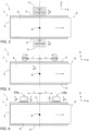
- Figure 3 shows vibrating equipment 1 provided with a pair 11 of rotating second vibration devices V2 which are arranged next to each other and are functioning as one unit.
- the second vibration devices V2 of the pair 11 have opposing rotation directions, whereby forces in the machine direction x are compensated.
- the functional and physical vibrating pair 11 may be arranged at a centre of gravity G. It is possible to arrange two disclosed vibrating pairs 11 on both sides of the vibrating body, as demonstrated in broken lines.
- two second vibrating devices V2a, V2b are arranged at a distance from each other and at a distance L from a center of gravity G of the vibrating equipment.
- the two second vibrating devices V2a, V2b are located at the equal distance L from the center of gravity G, forces other than desired forces causing lateral z-movement are eliminated.
- the rotating directions of the second vibrating devices may be the same and, further, it may be possible to use only one second vibrating device instead of two.
- the solution of Figure 5 differs from the solution of Figure 4 in that the rotation axes of the second vibrating devices V2a, V2b are horizontal.
- the vibrating deck is blind, i.e. it is without apertures.
- the vibrating equipment provided with the blind vibrating deck may be a feeder suitable for transporting a material.
- FIG. 6 shows a lateral vibrating unit 12 for producing lateral vibrations.
- the vibration unit 12 comprises at least one second vibrating device V2 for generating a vibrating movement.
- the second vibrating device V2 may comprise a rotating device 13 which is arranged to rotate an unbalance weight 14.
- the vibrating unit 12 further comprises mounting means 15 allowing the vibrating unit 12 to be mounted to a vibrating body 3 of the vibrating equipment.
- the mounting means 15 may comprise a mounting plate 16, which may be attached to an outer side surface, such as a side plate 5, of the vibrating body 3 by fastening elements 17.
- the vibrating unit 12 comprises power supply means 18 for transmitting necessary driving power.
- the mounting means 15 are formed so that they set a rotational axis of the second vibrating device V2 horizontally.
- Figure 7 shows an alternative lateral vibrating unit 12 which differs from the one shown in Figure 6 in that the rotating axis of the second vibrating device V2 is vertical.
- Figure 7 also shows a structure of a screening device, which comprises two vibrating screen decks 6a, 6b, one above the other.
- the upper screen deck 6a has larger screening apertures than the lower screen deck 6b.
- Figure 8 shows a lateral vibrating unit 12 comprising a linear vibrating device 19.
- the linear vibrating device 19 may comprise a reciprocating piston 20 or unbalance element. It is possible to utilize a hydraulic or electric percussion device for producing linear impacts i on the vibrating body 3.
- FIG. 9 demonstrates that the vibrating deck 6 may be turned R in a reciprocating manner around the machine-direction axis x.
- This turning motion R may be achieved by arranging the second vibrating devices V2a and V2b at an unequal vertical distance H from the center of gravity G.
- the generated turning R movement may further improve processing of problematic materials.
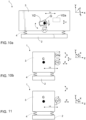
- Figure 10a shows that one single second vibrating device V2 is mounted in a side plate of a vibrating body at a centre of gravity G when seen from the side.
- An alternative angular mounting position of the second vibrating device V2 is shown in broken lines. It is possible to choose the angular position of the second vibrating device as desired.
- Another alternative is to arrange the second vibrating device at a distance from the centre of gravity G, as it is shown by reference numeral V2a.
- the second vibrating device V2a may be arranged at an x-direction distance L x from the centre of gravity G, or at an y-direction distance L y from the centre of gravity, or it may be arranged so that both distances L x and L y occur, which is the case in Figure 10b.
- Figure 10b shows that the second vibrating device V2 locates at a lateral distance L z from the centre of gravity G causing the desired lateral movement in the direction z.
- the vibrating body 3 may sway S relative to X-axis because the second vibrating device V2 or V2a is arranged at the distance L z and possibly also at the distance L y from the centre of gravity G.
- the swaying S makes the vibrating body to operate 3,5-dimensionally. Thanks to the swaying S the screening and processing of the material may be further improved.
- Figure 11 illustrates that the second vibrating device V2 may be arranged in an angular position relative to a vertical direction.
- Figures 10a, 10b and 11 one single second vibrating device may be used and it may comprise a rotating unbalance device.
- the drawings and the related description are only intended to illustrate the idea of the invention. In its details, the invention may vary within the scope of the claims.
Landscapes
- Engineering & Computer Science (AREA)
- Mechanical Engineering (AREA)
- Jigging Conveyors (AREA)
- Combined Means For Separation Of Solids (AREA)
Claims (13)
- Equipement vibrant qui est un crible vibrant ou un dispositif d'alimentation vibrant destiné au traitement d'un matériau de sol en vrac, comprenant :un châssis (2) ;au moins un corps vibrant (3) supporté sur le châssis (2) verticalement au moyen d'éléments de ressort (4), où le corps vibrant (3) est supporté au-dessus du châssis (2) et où les éléments de ressort (4) sont prévus entre le châssis (2) et le corps vibrant (3) ;au moins un étage vibrant (6) agencé dans le corps vibrant (3) ;une extrémité d'alimentation (7) et une extrémité d'évacuation (8) de l'étage vibrant (6) ;une direction de machine (x) de l'équipement vibrant (1), laquelle est déterminée par une direction de l'extrémité d'alimentation (7) à l'extrémité d'évacuation (8) et correspond à une direction de déplacement du matériau devant être traité ; etau moins un premier dispositif vibrant (V1) destiné à faire vibrer le corps vibrant (3) et à amener l'étage vibrant (6) à se déplacer dans une direction verticale (y) et dans la direction de machine (x) ;au moins un second dispositif vibrant indépendant (V2) afin d'amener le corps vibrant (3) à vibrer latéralement (z) par rapport à un plan xy,où le corps vibrant (3) comprend des plaques latérales (5), lesquelles sont dans la direction de machine (x) et délimitent le corps vibrant (3) dans la direction latérale (z),où le second dispositif vibrant (V2) comprend un dispositif rotatif (13) et au moins un poids de déséquilibre (14), lequel est entraîné en rotation par le dispositif rotatif (13),où les au moins un premier et second dispositifs vibrants sont configurés pour faire vibrer l'étage dans le corps vibrant dans des directions verticale et latérale simultanément,caractérisé en ce quele corps vibrant (3) est supporté au-dessus du châssis (2) et où les éléments de ressort (4) sont prévus entre le châssis (2) et le corps vibrant (3) etle au moins un second dispositif vibrant (V2) est monté contre une surface extérieure d'une plaque latérale (5) du corps vibrant (3), où l'axe de rotation du au moins un dispositif vibrant se trouve dans un plan xy.
- Equipement vibrant selon la revendication 1, caractérisé en ce que le au moins un second dispositif vibrant mentionné (V2) est physiquement et fonctionnellement indépendant du au moins un premier dispositif vibrant mentionné (V1).
- Equipement vibrant selon l'une quelconque des revendications précédentes, caractérisé en ce que
le second dispositif vibrant mentionné (V2) est agencé au niveau d'un centre de gravité (G) de l'équipement vibrant (1). - Equipement vibrant selon l'une quelconque des revendications précédentes, caractérisé en ce quel'équipement vibrant (1) comprend deux seconds dispositifs vibrants (V2) ; etles seconds dispositifs vibrants (V2) sont agencés au niveau d'un centre de gravité (G) et sur des côtés opposés du corps vibrant (3).
- Equipement vibrant selon l'une quelconque des revendications précédentes 1 et 2, caractérisé en ce que
l'équipement vibrant (1) comprend au moins deux seconds dispositifs vibrants (V2a, V2b) agencés à une certaine distance l'un de l'autre et à une distance égale (L) du centre de gravité (G). - Equipement vibrant selon l'une quelconque des revendications précédentes, caractérisé en ce quel'équipement vibrant (1) comprend deux seconds dispositifs vibrants (V2) ; etles seconds dispositifs vibrants (V2) comprennent un dispositif rotatif (13) et au moins un poids de déséquilibre (14), lequel est entraîné en rotation par le dispositif rotatif (13).
- Equipement vibrant selon la revendication 6, caractérisé en ce qu'une paire (11) de seconds dispositifs vibrants (V2) est agencée au moins sur un côté du corps vibrant (3) ; et
la paire (11) de seconds dispositifs vibrants (V2) est agencée au niveau du centre de gravité (G). - Equipement vibrant selon la revendication 6 ou 7, caractérisé en ce que des sens de rotation des deux seconds dispositifs vibrants (V2) sont opposés.
- Equipement vibrant selon l'une quelconque des revendications précédentes 1 et 2, caractérisé en ce queau moins deux seconds dispositifs vibrant (V2a, V2b) sont agencés dans le corps vibrant (3) à une hauteur verticale du centre de gravité (G) différente, grâce à quoi un couple autour d'un axe de direction de machine (x) est généré dans le corps vibrant (3) ; etun mouvement rotatif en va-et-vient (R) par rapport à l'axe de direction de machine (x) est généré dans l'étage vibrant (3) pendant le fonctionnement.
- Equipement vibrant selon la revendication 9, caractérisé en ce qu'une position du au moins un second dispositif vibrant mentionné (V2) est réglable.
- Equipement vibrant selon l'une quelconque des revendications précédentes, caractérisé en ce que l'équipement vibrant (1) est un crible vibrant doté d'au moins un étage de crible vibrant ; et l'étage de crible vibrant comprend plusieurs ouvertures de criblage.
- Equipement vibrant selon la revendication 11, caractérisé en ce que l'équipement vibrant (1) comprend au moins deux étages vibrants agencés l'un au-dessus de l'autre et dotés d'une taille d'ouverture mutuellement différente.
- Equipement vibrant selon l'une quelconque des revendications précédentes 1 à 10, caractérisé en ce que l'équipement vibrant (1) est un dispositif d'alimentation vibrant doté d'un étage vibrant plein.
Priority Applications (5)
| Application Number | Priority Date | Filing Date | Title |
|---|---|---|---|
| DK12198793.7T DK2745941T3 (da) | 2012-12-21 | 2012-12-21 | Vibrationsudstyr til bearbejdning af materiale |
| FIEP12198793.7T FI2745941T3 (fi) | 2012-12-21 | 2012-12-21 | Tärylaitteisto aineksen käsittelemistä varten |
| EP12198793.7A EP2745941B1 (fr) | 2012-12-21 | 2012-12-21 | Équipement vibrant pour le traitement de matériaux |
| PCT/EP2013/074702 WO2014095259A1 (fr) | 2012-12-20 | 2013-11-26 | Équipement vibrant et procédé de traitement de matériau |
| US14/653,968 US9649665B2 (en) | 2012-12-20 | 2013-11-26 | Vibrating equipment and method of processing material |
Applications Claiming Priority (1)
| Application Number | Priority Date | Filing Date | Title |
|---|---|---|---|
| EP12198793.7A EP2745941B1 (fr) | 2012-12-21 | 2012-12-21 | Équipement vibrant pour le traitement de matériaux |
Publications (2)
| Publication Number | Publication Date |
|---|---|
| EP2745941A1 EP2745941A1 (fr) | 2014-06-25 |
| EP2745941B1 true EP2745941B1 (fr) | 2024-07-24 |
Family
ID=47678502
Family Applications (1)
| Application Number | Title | Priority Date | Filing Date |
|---|---|---|---|
| EP12198793.7A Active EP2745941B1 (fr) | 2012-12-20 | 2012-12-21 | Équipement vibrant pour le traitement de matériaux |
Country Status (5)
| Country | Link |
|---|---|
| US (1) | US9649665B2 (fr) |
| EP (1) | EP2745941B1 (fr) |
| DK (1) | DK2745941T3 (fr) |
| FI (1) | FI2745941T3 (fr) |
| WO (1) | WO2014095259A1 (fr) |
Families Citing this family (6)
| Publication number | Priority date | Publication date | Assignee | Title |
|---|---|---|---|---|
| JP7349777B2 (ja) * | 2018-05-30 | 2023-09-25 | シンフォニアテクノロジー株式会社 | 材料積層装置 |
| JP2019205979A (ja) * | 2018-05-30 | 2019-12-05 | シンフォニアテクノロジー株式会社 | 材料積層装置 |
| US11020768B2 (en) * | 2019-02-04 | 2021-06-01 | Superior Industries, Inc. | Vibratory classifiers |
| FR3101865B1 (fr) * | 2019-10-09 | 2021-10-29 | Sinex Ind | Support vibrant pour transfert de produits a double sens et procede de conduite dudit support vibrant double sens. |
| CN112657832B (zh) * | 2021-01-15 | 2021-12-10 | 徐永楠 | 一种水利工程用筛沙装置 |
| CN113198724A (zh) * | 2021-04-28 | 2021-08-03 | 江西千彩水晶有限公司 | 一种水晶珠坯筛选装置 |
Citations (1)
| Publication number | Priority date | Publication date | Assignee | Title |
|---|---|---|---|---|
| US4482455A (en) * | 1981-10-16 | 1984-11-13 | Humphrey Cecil T | Dual frequency vibratory screen for classifying granular material |
Family Cites Families (12)
| Publication number | Priority date | Publication date | Assignee | Title |
|---|---|---|---|---|
| US2236341A (en) * | 1937-01-29 | 1941-03-25 | George E Markley | Vibratory material handling screen mechanism |
| US2874841A (en) * | 1953-12-21 | 1959-02-24 | Albin K Peterson | Oscillatable separator means |
| GB944950A (en) * | 1960-12-15 | 1963-12-18 | Scragg Edgar Peter | Improvements in or relating to vibrating screens |
| US3796299A (en) * | 1971-07-08 | 1974-03-12 | Gen Kinematics Corp | Vibratory material handling device with variable force application |
| DD151882A1 (de) * | 1979-11-08 | 1981-11-11 | Dressler Ernst Heinrich | Mehrdecksiebmaschine |
| FR2570300B3 (fr) * | 1984-09-20 | 1987-01-30 | Lebras Jean Yves | Dispositif de commande d'un tamis a secousses pour le calibrage, notamment de fruits et legumes, et installations mettant en oeuvre un tel tamis |
| FR2604376A1 (fr) * | 1986-09-26 | 1988-04-01 | Europ Vibration | Perfectionnements aux vibrateurs a balourd rotatif |
| US5265730A (en) * | 1992-04-06 | 1993-11-30 | Sweco, Incorporated | Vibratory screen separator |
| CA2347947C (fr) * | 1998-10-21 | 2006-05-09 | Manorex Limited | Ensemble vibreur |
| US7905358B2 (en) * | 2006-07-07 | 2011-03-15 | Alliant Techsystems Inc. | Apparatus and methods for filtering granular solid material |
| GB2461727B (en) * | 2008-07-10 | 2012-06-13 | United Wire Ltd | Improved sifting screen |
| CH700371B1 (fr) | 2009-02-05 | 2013-11-15 | Asyril Sa | Système d'alimentation en composants. |
-
2012
- 2012-12-21 DK DK12198793.7T patent/DK2745941T3/da active
- 2012-12-21 FI FIEP12198793.7T patent/FI2745941T3/fi active
- 2012-12-21 EP EP12198793.7A patent/EP2745941B1/fr active Active
-
2013
- 2013-11-26 WO PCT/EP2013/074702 patent/WO2014095259A1/fr not_active Ceased
- 2013-11-26 US US14/653,968 patent/US9649665B2/en active Active
Patent Citations (1)
| Publication number | Priority date | Publication date | Assignee | Title |
|---|---|---|---|---|
| US4482455A (en) * | 1981-10-16 | 1984-11-13 | Humphrey Cecil T | Dual frequency vibratory screen for classifying granular material |
Also Published As
| Publication number | Publication date |
|---|---|
| DK2745941T3 (da) | 2024-09-23 |
| US20150353290A1 (en) | 2015-12-10 |
| WO2014095259A1 (fr) | 2014-06-26 |
| US9649665B2 (en) | 2017-05-16 |
| EP2745941A1 (fr) | 2014-06-25 |
| FI2745941T3 (fi) | 2024-09-20 |
Similar Documents
| Publication | Publication Date | Title |
|---|---|---|
| US9649665B2 (en) | Vibrating equipment and method of processing material | |
| CN110404766B (zh) | 一种灵活的水平振动筛 | |
| CN104001665B (zh) | 一种带式直线振动筛 | |
| CN105689257B (zh) | 一种模块式变跨距变振幅大型振动筛 | |
| US20130092607A1 (en) | Method and device for screening materials, such as aggregates and/or soils | |
| JP2012206015A (ja) | 破砕機 | |
| CN203076195U (zh) | 一种直线振动筛分机 | |
| CN114210559B (zh) | 砂石骨料生产系统 | |
| CN210449823U (zh) | 一种灵活的水平振动筛 | |
| CN104492525A (zh) | 一种柔性传动破碎机 | |
| CN102601042A (zh) | 一种平动椭圆振动筛 | |
| KR101805969B1 (ko) | 벌크 재료의 분류 방법 및 그 장치 | |
| JPH09150117A (ja) | 選別機械 | |
| EP2318153B1 (fr) | Ensemble vibrant, appareil de traitement de matière minérale et procédé de déplacement d'un dispositif de traitement d'un appareil de traitement de matière minérale | |
| CN106622940A (zh) | 一种用于矿石颗粒筛选的筛选系统 | |
| EP0272157A2 (fr) | Appareil de broyage | |
| CN205599493U (zh) | 一种模块式变跨距变振幅大型振动筛 | |
| CN213650921U (zh) | 均匀出料的振动放矿机 | |
| RU2621357C1 (ru) | Вибрационная щековая дробилка | |
| CN203862543U (zh) | 一种带式直线振动筛 | |
| CN202527364U (zh) | 一种带均匀进料装置的回转分级筛 | |
| CN114700161A (zh) | 一种固定式给料破碎机组设备及给料方法 | |
| CN107716292A (zh) | 一种基于电路控制的新型高频振动筛 | |
| CN223812996U (zh) | 一种砂石送料振动给料机 | |
| EP4385631A1 (fr) | Un tamiseur |
Legal Events
| Date | Code | Title | Description |
|---|---|---|---|
| PUAI | Public reference made under article 153(3) epc to a published international application that has entered the european phase |
Free format text: ORIGINAL CODE: 0009012 |
|
| 17P | Request for examination filed |
Effective date: 20121221 |
|
| AK | Designated contracting states |
Kind code of ref document: A1 Designated state(s): AL AT BE BG CH CY CZ DE DK EE ES FI FR GB GR HR HU IE IS IT LI LT LU LV MC MK MT NL NO PL PT RO RS SE SI SK SM TR |
|
| AX | Request for extension of the european patent |
Extension state: BA ME |
|
| R17P | Request for examination filed (corrected) |
Effective date: 20150105 |
|
| RBV | Designated contracting states (corrected) |
Designated state(s): AL AT BE BG CH CY CZ DE DK EE ES FI FR GB GR HR HU IE IS IT LI LT LU LV MC MK MT NL NO PL PT RO RS SE SI SK SM TR |
|
| STAA | Information on the status of an ep patent application or granted ep patent |
Free format text: STATUS: EXAMINATION IS IN PROGRESS |
|
| 17Q | First examination report despatched |
Effective date: 20180219 |
|
| P01 | Opt-out of the competence of the unified patent court (upc) registered |
Effective date: 20230603 |
|
| REG | Reference to a national code |
Ref country code: DE Free format text: PREVIOUS MAIN CLASS: B07B0001360000 Ipc: B07B0001420000 Ref country code: DE Ref legal event code: R079 Ref document number: 602012080953 Country of ref document: DE Free format text: PREVIOUS MAIN CLASS: B07B0001360000 Ipc: B07B0001420000 |
|
| RIC1 | Information provided on ipc code assigned before grant |
Ipc: B07B 1/40 20060101ALI20240103BHEP Ipc: B65G 27/32 20060101ALI20240103BHEP Ipc: B07B 1/36 20060101ALI20240103BHEP Ipc: B07B 1/42 20060101AFI20240103BHEP |
|
| GRAP | Despatch of communication of intention to grant a patent |
Free format text: ORIGINAL CODE: EPIDOSNIGR1 |
|
| STAA | Information on the status of an ep patent application or granted ep patent |
Free format text: STATUS: GRANT OF PATENT IS INTENDED |
|
| INTG | Intention to grant announced |
Effective date: 20240214 |
|
| GRAS | Grant fee paid |
Free format text: ORIGINAL CODE: EPIDOSNIGR3 |
|
| GRAA | (expected) grant |
Free format text: ORIGINAL CODE: 0009210 |
|
| STAA | Information on the status of an ep patent application or granted ep patent |
Free format text: STATUS: THE PATENT HAS BEEN GRANTED |
|
| AK | Designated contracting states |
Kind code of ref document: B1 Designated state(s): AL AT BE BG CH CY CZ DE DK EE ES FI FR GB GR HR HU IE IS IT LI LT LU LV MC MK MT NL NO PL PT RO RS SE SI SK SM TR |
|
| REG | Reference to a national code |
Ref country code: GB Ref legal event code: FG4D |
|
| REG | Reference to a national code |
Ref country code: CH Ref legal event code: EP |
|
| REG | Reference to a national code |
Ref country code: DE Ref legal event code: R096 Ref document number: 602012080953 Country of ref document: DE |
|
| REG | Reference to a national code |
Ref country code: IE Ref legal event code: FG4D |
|
| REG | Reference to a national code |
Ref country code: FI Ref legal event code: FGE |
|
| REG | Reference to a national code |
Ref country code: DK Ref legal event code: T3 Effective date: 20240917 |
|
| REG | Reference to a national code |
Ref country code: SE Ref legal event code: TRGR |
|
| REG | Reference to a national code |
Ref country code: LT Ref legal event code: MG9D |
|
| PG25 | Lapsed in a contracting state [announced via postgrant information from national office to epo] |
Ref country code: PT Free format text: LAPSE BECAUSE OF FAILURE TO SUBMIT A TRANSLATION OF THE DESCRIPTION OR TO PAY THE FEE WITHIN THE PRESCRIBED TIME-LIMIT Effective date: 20241125 |
|
| REG | Reference to a national code |
Ref country code: AT Ref legal event code: MK05 Ref document number: 1705839 Country of ref document: AT Kind code of ref document: T Effective date: 20240724 |
|
| PG25 | Lapsed in a contracting state [announced via postgrant information from national office to epo] |
Ref country code: NL Free format text: LAPSE BECAUSE OF FAILURE TO SUBMIT A TRANSLATION OF THE DESCRIPTION OR TO PAY THE FEE WITHIN THE PRESCRIBED TIME-LIMIT Effective date: 20240724 |
|
| PG25 | Lapsed in a contracting state [announced via postgrant information from national office to epo] |
Ref country code: PT Free format text: LAPSE BECAUSE OF FAILURE TO SUBMIT A TRANSLATION OF THE DESCRIPTION OR TO PAY THE FEE WITHIN THE PRESCRIBED TIME-LIMIT Effective date: 20241125 Ref country code: NL Free format text: LAPSE BECAUSE OF FAILURE TO SUBMIT A TRANSLATION OF THE DESCRIPTION OR TO PAY THE FEE WITHIN THE PRESCRIBED TIME-LIMIT Effective date: 20240724 |
|
| PGFP | Annual fee paid to national office [announced via postgrant information from national office to epo] |
Ref country code: DE Payment date: 20241029 Year of fee payment: 13 |
|
| PG25 | Lapsed in a contracting state [announced via postgrant information from national office to epo] |
Ref country code: PL Free format text: LAPSE BECAUSE OF FAILURE TO SUBMIT A TRANSLATION OF THE DESCRIPTION OR TO PAY THE FEE WITHIN THE PRESCRIBED TIME-LIMIT Effective date: 20240724 Ref country code: GR Free format text: LAPSE BECAUSE OF FAILURE TO SUBMIT A TRANSLATION OF THE DESCRIPTION OR TO PAY THE FEE WITHIN THE PRESCRIBED TIME-LIMIT Effective date: 20241025 |
|
| PGFP | Annual fee paid to national office [announced via postgrant information from national office to epo] |
Ref country code: GB Payment date: 20241104 Year of fee payment: 13 |
|
| PG25 | Lapsed in a contracting state [announced via postgrant information from national office to epo] |
Ref country code: BG Free format text: LAPSE BECAUSE OF FAILURE TO SUBMIT A TRANSLATION OF THE DESCRIPTION OR TO PAY THE FEE WITHIN THE PRESCRIBED TIME-LIMIT Effective date: 20240724 |
|
| PGFP | Annual fee paid to national office [announced via postgrant information from national office to epo] |
Ref country code: FR Payment date: 20241121 Year of fee payment: 13 |
|
| PG25 | Lapsed in a contracting state [announced via postgrant information from national office to epo] |
Ref country code: LV Free format text: LAPSE BECAUSE OF FAILURE TO SUBMIT A TRANSLATION OF THE DESCRIPTION OR TO PAY THE FEE WITHIN THE PRESCRIBED TIME-LIMIT Effective date: 20240724 |
|
| PG25 | Lapsed in a contracting state [announced via postgrant information from national office to epo] |
Ref country code: AT Free format text: LAPSE BECAUSE OF FAILURE TO SUBMIT A TRANSLATION OF THE DESCRIPTION OR TO PAY THE FEE WITHIN THE PRESCRIBED TIME-LIMIT Effective date: 20240724 Ref country code: IS Free format text: LAPSE BECAUSE OF FAILURE TO SUBMIT A TRANSLATION OF THE DESCRIPTION OR TO PAY THE FEE WITHIN THE PRESCRIBED TIME-LIMIT Effective date: 20241124 |
|
| PG25 | Lapsed in a contracting state [announced via postgrant information from national office to epo] |
Ref country code: HR Free format text: LAPSE BECAUSE OF FAILURE TO SUBMIT A TRANSLATION OF THE DESCRIPTION OR TO PAY THE FEE WITHIN THE PRESCRIBED TIME-LIMIT Effective date: 20240724 |
|
| PG25 | Lapsed in a contracting state [announced via postgrant information from national office to epo] |
Ref country code: RS Free format text: LAPSE BECAUSE OF FAILURE TO SUBMIT A TRANSLATION OF THE DESCRIPTION OR TO PAY THE FEE WITHIN THE PRESCRIBED TIME-LIMIT Effective date: 20241024 Ref country code: ES Free format text: LAPSE BECAUSE OF FAILURE TO SUBMIT A TRANSLATION OF THE DESCRIPTION OR TO PAY THE FEE WITHIN THE PRESCRIBED TIME-LIMIT Effective date: 20240724 |
|
| PGFP | Annual fee paid to national office [announced via postgrant information from national office to epo] |
Ref country code: SE Payment date: 20241114 Year of fee payment: 13 |
|
| PG25 | Lapsed in a contracting state [announced via postgrant information from national office to epo] |
Ref country code: RS Free format text: LAPSE BECAUSE OF FAILURE TO SUBMIT A TRANSLATION OF THE DESCRIPTION OR TO PAY THE FEE WITHIN THE PRESCRIBED TIME-LIMIT Effective date: 20241024 Ref country code: PL Free format text: LAPSE BECAUSE OF FAILURE TO SUBMIT A TRANSLATION OF THE DESCRIPTION OR TO PAY THE FEE WITHIN THE PRESCRIBED TIME-LIMIT Effective date: 20240724 Ref country code: LV Free format text: LAPSE BECAUSE OF FAILURE TO SUBMIT A TRANSLATION OF THE DESCRIPTION OR TO PAY THE FEE WITHIN THE PRESCRIBED TIME-LIMIT Effective date: 20240724 Ref country code: IS Free format text: LAPSE BECAUSE OF FAILURE TO SUBMIT A TRANSLATION OF THE DESCRIPTION OR TO PAY THE FEE WITHIN THE PRESCRIBED TIME-LIMIT Effective date: 20241124 Ref country code: HR Free format text: LAPSE BECAUSE OF FAILURE TO SUBMIT A TRANSLATION OF THE DESCRIPTION OR TO PAY THE FEE WITHIN THE PRESCRIBED TIME-LIMIT Effective date: 20240724 Ref country code: GR Free format text: LAPSE BECAUSE OF FAILURE TO SUBMIT A TRANSLATION OF THE DESCRIPTION OR TO PAY THE FEE WITHIN THE PRESCRIBED TIME-LIMIT Effective date: 20241025 Ref country code: ES Free format text: LAPSE BECAUSE OF FAILURE TO SUBMIT A TRANSLATION OF THE DESCRIPTION OR TO PAY THE FEE WITHIN THE PRESCRIBED TIME-LIMIT Effective date: 20240724 Ref country code: BG Free format text: LAPSE BECAUSE OF FAILURE TO SUBMIT A TRANSLATION OF THE DESCRIPTION OR TO PAY THE FEE WITHIN THE PRESCRIBED TIME-LIMIT Effective date: 20240724 Ref country code: AT Free format text: LAPSE BECAUSE OF FAILURE TO SUBMIT A TRANSLATION OF THE DESCRIPTION OR TO PAY THE FEE WITHIN THE PRESCRIBED TIME-LIMIT Effective date: 20240724 |
|
| PG25 | Lapsed in a contracting state [announced via postgrant information from national office to epo] |
Ref country code: RO Free format text: LAPSE BECAUSE OF FAILURE TO SUBMIT A TRANSLATION OF THE DESCRIPTION OR TO PAY THE FEE WITHIN THE PRESCRIBED TIME-LIMIT Effective date: 20240724 Ref country code: SM Free format text: LAPSE BECAUSE OF FAILURE TO SUBMIT A TRANSLATION OF THE DESCRIPTION OR TO PAY THE FEE WITHIN THE PRESCRIBED TIME-LIMIT Effective date: 20240724 |
|
| PG25 | Lapsed in a contracting state [announced via postgrant information from national office to epo] |
Ref country code: EE Free format text: LAPSE BECAUSE OF FAILURE TO SUBMIT A TRANSLATION OF THE DESCRIPTION OR TO PAY THE FEE WITHIN THE PRESCRIBED TIME-LIMIT Effective date: 20240724 |
|
| PG25 | Lapsed in a contracting state [announced via postgrant information from national office to epo] |
Ref country code: CZ Free format text: LAPSE BECAUSE OF FAILURE TO SUBMIT A TRANSLATION OF THE DESCRIPTION OR TO PAY THE FEE WITHIN THE PRESCRIBED TIME-LIMIT Effective date: 20240724 |
|
| REG | Reference to a national code |
Ref country code: DE Ref legal event code: R097 Ref document number: 602012080953 Country of ref document: DE |
|
| PG25 | Lapsed in a contracting state [announced via postgrant information from national office to epo] |
Ref country code: SK Free format text: LAPSE BECAUSE OF FAILURE TO SUBMIT A TRANSLATION OF THE DESCRIPTION OR TO PAY THE FEE WITHIN THE PRESCRIBED TIME-LIMIT Effective date: 20240724 Ref country code: IT Free format text: LAPSE BECAUSE OF FAILURE TO SUBMIT A TRANSLATION OF THE DESCRIPTION OR TO PAY THE FEE WITHIN THE PRESCRIBED TIME-LIMIT Effective date: 20240724 |
|
| PLBE | No opposition filed within time limit |
Free format text: ORIGINAL CODE: 0009261 |
|
| STAA | Information on the status of an ep patent application or granted ep patent |
Free format text: STATUS: NO OPPOSITION FILED WITHIN TIME LIMIT |
|
| 26N | No opposition filed |
Effective date: 20250425 |
|
| PG25 | Lapsed in a contracting state [announced via postgrant information from national office to epo] |
Ref country code: MC Free format text: LAPSE BECAUSE OF FAILURE TO SUBMIT A TRANSLATION OF THE DESCRIPTION OR TO PAY THE FEE WITHIN THE PRESCRIBED TIME-LIMIT Effective date: 20240724 |
|
| PG25 | Lapsed in a contracting state [announced via postgrant information from national office to epo] |
Ref country code: FI Free format text: LAPSE BECAUSE OF NON-PAYMENT OF DUE FEES Effective date: 20241221 |
|
| REG | Reference to a national code |
Ref country code: DK Ref legal event code: EBP Effective date: 20241231 |
|
| REG | Reference to a national code |
Ref country code: CH Ref legal event code: PL |
|
| PG25 | Lapsed in a contracting state [announced via postgrant information from national office to epo] |
Ref country code: LU Free format text: LAPSE BECAUSE OF NON-PAYMENT OF DUE FEES Effective date: 20241221 |
|
| REG | Reference to a national code |
Ref country code: BE Ref legal event code: MM Effective date: 20241231 |
|
| PG25 | Lapsed in a contracting state [announced via postgrant information from national office to epo] |
Ref country code: NO Free format text: LAPSE BECAUSE OF NON-PAYMENT OF DUE FEES Effective date: 20241231 |
|
| PG25 | Lapsed in a contracting state [announced via postgrant information from national office to epo] |
Ref country code: BE Free format text: LAPSE BECAUSE OF NON-PAYMENT OF DUE FEES Effective date: 20241231 |
|
| PG25 | Lapsed in a contracting state [announced via postgrant information from national office to epo] |
Ref country code: CH Free format text: LAPSE BECAUSE OF NON-PAYMENT OF DUE FEES Effective date: 20241231 |
|
| PG25 | Lapsed in a contracting state [announced via postgrant information from national office to epo] |
Ref country code: IE Free format text: LAPSE BECAUSE OF NON-PAYMENT OF DUE FEES Effective date: 20241221 |
|
| PG25 | Lapsed in a contracting state [announced via postgrant information from national office to epo] |
Ref country code: DK Free format text: LAPSE BECAUSE OF NON-PAYMENT OF DUE FEES Effective date: 20241231 |
|
| PG25 | Lapsed in a contracting state [announced via postgrant information from national office to epo] |
Ref country code: CY Free format text: LAPSE BECAUSE OF FAILURE TO SUBMIT A TRANSLATION OF THE DESCRIPTION OR TO PAY THE FEE WITHIN THE PRESCRIBED TIME-LIMIT Effective date: 20240724 |