EP2745949A1 - Richtmaschine - Google Patents
Richtmaschine Download PDFInfo
- Publication number
- EP2745949A1 EP2745949A1 EP12425201.6A EP12425201A EP2745949A1 EP 2745949 A1 EP2745949 A1 EP 2745949A1 EP 12425201 A EP12425201 A EP 12425201A EP 2745949 A1 EP2745949 A1 EP 2745949A1
- Authority
- EP
- European Patent Office
- Prior art keywords
- roll shaft
- straightening machine
- defining
- machine according
- rotation
- Prior art date
- Legal status (The legal status is an assumption and is not a legal conclusion. Google has not performed a legal analysis and makes no representation as to the accuracy of the status listed.)
- Withdrawn
Links
- 238000005452 bending Methods 0.000 claims abstract description 38
- 230000000712 assembly Effects 0.000 claims abstract description 11
- 238000000429 assembly Methods 0.000 claims abstract description 11
- 230000008878 coupling Effects 0.000 claims description 13
- 238000010168 coupling process Methods 0.000 claims description 13
- 238000005859 coupling reaction Methods 0.000 claims description 13
- 230000000295 complement effect Effects 0.000 claims description 8
- 210000003414 extremity Anatomy 0.000 description 7
- 230000007547 defect Effects 0.000 description 3
- 230000033001 locomotion Effects 0.000 description 3
- 125000006850 spacer group Chemical group 0.000 description 3
- 238000005098 hot rolling Methods 0.000 description 2
- 238000005461 lubrication Methods 0.000 description 2
- 239000002184 metal Substances 0.000 description 2
- 230000005540 biological transmission Effects 0.000 description 1
- 238000005097 cold rolling Methods 0.000 description 1
- 230000003750 conditioning effect Effects 0.000 description 1
- 238000001816 cooling Methods 0.000 description 1
- 238000006073 displacement reaction Methods 0.000 description 1
- 230000000694 effects Effects 0.000 description 1
- 210000003141 lower extremity Anatomy 0.000 description 1
- 238000005259 measurement Methods 0.000 description 1
- 238000000926 separation method Methods 0.000 description 1
- 238000005728 strengthening Methods 0.000 description 1
Images



Classifications
-
- B—PERFORMING OPERATIONS; TRANSPORTING
- B21—MECHANICAL METAL-WORKING WITHOUT ESSENTIALLY REMOVING MATERIAL; PUNCHING METAL
- B21D—WORKING OR PROCESSING OF SHEET METAL OR METAL TUBES, RODS OR PROFILES WITHOUT ESSENTIALLY REMOVING MATERIAL; PUNCHING METAL
- B21D1/00—Straightening, restoring form or removing local distortions of sheet metal or specific articles made therefrom; Stretching sheet metal combined with rolling
- B21D1/05—Stretching combined with rolling
-
- B—PERFORMING OPERATIONS; TRANSPORTING
- B21—MECHANICAL METAL-WORKING WITHOUT ESSENTIALLY REMOVING MATERIAL; PUNCHING METAL
- B21D—WORKING OR PROCESSING OF SHEET METAL OR METAL TUBES, RODS OR PROFILES WITHOUT ESSENTIALLY REMOVING MATERIAL; PUNCHING METAL
- B21D3/00—Straightening or restoring form of metal rods, metal tubes, metal profiles, or specific articles made therefrom, whether or not in combination with sheet metal parts
- B21D3/02—Straightening or restoring form of metal rods, metal tubes, metal profiles, or specific articles made therefrom, whether or not in combination with sheet metal parts by rollers
- B21D3/05—Straightening or restoring form of metal rods, metal tubes, metal profiles, or specific articles made therefrom, whether or not in combination with sheet metal parts by rollers arranged on axes rectangular to the path of the work
-
- B—PERFORMING OPERATIONS; TRANSPORTING
- B22—CASTING; POWDER METALLURGY
- B22D—CASTING OF METALS; CASTING OF OTHER SUBSTANCES BY THE SAME PROCESSES OR DEVICES
- B22D11/00—Continuous casting of metals, i.e. casting in indefinite lengths
- B22D11/12—Accessories for subsequent treating or working cast stock in situ
- B22D11/1226—Accessories for subsequent treating or working cast stock in situ for straightening strands
Definitions
- the invention relates to a machine for straightening long metal products such as beams or rails.
- Leveling devices known as levelers or strengthening machines, are used to remove flatness defects in long products following hot or cold rolling. After hot rolling, cooling and conditioning phases, the rolled products may have straightness, bending of web or out of square defects. These geometric defects visibly affect rolled products.
- Levelers with multiple rollers arranged such that they overlap, establishing an undulating route for the long product, which is then subjected to bending effects in alternating directions, are used to level such rolled long metal products.
- a motorized drive system makes it possible to actuate the rollers in rotation and, by friction, to move the long product forward at a given speed.
- document US 5 327 760 discloses in one embodiment a straightening machine wherein the compensating rotation of the rolls shaft is realized by use of contact between flat and convex surfaces 20 and 21. The intersection between these two surfaces is a line, and the entire load of the anti bending rotation is distributed on this contact line.
- this induces an increased wearing of the mechanical parts and implies frequent changes of these worn parts, which leads to productivity diminution as the straightening machine can not be used during this repairing time.
- An objective of the present invention is to solve the above mentioned problems.
- a straightening machine comprising a frame supporting housings, each housing receiving a roll shafts rotatable about its axis, the straightening machine further comprising:
- the straightening machine further comprises:
- the assemblies are designed and are located such that in a longitudinal cross section of the roll shaft, the contact line of each assembly is respectively part of a first and a second virtual circle, first and second virtual circles having different radii and having the same virtual centre, the roll shaft housing being rotatable about said centre for correction of the bending induced by the product to be straighten,
- the guided elements are fixedly attached to one of the roll housings and rotate with the roll shaft housing during anti-bending rotation,
- each guide is attached with a corresponding guided element by means of spring screws received in a recesses defined in each guide and in each guided element, the spring screw allowing rotation of the guided element relative to the guide during anti-bending rotation of the roll shaft housing,
- each recess of each guided element receiving a spring screw has a diameter greater than the diameter of the spring screw such that a clearance exists between the spring screw and the wall of the recess of the guided element, whereas the spring screw is fixedly screwed in the recess of the corresponding guide, the clearance allowing rotation of each guided element relative to the convex guide during anti-bending rotation of the roll shaft housing,
- the means for rotating the roll shaft housing define a first contact surface between a convex and a concave surface, and wherein in a longitudinal cross section of the roll shaft housing, the contact surface is a contact line part of virtual circle, the centre of this circle being also point P,
- the means for rotating the rolls shaft housing comprises a second contact surface between a convex and a concave surface
- the means for rotating the roll shaft housing comprise:
- the means for displacing the roll shaft housing further comprise at least two driving bolts, each driving bolt cooperating with a screw piston for translating each screw piston, and each driving bolt having an external screwed portion,
- the means for displacing the roll shaft housing further comprise at least two aligned driving shafts, each driving shaft engaging with the external screwed portion of a driving bolt for rotating each screw piston,
- each driving shaft has a geared extremity and wherein a gear coupling system is interposed between the two driving shafts, the gear coupling system being displaceable between:
- the means for displacing the roll shaft housing further comprise a shift fork driven by a cylinder, said shift fork displacing the gear coupling system between the first and the second position and vice-versa,
- the straightening machine comprises at least two arms, each arm defining a recess, each recess receiving a screw piston end and a sliding element.
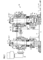
- Figure 1 is a longitudinal cross section of a roll shaft of leveling machine according to the invention
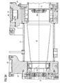
- FIG. 2 is an enlargement of figure 1 showing the rotating driving system according to the invention
- Figure 3a is an enlargement of figure 1 showing the roll shaft and the rotations guides;
- Figure 3b is a detailed view of figure 1 showing only the rotation guides according to the invention.
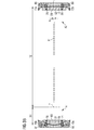
- Figure 4 is an horizontal cross section of figure 1 showing the driving system used for rotating the roll shaft according to the invention
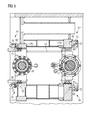
- Figure 5 is a top view of figure 1 ;
- Figures 6a to 6e are schematic views of a straightening machine according to the invention.
- FIG. 1 shows partially the housing 12 of straightening machine 10.
- a roll shaft 14 is located in the housing 10 and can rotate about its longitudinal axis X thanks to a plurality of bearings interposed between the roll shaft and the housing 12.
- the roll shaft receives at one of its extremity a straightening roller 20 comprising two straightening disks 16 and 18.
- the roll straightening rollers 20 is supported in a cantilever fashion outside the housing 14.
- the straightening roll 20 is designed to act on the product to be leveled.
- a motor 34 and a gear assembly 32 are provided for driving the rotation of the roll shaft 14.
- a straightening machine comprises a plurality of roll shafts and rollers defining a path for the product to be leveled.
- the housing further comprises two supporting arms 22 and 24, left and right arm when watching figure 1 , extending transversally to the roll shaft axis.
- the two arms 22 and 24 extend upward.
- the two arms 22 and 24 are horizontally spaced apart one from the other.
- the left (or first) arm 22 defines a recess receiving a convex sliding element 26 and the lower end 28e of a screw piston 28.
- the sliding element 26 has a convex surface and a flat surface. The flat surface is directed toward and lies on the left arm of the straightening machine whereas the convex surface of the sliding element 26 is directed toward the screw piston end 28e.
- the screw piston end 28e is linked to the left arm by mean of an annular flange 30 having a U shape.
- a chock ring 32 is interposed between the screw piston end 28 and the flange 30.
- the screw piston end 28 has a cylindrical shape defining a concave extremity which is complementary with the convex sliding element 26.
- This lower end 28e of the screw piston has a diameter higher than the diameter of the body of the screw piston 28. This creates a shoulder where the chock ring 32 is supported.
- the contact surface S3 of the convex sliding element 26 and of the concave screw piston end 28e is a line part of a virtual circle C3.
- the centre of the circle C3 is superimposed with the anti-bending center of rotation of the roll shaft. In other words, the horizontal transverse anti-bending axis passes through the center of the circle C3.
- the body of the left screw piston 28 has a screwed portion 28b cooperating with a driving bolt 38.
- the rotation of the driving bolt 38 provokes the translation of the screw piston 28.
- the driving bolt 38 has a cross-shape section and lies on a horizontal roll bearing 40 allowing its rotation about the axis of the screw piston 28.
- the driving bolt 38 also comprises an external thread for its cooperation with a worm screw, as will be explained latter.
- the driving bolt 38 is maintained in position by means of a second flange 42.
- a portion of the screw piston extends upwardly beyond the second flange 42 and is covered by a cap 44.
- the cap defines an oil inlet for lubrication of the assembly.
- the left screw piston 28 is designed to push on the sliding element 32 which in turn pushes on the housing 12 of the roll shaft 14 of the straightening machine 10 provoking the corrective bending of the roll shaft.
- the right (or second) supporting arm 24 also defines a recess receiving a spacer 46 on which lies a load sensors 48.
- the spacer is used to correct the flatness default of the downward surface of the recess which could influence the load measurement.
- the recess also receives another spacer 49 which in turn supports a second convex sliding element 50 and the lower end 52a of a right (or second) convex screw piston 52.
- the sliding element 50 and the lower end (or extremity) 52a define a contact surface S4.
- the right screw piston end 52 is fixedly secured to the right arm by mean of screwed ring flange 54.
- a chock ring 56 is interposed between the end (or lower extremity) of the right screw piston 24 and the flange 54.
- the lower end 52a of the right screw piston 52 has a cylindrical shape with a concave extremity which is complementary with the right convex sliding element 50.
- This lower end 52a of the right screw piston 52 has a diameter higher than the diameter of the body of the screw piston. This creates a shoulder where the chock ring 56 is located.
- the body of the right screw piston 52 has an external screwed portion 52b cooperating with a right driving bolt 58.
- the rotation of the right driving bolt 58 provokes the translation of the screw piston 52.
- the driving bolt has a cross-shape and cooperates with an upward horizontal roll bearing 60 allowing its rotation about the axis of the right screw piston 52.
- the right driving bolt 58 also comprises an external thread 58a for its cooperation with a worm screw, as will be explained latter.
- the right driving bolt 58 is maintained in position by means of a second flange 62.
- a portion of the right screw piston 52 extends upwardly beyond the second flange 62 and is covered by a cap 64.
- the cap defines an oil inlet for lubrication of the assembly.
- the right screw piston 52 is designed to push on the right sliding element 50 which in turn pushes on the housing of the roll shaft of the straightening machine provoking translation of the roll shaft, as this will be explained in more details under.
- the straightening machine further comprises at least four guides 66 ,66', 68 and 68' for guiding the rotation of the roll shaft 14 about a virtual axis P transverse to the roll shaft axis X.
- the four guides 66, 66', 68 and 68 are fixedly connected to the frame 120 of the straightening machine and are horizontally spaced apart one from the other.
- Each guide 66, 66', 68 or 68' defines a convex surface which cooperates with a concave surface defined by a guided element 70, 70', 72, 72' of the roll shaft housing 12.
- elements 70, 70', 72, 72' are fixedly attached to the roll shaft housing 12 and move with this housing.
- elements 70, 70', 72 and 72' are sliding blocks of the roll shaft housing 12 extending from the roll shaft housing.
- Each sliding block 70, 70', 72 or 72' rotates with the housing guided by the corresponding guide 66, 66', 68 or 68.
- Each concave surface of each sliding block 70, 70', 72 or 72' is designed to slide on the convex surface of the corresponding guide 66, 66', 68 or 68 during the roll shaft anti-bending rotation, as can be seen on figures 6b to 6e .
- each contact surface S1 or S2 of each assembly is a line part of a virtual circle C1 or C2 (see figure 1 ).
- the first contact surfaces S1 and S2 and their locations are chosen such that the circles have different radii (R1 and R2), and such that the centres of the virtual circles C1 and C2 are superimposed.
- the two virtual circles C1 and C2 have the same centre P.
- the virtual centre of rotation of the roll shaft is also the virtual centre of the circles C1 and C2.
- each contact surface 81' or S2' of each assembly is a line part of a virtual circle C1' and C2'.
- the contact surfaces S1' and S2' and their locations are chosen such that the circles have different radii, and such that the centers of the virtual circles are superimposed.
- the two virtual circles S1' and S2' have the same centre P'.
- the virtual centre of rotation of the roll shaft is also the virtual centre of the circles C1' and C2'.
- the orthogonal projection of the above mentioned circles on the plane containing figure 1 gives circles C1' and C2' superimposed with the circles C1, and C2. This is why on figure 1 , the same circles are labeled with two references C1, C1' and C2,C2'.
- the anti-bending rotation axis is transverse to the roll shaft axis X and passes trough points P and P'.
- Each guide 66, 66', 70, 70' is fixed to the corresponding sliding block by way of spring screws 74, 76, or 78, 80.
- Each spring screw 74-80 is screwed in a thread of the guide 66 or 68 and passes through a cylindrical passage 70a, 70b, 72a, 72b defined by the shoulder 70 or 72, said passage having greater diameter than the diameter of the screw.
- Each spring 82, 84, 86, 88 maintains its corresponding screw 74, 76, 78 or 80 in position in the passage 70a, 70b, 72a, 72b.
- each passage 70a,70b,72a, 72b and the corresponding spring screw 74,76, 78 or 80 is a clearance which allows rotation of the sliding blocks 70, 70', 72 and 72', and therefore of the housing 12 of the roll shaft and of the roll shaft 14, with respect to the concave guides.
- each guide 66, 68 (and also the guides 66' and 68' not shown on figure 3b ) comprises a sliding convex surface and a flat opposed surface and each sliding block 70, 72 (and also 70', 72' not shown on figure 3b ) has a general rectangular cross section with concave portion on one of the side of the rectangle.
- the concave and convex surfaces of an assembly guide/sliding block are complementary, this means that the surfaces fit together almost with no clearance.
- Each driving bolt 38, 58 has an external screwed portion engaging with a worm screw system 90.
- the worn screw system 90 comprises two coaxial shafts 92, 94(left and right when watching figure 4 ) which are able to be rotatably driven by a motor 98, each shaft 92, 94 having its worm screw 92a, 94a in engagement with a corresponding driving bolt 38a or 58a.
- Interposed between the two shafts 92 and 94 is a gear coupling system 96 whose displacement allows selective transmission of the rotation motion induced by the motor 98 to the right driving shaft 94.
- Each driving shaft 92,94 has a geared end and the gear coupling system 96 is able to translate along the axis of the shafts 92 and 94 to connect left and right shafts 92 and 94 for their rotation via their geared end.
- the gear coupling system 96 can be a Gear coupling with a Coupling-clutch Combination.
- the gear coupling system is driven in translation by means of a shift fork 100 (shown in two different positions in figure 2 ) in turn driven by a cylinder 102. Thanks to this driving system each worn screw 38, 58 can be driven independently and the anti-bending rotation of the roll shaft can be precisely controlled.
- the gear coupling system is shifted such that only the left shaft 92 is driven. This is done by displacing the cylinder 102 driving the shift fork 100 (see figure 2 ). Thereafter the anti-bending motor 98 is rotated and drives the left worn screw 38 which in turns drives the left bolt 28. Rotation of the left bolt 38 provokes the translation of the left screw piston 28 upward or downward depending on the direction of rotation of the anti-bending motor 98. While translating, the left screw piston 28 pushes or pulls the left arm which in turn pushes or pulls the roll shaft housing 12, and therefore the roll shaft 14 and the straightening roll 20. The fact that only the left screw piston 28 translates for the anti-bending correction, the right screw piston 52 being fixed, combined with the shape and location of:
- FIG. 6b is a front view of figure 6a before the anti-bending rotation and figure 6d is a schematic tridimensional view of the an assembly guide/sliding block before an anti bending rotation.
- Figure 6c is a front view of figure 6a after the anti-bending rotation and figure 6e is a schematic tridimensional view of the assembly guide/sliding block after an anti bending rotation.
- each sliding element 26, 50 located in each recess of each arm rotates also and slides on the corresponding concave surface of the corresponding end 28a, 52a of each screw piston 28 and 52.
- the invention can be used in two different modes, anti-bending correction mode and vertical rolls distance setting mode.
- a load sensor 48 is provided giving the load applied on the right arm of the roll shat housing. This sensor is also used to sense the value of the bending induced by the straightening of the product. In this manner, a corrective anti-bending control loop can be established with a given set value depending on the bending value. This setting value is sent to the motor to control the number of rotation of the driving shaft 92. In this way the bending induced by the straightening of the product can be accurately corrected.
- the loads are distributed on the extended contact surfaces and wearing of mechanical parts of the straightening machine is reduced in comparison with solutions of the prior art which lead to higher clearance and reduced contact lines.
- the invention achieves extended contact surfaces, reduced clearance and reduced parts wearing.
Landscapes
- Engineering & Computer Science (AREA)
- Mechanical Engineering (AREA)
- Straightening Metal Sheet-Like Bodies (AREA)
- Transmission Devices (AREA)
- Wire Processing (AREA)
Priority Applications (8)
| Application Number | Priority Date | Filing Date | Title |
|---|---|---|---|
| EP12425201.6A EP2745949A1 (de) | 2012-12-19 | 2012-12-19 | Richtmaschine |
| PL13814467T PL2934780T3 (pl) | 2012-12-19 | 2013-12-05 | Urządzenie do prostowania |
| PCT/EP2013/075670 WO2014095393A1 (en) | 2012-12-19 | 2013-12-05 | Straightening machine |
| US14/654,281 US9623461B2 (en) | 2012-12-19 | 2013-12-05 | Straightening machine |
| ES13814467.0T ES2608804T3 (es) | 2012-12-19 | 2013-12-05 | Máquina enderezadora |
| EP13814467.0A EP2934780B1 (de) | 2012-12-19 | 2013-12-05 | Richtmaschine |
| BR112015014374-1A BR112015014374B1 (pt) | 2012-12-19 | 2013-12-05 | Máquina de desempenar |
| RU2015129502A RU2650362C2 (ru) | 2012-12-19 | 2013-12-05 | Правильная машина |
Applications Claiming Priority (1)
| Application Number | Priority Date | Filing Date | Title |
|---|---|---|---|
| EP12425201.6A EP2745949A1 (de) | 2012-12-19 | 2012-12-19 | Richtmaschine |
Publications (1)
| Publication Number | Publication Date |
|---|---|
| EP2745949A1 true EP2745949A1 (de) | 2014-06-25 |
Family
ID=47748369
Family Applications (2)
| Application Number | Title | Priority Date | Filing Date |
|---|---|---|---|
| EP12425201.6A Withdrawn EP2745949A1 (de) | 2012-12-19 | 2012-12-19 | Richtmaschine |
| EP13814467.0A Active EP2934780B1 (de) | 2012-12-19 | 2013-12-05 | Richtmaschine |
Family Applications After (1)
| Application Number | Title | Priority Date | Filing Date |
|---|---|---|---|
| EP13814467.0A Active EP2934780B1 (de) | 2012-12-19 | 2013-12-05 | Richtmaschine |
Country Status (7)
| Country | Link |
|---|---|
| US (1) | US9623461B2 (de) |
| EP (2) | EP2745949A1 (de) |
| BR (1) | BR112015014374B1 (de) |
| ES (1) | ES2608804T3 (de) |
| PL (1) | PL2934780T3 (de) |
| RU (1) | RU2650362C2 (de) |
| WO (1) | WO2014095393A1 (de) |
Families Citing this family (1)
| Publication number | Priority date | Publication date | Assignee | Title |
|---|---|---|---|---|
| CN108580589A (zh) * | 2018-07-18 | 2018-09-28 | 江阴大手印精密材料科技发展有限公司 | 一种矫直机 |
Citations (3)
| Publication number | Priority date | Publication date | Assignee | Title |
|---|---|---|---|---|
| US5327760A (en) | 1992-01-17 | 1994-07-12 | Sms Schloemann-Siemag Aktiengesellschaft | Roller leveller |
| EP0689884A1 (de) * | 1994-06-30 | 1996-01-03 | Sms Schloemann-Siemag Aktiengesellschaft | Rollenrichtmaschine zum Richten von profiliertem Walzgut |
| WO2008025814A1 (en) * | 2006-09-01 | 2008-03-06 | Danieli & C. Officine Meccaniche S.P.A. | Straightening apparatus |
Family Cites Families (2)
| Publication number | Priority date | Publication date | Assignee | Title |
|---|---|---|---|---|
| SU531596A1 (ru) * | 1974-12-24 | 1976-10-15 | Колпинское Отделение Ордена Ленина Всесоюзного Научно-Исследовательского И Проектно-Конструкторского Института Металлургического Машиностроения | Правильна машина |
| RU2116150C1 (ru) * | 1996-06-06 | 1998-07-27 | Иркутский государственный технический университет | Способ правки длинномерных цилиндрических изделий и правильная машина для его осуществления |
-
2012
- 2012-12-19 EP EP12425201.6A patent/EP2745949A1/de not_active Withdrawn
-
2013
- 2013-12-05 RU RU2015129502A patent/RU2650362C2/ru active
- 2013-12-05 WO PCT/EP2013/075670 patent/WO2014095393A1/en not_active Ceased
- 2013-12-05 PL PL13814467T patent/PL2934780T3/pl unknown
- 2013-12-05 EP EP13814467.0A patent/EP2934780B1/de active Active
- 2013-12-05 BR BR112015014374-1A patent/BR112015014374B1/pt active IP Right Grant
- 2013-12-05 ES ES13814467.0T patent/ES2608804T3/es active Active
- 2013-12-05 US US14/654,281 patent/US9623461B2/en active Active
Patent Citations (3)
| Publication number | Priority date | Publication date | Assignee | Title |
|---|---|---|---|---|
| US5327760A (en) | 1992-01-17 | 1994-07-12 | Sms Schloemann-Siemag Aktiengesellschaft | Roller leveller |
| EP0689884A1 (de) * | 1994-06-30 | 1996-01-03 | Sms Schloemann-Siemag Aktiengesellschaft | Rollenrichtmaschine zum Richten von profiliertem Walzgut |
| WO2008025814A1 (en) * | 2006-09-01 | 2008-03-06 | Danieli & C. Officine Meccaniche S.P.A. | Straightening apparatus |
Also Published As
| Publication number | Publication date |
|---|---|
| WO2014095393A1 (en) | 2014-06-26 |
| US9623461B2 (en) | 2017-04-18 |
| RU2650362C2 (ru) | 2018-04-11 |
| EP2934780B1 (de) | 2016-09-21 |
| BR112015014374B1 (pt) | 2021-04-27 |
| EP2934780A1 (de) | 2015-10-28 |
| RU2015129502A (ru) | 2017-01-26 |
| ES2608804T3 (es) | 2017-04-17 |
| PL2934780T3 (pl) | 2017-03-31 |
| US20150360270A1 (en) | 2015-12-17 |
| BR112015014374A2 (pt) | 2020-07-14 |
Similar Documents
| Publication | Publication Date | Title |
|---|---|---|
| EP2248609B1 (de) | Plattenwalzwerk und plattenwalzverfahren | |
| EP2260954B1 (de) | Plattenwalzwerk und plattenwalzverfahren | |
| EP2934780B1 (de) | Richtmaschine | |
| EP3241627B1 (de) | Rollenkäfig für eine profilierungsanlage | |
| EP0744227A1 (de) | Walzenkreuzvorrichtung für Walzwerk | |
| EP2600990B1 (de) | Integriertes biege- und verlagerungssystem unter belastung für walzengerüste mit weiten öffnungen zwischen arbeitswalzen | |
| US20110219835A1 (en) | Roller device with adjuster device | |
| US20180326467A1 (en) | Roller table apparatus and method of using roller table apparatus | |
| KR101151248B1 (ko) | 롤 스탠드 | |
| CN100342988C (zh) | 多轧辊-轧机机座中的低摩擦弯曲系统 | |
| EP3416761B1 (de) | Mehrwandige metallwalzformanordnung | |
| JP6796728B2 (ja) | 金属材料を圧延する圧延スタンド | |
| EP0815966B1 (de) | Walzenkreuzvorrichtung für Walzwerk | |
| JPH0824936B2 (ja) | 幅可変圧延ロール | |
| ITMI980932A1 (it) | Cuscinetto per fabbie di laminazione a rulli incrociati | |
| RU2441723C1 (ru) | Рабочая клеть холодно-пильгерного стана | |
| CN1085568C (zh) | 均衡地调整纵向轧机中有双工作辊的机架中轧辊位置的装置 | |
| US5921129A (en) | Device for the crossed displacement of rolling rolls | |
| CN108580589A (zh) | 一种矫直机 | |
| KR101480829B1 (ko) | 냉연강판 사행 조정장치 | |
| JP2006326602A (ja) | 圧延機 | |
| RU2422221C2 (ru) | Многовалковая клеть | |
| JP2637642B2 (ja) | 幅可変圧延ロール | |
| JP5490921B2 (ja) | カップリングスリーブ案内ユニットを有するエッジングミル | |
| JPH07102365B2 (ja) | 幅可変圧延ロール |
Legal Events
| Date | Code | Title | Description |
|---|---|---|---|
| PUAI | Public reference made under article 153(3) epc to a published international application that has entered the european phase |
Free format text: ORIGINAL CODE: 0009012 |
|
| 17P | Request for examination filed |
Effective date: 20121219 |
|
| AK | Designated contracting states |
Kind code of ref document: A1 Designated state(s): AL AT BE BG CH CY CZ DE DK EE ES FI FR GB GR HR HU IE IS IT LI LT LU LV MC MK MT NL NO PL PT RO RS SE SI SK SM TR |
|
| AX | Request for extension of the european patent |
Extension state: BA ME |
|
| R17P | Request for examination filed (corrected) |
Effective date: 20141106 |
|
| RBV | Designated contracting states (corrected) |
Designated state(s): AL AT BE BG CH CY CZ DE DK EE ES FI FR GB GR HR HU IE IS IT LI LT LU LV MC MK MT NL NO PL PT RO RS SE SI SK SM TR |
|
| GRAP | Despatch of communication of intention to grant a patent |
Free format text: ORIGINAL CODE: EPIDOSNIGR1 |
|
| INTG | Intention to grant announced |
Effective date: 20150213 |
|
| STAA | Information on the status of an ep patent application or granted ep patent |
Free format text: STATUS: THE APPLICATION IS DEEMED TO BE WITHDRAWN |
|
| 18D | Application deemed to be withdrawn |
Effective date: 20150624 |