EP2745977A1 - Schweissverfahren für ein substrat und eine membran sowie membran aus einem mikrofluidischen polymerchip - Google Patents
Schweissverfahren für ein substrat und eine membran sowie membran aus einem mikrofluidischen polymerchip Download PDFInfo
- Publication number
- EP2745977A1 EP2745977A1 EP12823344.2A EP12823344A EP2745977A1 EP 2745977 A1 EP2745977 A1 EP 2745977A1 EP 12823344 A EP12823344 A EP 12823344A EP 2745977 A1 EP2745977 A1 EP 2745977A1
- Authority
- EP
- European Patent Office
- Prior art keywords
- membrane
- stratochamber
- substrate
- welding
- air
- Prior art date
- Legal status (The legal status is an assumption and is not a legal conclusion. Google has not performed a legal analysis and makes no representation as to the accuracy of the status listed.)
- Granted
Links
Images


Classifications
-
- B—PERFORMING OPERATIONS; TRANSPORTING
- B01—PHYSICAL OR CHEMICAL PROCESSES OR APPARATUS IN GENERAL
- B01L—CHEMICAL OR PHYSICAL LABORATORY APPARATUS FOR GENERAL USE
- B01L3/00—Containers or dishes for laboratory use, e.g. laboratory glassware; Droppers
- B01L3/50—Containers for the purpose of retaining a material to be analysed, e.g. test tubes
- B01L3/502—Containers for the purpose of retaining a material to be analysed, e.g. test tubes with fluid transport, e.g. in multi-compartment structures
- B01L3/5027—Containers for the purpose of retaining a material to be analysed, e.g. test tubes with fluid transport, e.g. in multi-compartment structures by integrated microfluidic structures, i.e. dimensions of channels and chambers are such that surface tension forces are important, e.g. lab-on-a-chip
- B01L3/502707—Containers for the purpose of retaining a material to be analysed, e.g. test tubes with fluid transport, e.g. in multi-compartment structures by integrated microfluidic structures, i.e. dimensions of channels and chambers are such that surface tension forces are important, e.g. lab-on-a-chip characterised by the manufacture of the container or its components
-
- B—PERFORMING OPERATIONS; TRANSPORTING
- B29—WORKING OF PLASTICS; WORKING OF SUBSTANCES IN A PLASTIC STATE IN GENERAL
- B29C—SHAPING OR JOINING OF PLASTICS; SHAPING OF MATERIAL IN A PLASTIC STATE, NOT OTHERWISE PROVIDED FOR; AFTER-TREATMENT OF THE SHAPED PRODUCTS, e.g. REPAIRING
- B29C65/00—Joining or sealing of preformed parts, e.g. welding of plastics materials; Apparatus therefor
- B29C65/02—Joining or sealing of preformed parts, e.g. welding of plastics materials; Apparatus therefor by heating, with or without pressure
- B29C65/14—Joining or sealing of preformed parts, e.g. welding of plastics materials; Apparatus therefor by heating, with or without pressure using wave energy, i.e. electromagnetic radiation, or particle radiation
- B29C65/16—Laser beams
-
- B—PERFORMING OPERATIONS; TRANSPORTING
- B29—WORKING OF PLASTICS; WORKING OF SUBSTANCES IN A PLASTIC STATE IN GENERAL
- B29C—SHAPING OR JOINING OF PLASTICS; SHAPING OF MATERIAL IN A PLASTIC STATE, NOT OTHERWISE PROVIDED FOR; AFTER-TREATMENT OF THE SHAPED PRODUCTS, e.g. REPAIRING
- B29C65/00—Joining or sealing of preformed parts, e.g. welding of plastics materials; Apparatus therefor
- B29C65/02—Joining or sealing of preformed parts, e.g. welding of plastics materials; Apparatus therefor by heating, with or without pressure
- B29C65/14—Joining or sealing of preformed parts, e.g. welding of plastics materials; Apparatus therefor by heating, with or without pressure using wave energy, i.e. electromagnetic radiation, or particle radiation
- B29C65/16—Laser beams
- B29C65/1629—Laser beams characterised by the way of heating the interface
- B29C65/1635—Laser beams characterised by the way of heating the interface at least passing through one of the parts to be joined, i.e. laser transmission welding
-
- B—PERFORMING OPERATIONS; TRANSPORTING
- B29—WORKING OF PLASTICS; WORKING OF SUBSTANCES IN A PLASTIC STATE IN GENERAL
- B29C—SHAPING OR JOINING OF PLASTICS; SHAPING OF MATERIAL IN A PLASTIC STATE, NOT OTHERWISE PROVIDED FOR; AFTER-TREATMENT OF THE SHAPED PRODUCTS, e.g. REPAIRING
- B29C65/00—Joining or sealing of preformed parts, e.g. welding of plastics materials; Apparatus therefor
- B29C65/02—Joining or sealing of preformed parts, e.g. welding of plastics materials; Apparatus therefor by heating, with or without pressure
- B29C65/14—Joining or sealing of preformed parts, e.g. welding of plastics materials; Apparatus therefor by heating, with or without pressure using wave energy, i.e. electromagnetic radiation, or particle radiation
- B29C65/16—Laser beams
- B29C65/1696—Laser beams making use of masks
-
- B—PERFORMING OPERATIONS; TRANSPORTING
- B29—WORKING OF PLASTICS; WORKING OF SUBSTANCES IN A PLASTIC STATE IN GENERAL
- B29C—SHAPING OR JOINING OF PLASTICS; SHAPING OF MATERIAL IN A PLASTIC STATE, NOT OTHERWISE PROVIDED FOR; AFTER-TREATMENT OF THE SHAPED PRODUCTS, e.g. REPAIRING
- B29C66/00—General aspects of processes or apparatus for joining preformed parts
- B29C66/01—General aspects dealing with the joint area or with the area to be joined
- B29C66/05—Particular design of joint configurations
- B29C66/10—Particular design of joint configurations particular design of the joint cross-sections
- B29C66/11—Joint cross-sections comprising a single joint-segment, i.e. one of the parts to be joined comprising a single joint-segment in the joint cross-section
- B29C66/112—Single lapped joints
- B29C66/1122—Single lap to lap joints, i.e. overlap joints
-
- B—PERFORMING OPERATIONS; TRANSPORTING
- B29—WORKING OF PLASTICS; WORKING OF SUBSTANCES IN A PLASTIC STATE IN GENERAL
- B29C—SHAPING OR JOINING OF PLASTICS; SHAPING OF MATERIAL IN A PLASTIC STATE, NOT OTHERWISE PROVIDED FOR; AFTER-TREATMENT OF THE SHAPED PRODUCTS, e.g. REPAIRING
- B29C66/00—General aspects of processes or apparatus for joining preformed parts
- B29C66/01—General aspects dealing with the joint area or with the area to be joined
- B29C66/05—Particular design of joint configurations
- B29C66/20—Particular design of joint configurations particular design of the joint lines, e.g. of the weld lines
- B29C66/24—Particular design of joint configurations particular design of the joint lines, e.g. of the weld lines said joint lines being closed or non-straight
- B29C66/242—Particular design of joint configurations particular design of the joint lines, e.g. of the weld lines said joint lines being closed or non-straight said joint lines being closed, i.e. forming closed contours
-
- B—PERFORMING OPERATIONS; TRANSPORTING
- B29—WORKING OF PLASTICS; WORKING OF SUBSTANCES IN A PLASTIC STATE IN GENERAL
- B29C—SHAPING OR JOINING OF PLASTICS; SHAPING OF MATERIAL IN A PLASTIC STATE, NOT OTHERWISE PROVIDED FOR; AFTER-TREATMENT OF THE SHAPED PRODUCTS, e.g. REPAIRING
- B29C66/00—General aspects of processes or apparatus for joining preformed parts
- B29C66/01—General aspects dealing with the joint area or with the area to be joined
- B29C66/05—Particular design of joint configurations
- B29C66/20—Particular design of joint configurations particular design of the joint lines, e.g. of the weld lines
- B29C66/24—Particular design of joint configurations particular design of the joint lines, e.g. of the weld lines said joint lines being closed or non-straight
- B29C66/244—Particular design of joint configurations particular design of the joint lines, e.g. of the weld lines said joint lines being closed or non-straight said joint lines being non-straight, e.g. forming non-closed contours
-
- B—PERFORMING OPERATIONS; TRANSPORTING
- B29—WORKING OF PLASTICS; WORKING OF SUBSTANCES IN A PLASTIC STATE IN GENERAL
- B29C—SHAPING OR JOINING OF PLASTICS; SHAPING OF MATERIAL IN A PLASTIC STATE, NOT OTHERWISE PROVIDED FOR; AFTER-TREATMENT OF THE SHAPED PRODUCTS, e.g. REPAIRING
- B29C66/00—General aspects of processes or apparatus for joining preformed parts
- B29C66/01—General aspects dealing with the joint area or with the area to be joined
- B29C66/344—Stretching or tensioning the joint area during joining
-
- B—PERFORMING OPERATIONS; TRANSPORTING
- B29—WORKING OF PLASTICS; WORKING OF SUBSTANCES IN A PLASTIC STATE IN GENERAL
- B29C—SHAPING OR JOINING OF PLASTICS; SHAPING OF MATERIAL IN A PLASTIC STATE, NOT OTHERWISE PROVIDED FOR; AFTER-TREATMENT OF THE SHAPED PRODUCTS, e.g. REPAIRING
- B29C66/00—General aspects of processes or apparatus for joining preformed parts
- B29C66/50—General aspects of joining tubular articles; General aspects of joining long products, i.e. bars or profiled elements; General aspects of joining single elements to tubular articles, hollow articles or bars; General aspects of joining several hollow-preforms to form hollow or tubular articles
- B29C66/51—Joining tubular articles, profiled elements or bars; Joining single elements to tubular articles, hollow articles or bars; Joining several hollow-preforms to form hollow or tubular articles
- B29C66/53—Joining single elements to tubular articles, hollow articles or bars
- B29C66/534—Joining single elements to open ends of tubular or hollow articles or to the ends of bars
- B29C66/5346—Joining single elements to open ends of tubular or hollow articles or to the ends of bars said single elements being substantially flat
- B29C66/53461—Joining single elements to open ends of tubular or hollow articles or to the ends of bars said single elements being substantially flat joining substantially flat covers and/or substantially flat bottoms to open ends of container bodies
-
- B—PERFORMING OPERATIONS; TRANSPORTING
- B29—WORKING OF PLASTICS; WORKING OF SUBSTANCES IN A PLASTIC STATE IN GENERAL
- B29C—SHAPING OR JOINING OF PLASTICS; SHAPING OF MATERIAL IN A PLASTIC STATE, NOT OTHERWISE PROVIDED FOR; AFTER-TREATMENT OF THE SHAPED PRODUCTS, e.g. REPAIRING
- B29C66/00—General aspects of processes or apparatus for joining preformed parts
- B29C66/80—General aspects of machine operations or constructions and parts thereof
- B29C66/81—General aspects of the pressing elements, i.e. the elements applying pressure on the parts to be joined in the area to be joined, e.g. the welding jaws or clamps
- B29C66/812—General aspects of the pressing elements, i.e. the elements applying pressure on the parts to be joined in the area to be joined, e.g. the welding jaws or clamps characterised by the composition, by the structure, by the intensive physical properties or by the optical properties of the material constituting the pressing elements, e.g. constituting the welding jaws or clamps
- B29C66/8126—General aspects of the pressing elements, i.e. the elements applying pressure on the parts to be joined in the area to be joined, e.g. the welding jaws or clamps characterised by the composition, by the structure, by the intensive physical properties or by the optical properties of the material constituting the pressing elements, e.g. constituting the welding jaws or clamps characterised by the intensive physical properties or by the optical properties of the material constituting the pressing elements, e.g. constituting the welding jaws or clamps
- B29C66/81266—Optical properties, e.g. transparency, reflectivity
- B29C66/81267—Transparent to electromagnetic radiation, e.g. to visible light
-
- B—PERFORMING OPERATIONS; TRANSPORTING
- B29—WORKING OF PLASTICS; WORKING OF SUBSTANCES IN A PLASTIC STATE IN GENERAL
- B29C—SHAPING OR JOINING OF PLASTICS; SHAPING OF MATERIAL IN A PLASTIC STATE, NOT OTHERWISE PROVIDED FOR; AFTER-TREATMENT OF THE SHAPED PRODUCTS, e.g. REPAIRING
- B29C66/00—General aspects of processes or apparatus for joining preformed parts
- B29C66/80—General aspects of machine operations or constructions and parts thereof
- B29C66/81—General aspects of the pressing elements, i.e. the elements applying pressure on the parts to be joined in the area to be joined, e.g. the welding jaws or clamps
- B29C66/814—General aspects of the pressing elements, i.e. the elements applying pressure on the parts to be joined in the area to be joined, e.g. the welding jaws or clamps characterised by the design of the pressing elements, e.g. of the welding jaws or clamps
- B29C66/8145—General aspects of the pressing elements, i.e. the elements applying pressure on the parts to be joined in the area to be joined, e.g. the welding jaws or clamps characterised by the design of the pressing elements, e.g. of the welding jaws or clamps characterised by the constructional aspects of the pressing elements, e.g. of the welding jaws or clamps
- B29C66/81455—General aspects of the pressing elements, i.e. the elements applying pressure on the parts to be joined in the area to be joined, e.g. the welding jaws or clamps characterised by the design of the pressing elements, e.g. of the welding jaws or clamps characterised by the constructional aspects of the pressing elements, e.g. of the welding jaws or clamps being a fluid inflatable bag or bladder, a diaphragm or a vacuum bag for applying isostatic pressure
-
- B—PERFORMING OPERATIONS; TRANSPORTING
- B29—WORKING OF PLASTICS; WORKING OF SUBSTANCES IN A PLASTIC STATE IN GENERAL
- B29C—SHAPING OR JOINING OF PLASTICS; SHAPING OF MATERIAL IN A PLASTIC STATE, NOT OTHERWISE PROVIDED FOR; AFTER-TREATMENT OF THE SHAPED PRODUCTS, e.g. REPAIRING
- B29C66/00—General aspects of processes or apparatus for joining preformed parts
- B29C66/80—General aspects of machine operations or constructions and parts thereof
- B29C66/82—Pressure application arrangements, e.g. transmission or actuating mechanisms for joining tools or clamps
- B29C66/826—Pressure application arrangements, e.g. transmission or actuating mechanisms for joining tools or clamps without using a separate pressure application tool, e.g. the own weight of the parts to be joined
- B29C66/8266—Pressure application arrangements, e.g. transmission or actuating mechanisms for joining tools or clamps without using a separate pressure application tool, e.g. the own weight of the parts to be joined using fluid pressure directly acting on the parts to be joined
-
- B—PERFORMING OPERATIONS; TRANSPORTING
- B29—WORKING OF PLASTICS; WORKING OF SUBSTANCES IN A PLASTIC STATE IN GENERAL
- B29C—SHAPING OR JOINING OF PLASTICS; SHAPING OF MATERIAL IN A PLASTIC STATE, NOT OTHERWISE PROVIDED FOR; AFTER-TREATMENT OF THE SHAPED PRODUCTS, e.g. REPAIRING
- B29C66/00—General aspects of processes or apparatus for joining preformed parts
- B29C66/80—General aspects of machine operations or constructions and parts thereof
- B29C66/82—Pressure application arrangements, e.g. transmission or actuating mechanisms for joining tools or clamps
- B29C66/826—Pressure application arrangements, e.g. transmission or actuating mechanisms for joining tools or clamps without using a separate pressure application tool, e.g. the own weight of the parts to be joined
- B29C66/8266—Pressure application arrangements, e.g. transmission or actuating mechanisms for joining tools or clamps without using a separate pressure application tool, e.g. the own weight of the parts to be joined using fluid pressure directly acting on the parts to be joined
- B29C66/82661—Pressure application arrangements, e.g. transmission or actuating mechanisms for joining tools or clamps without using a separate pressure application tool, e.g. the own weight of the parts to be joined using fluid pressure directly acting on the parts to be joined by means of vacuum
-
- B—PERFORMING OPERATIONS; TRANSPORTING
- B29—WORKING OF PLASTICS; WORKING OF SUBSTANCES IN A PLASTIC STATE IN GENERAL
- B29C—SHAPING OR JOINING OF PLASTICS; SHAPING OF MATERIAL IN A PLASTIC STATE, NOT OTHERWISE PROVIDED FOR; AFTER-TREATMENT OF THE SHAPED PRODUCTS, e.g. REPAIRING
- B29C66/00—General aspects of processes or apparatus for joining preformed parts
- B29C66/90—Measuring or controlling the joining process
- B29C66/92—Measuring or controlling the joining process by measuring or controlling the pressure, the force, the mechanical power or the displacement of the joining tools
- B29C66/922—Measuring or controlling the joining process by measuring or controlling the pressure, the force, the mechanical power or the displacement of the joining tools by measuring the pressure, the force, the mechanical power or the displacement of the joining tools
- B29C66/9221—Measuring or controlling the joining process by measuring or controlling the pressure, the force, the mechanical power or the displacement of the joining tools by measuring the pressure, the force, the mechanical power or the displacement of the joining tools by measuring the pressure, the force or the mechanical power
-
- B—PERFORMING OPERATIONS; TRANSPORTING
- B29—WORKING OF PLASTICS; WORKING OF SUBSTANCES IN A PLASTIC STATE IN GENERAL
- B29C—SHAPING OR JOINING OF PLASTICS; SHAPING OF MATERIAL IN A PLASTIC STATE, NOT OTHERWISE PROVIDED FOR; AFTER-TREATMENT OF THE SHAPED PRODUCTS, e.g. REPAIRING
- B29C66/00—General aspects of processes or apparatus for joining preformed parts
- B29C66/90—Measuring or controlling the joining process
- B29C66/92—Measuring or controlling the joining process by measuring or controlling the pressure, the force, the mechanical power or the displacement of the joining tools
- B29C66/924—Measuring or controlling the joining process by measuring or controlling the pressure, the force, the mechanical power or the displacement of the joining tools by controlling or regulating the pressure, the force, the mechanical power or the displacement of the joining tools
- B29C66/9241—Measuring or controlling the joining process by measuring or controlling the pressure, the force, the mechanical power or the displacement of the joining tools by controlling or regulating the pressure, the force, the mechanical power or the displacement of the joining tools by controlling or regulating the pressure, the force or the mechanical power
-
- B—PERFORMING OPERATIONS; TRANSPORTING
- B29—WORKING OF PLASTICS; WORKING OF SUBSTANCES IN A PLASTIC STATE IN GENERAL
- B29C—SHAPING OR JOINING OF PLASTICS; SHAPING OF MATERIAL IN A PLASTIC STATE, NOT OTHERWISE PROVIDED FOR; AFTER-TREATMENT OF THE SHAPED PRODUCTS, e.g. REPAIRING
- B29C66/00—General aspects of processes or apparatus for joining preformed parts
- B29C66/90—Measuring or controlling the joining process
- B29C66/96—Measuring or controlling the joining process characterised by the method for implementing the controlling of the joining process
- B29C66/961—Measuring or controlling the joining process characterised by the method for implementing the controlling of the joining process involving a feedback loop mechanism, e.g. comparison with a desired value
-
- B—PERFORMING OPERATIONS; TRANSPORTING
- B81—MICROSTRUCTURAL TECHNOLOGY
- B81C—PROCESSES OR APPARATUS SPECIALLY ADAPTED FOR THE MANUFACTURE OR TREATMENT OF MICROSTRUCTURAL DEVICES OR SYSTEMS
- B81C3/00—Assembling of devices or systems from individually processed components
- B81C3/001—Bonding of two components
-
- B—PERFORMING OPERATIONS; TRANSPORTING
- B01—PHYSICAL OR CHEMICAL PROCESSES OR APPARATUS IN GENERAL
- B01L—CHEMICAL OR PHYSICAL LABORATORY APPARATUS FOR GENERAL USE
- B01L2200/00—Solutions for specific problems relating to chemical or physical laboratory apparatus
- B01L2200/06—Fluid handling related problems
- B01L2200/0689—Sealing
-
- B—PERFORMING OPERATIONS; TRANSPORTING
- B01—PHYSICAL OR CHEMICAL PROCESSES OR APPARATUS IN GENERAL
- B01L—CHEMICAL OR PHYSICAL LABORATORY APPARATUS FOR GENERAL USE
- B01L2300/00—Additional constructional details
- B01L2300/04—Closures and closing means
- B01L2300/041—Connecting closures to device or container
- B01L2300/044—Connecting closures to device or container pierceable, e.g. films, membranes
-
- B—PERFORMING OPERATIONS; TRANSPORTING
- B01—PHYSICAL OR CHEMICAL PROCESSES OR APPARATUS IN GENERAL
- B01L—CHEMICAL OR PHYSICAL LABORATORY APPARATUS FOR GENERAL USE
- B01L2300/00—Additional constructional details
- B01L2300/08—Geometry, shape and general structure
- B01L2300/0809—Geometry, shape and general structure rectangular shaped
- B01L2300/0816—Cards, e.g. flat sample carriers usually with flow in two horizontal directions
-
- B—PERFORMING OPERATIONS; TRANSPORTING
- B29—WORKING OF PLASTICS; WORKING OF SUBSTANCES IN A PLASTIC STATE IN GENERAL
- B29C—SHAPING OR JOINING OF PLASTICS; SHAPING OF MATERIAL IN A PLASTIC STATE, NOT OTHERWISE PROVIDED FOR; AFTER-TREATMENT OF THE SHAPED PRODUCTS, e.g. REPAIRING
- B29C65/00—Joining or sealing of preformed parts, e.g. welding of plastics materials; Apparatus therefor
- B29C65/02—Joining or sealing of preformed parts, e.g. welding of plastics materials; Apparatus therefor by heating, with or without pressure
- B29C65/14—Joining or sealing of preformed parts, e.g. welding of plastics materials; Apparatus therefor by heating, with or without pressure using wave energy, i.e. electromagnetic radiation, or particle radiation
- B29C65/16—Laser beams
- B29C65/1629—Laser beams characterised by the way of heating the interface
- B29C65/1654—Laser beams characterised by the way of heating the interface scanning at least one of the parts to be joined
-
- B—PERFORMING OPERATIONS; TRANSPORTING
- B29—WORKING OF PLASTICS; WORKING OF SUBSTANCES IN A PLASTIC STATE IN GENERAL
- B29C—SHAPING OR JOINING OF PLASTICS; SHAPING OF MATERIAL IN A PLASTIC STATE, NOT OTHERWISE PROVIDED FOR; AFTER-TREATMENT OF THE SHAPED PRODUCTS, e.g. REPAIRING
- B29C66/00—General aspects of processes or apparatus for joining preformed parts
- B29C66/70—General aspects of processes or apparatus for joining preformed parts characterised by the composition, physical properties or the structure of the material of the parts to be joined; Joining with non-plastics material
- B29C66/73—General aspects of processes or apparatus for joining preformed parts characterised by the composition, physical properties or the structure of the material of the parts to be joined; Joining with non-plastics material characterised by the intensive physical properties of the material of the parts to be joined, by the optical properties of the material of the parts to be joined, by the extensive physical properties of the parts to be joined, by the state of the material of the parts to be joined or by the material of the parts to be joined being a thermoplastic or a thermoset
- B29C66/739—General aspects of processes or apparatus for joining preformed parts characterised by the composition, physical properties or the structure of the material of the parts to be joined; Joining with non-plastics material characterised by the intensive physical properties of the material of the parts to be joined, by the optical properties of the material of the parts to be joined, by the extensive physical properties of the parts to be joined, by the state of the material of the parts to be joined or by the material of the parts to be joined being a thermoplastic or a thermoset characterised by the material of the parts to be joined being a thermoplastic or a thermoset
- B29C66/7392—General aspects of processes or apparatus for joining preformed parts characterised by the composition, physical properties or the structure of the material of the parts to be joined; Joining with non-plastics material characterised by the intensive physical properties of the material of the parts to be joined, by the optical properties of the material of the parts to be joined, by the extensive physical properties of the parts to be joined, by the state of the material of the parts to be joined or by the material of the parts to be joined being a thermoplastic or a thermoset characterised by the material of the parts to be joined being a thermoplastic or a thermoset characterised by the material of at least one of the parts being a thermoplastic
-
- B—PERFORMING OPERATIONS; TRANSPORTING
- B29—WORKING OF PLASTICS; WORKING OF SUBSTANCES IN A PLASTIC STATE IN GENERAL
- B29C—SHAPING OR JOINING OF PLASTICS; SHAPING OF MATERIAL IN A PLASTIC STATE, NOT OTHERWISE PROVIDED FOR; AFTER-TREATMENT OF THE SHAPED PRODUCTS, e.g. REPAIRING
- B29C66/00—General aspects of processes or apparatus for joining preformed parts
- B29C66/80—General aspects of machine operations or constructions and parts thereof
- B29C66/82—Pressure application arrangements, e.g. transmission or actuating mechanisms for joining tools or clamps
- B29C66/824—Actuating mechanisms
- B29C66/8242—Pneumatic or hydraulic drives
- B29C66/82421—Pneumatic or hydraulic drives using an inflatable element positioned between the joining tool and a backing-up part
-
- B—PERFORMING OPERATIONS; TRANSPORTING
- B29—WORKING OF PLASTICS; WORKING OF SUBSTANCES IN A PLASTIC STATE IN GENERAL
- B29C—SHAPING OR JOINING OF PLASTICS; SHAPING OF MATERIAL IN A PLASTIC STATE, NOT OTHERWISE PROVIDED FOR; AFTER-TREATMENT OF THE SHAPED PRODUCTS, e.g. REPAIRING
- B29C66/00—General aspects of processes or apparatus for joining preformed parts
- B29C66/80—General aspects of machine operations or constructions and parts thereof
- B29C66/82—Pressure application arrangements, e.g. transmission or actuating mechanisms for joining tools or clamps
- B29C66/824—Actuating mechanisms
- B29C66/8242—Pneumatic or hydraulic drives
- B29C66/82423—Pneumatic or hydraulic drives using vacuum
-
- B—PERFORMING OPERATIONS; TRANSPORTING
- B29—WORKING OF PLASTICS; WORKING OF SUBSTANCES IN A PLASTIC STATE IN GENERAL
- B29C—SHAPING OR JOINING OF PLASTICS; SHAPING OF MATERIAL IN A PLASTIC STATE, NOT OTHERWISE PROVIDED FOR; AFTER-TREATMENT OF THE SHAPED PRODUCTS, e.g. REPAIRING
- B29C66/00—General aspects of processes or apparatus for joining preformed parts
- B29C66/80—General aspects of machine operations or constructions and parts thereof
- B29C66/83—General aspects of machine operations or constructions and parts thereof characterised by the movement of the joining or pressing tools
- B29C66/832—Reciprocating joining or pressing tools
- B29C66/8322—Joining or pressing tools reciprocating along one axis
-
- B—PERFORMING OPERATIONS; TRANSPORTING
- B29—WORKING OF PLASTICS; WORKING OF SUBSTANCES IN A PLASTIC STATE IN GENERAL
- B29C—SHAPING OR JOINING OF PLASTICS; SHAPING OF MATERIAL IN A PLASTIC STATE, NOT OTHERWISE PROVIDED FOR; AFTER-TREATMENT OF THE SHAPED PRODUCTS, e.g. REPAIRING
- B29C66/00—General aspects of processes or apparatus for joining preformed parts
- B29C66/90—Measuring or controlling the joining process
- B29C66/91—Measuring or controlling the joining process by measuring or controlling the temperature, the heat or the thermal flux
- B29C66/914—Measuring or controlling the joining process by measuring or controlling the temperature, the heat or the thermal flux by controlling or regulating the temperature, the heat or the thermal flux
- B29C66/9161—Measuring or controlling the joining process by measuring or controlling the temperature, the heat or the thermal flux by controlling or regulating the temperature, the heat or the thermal flux by controlling or regulating the heat or the thermal flux, i.e. the heat flux
-
- B—PERFORMING OPERATIONS; TRANSPORTING
- B29—WORKING OF PLASTICS; WORKING OF SUBSTANCES IN A PLASTIC STATE IN GENERAL
- B29C—SHAPING OR JOINING OF PLASTICS; SHAPING OF MATERIAL IN A PLASTIC STATE, NOT OTHERWISE PROVIDED FOR; AFTER-TREATMENT OF THE SHAPED PRODUCTS, e.g. REPAIRING
- B29C66/00—General aspects of processes or apparatus for joining preformed parts
- B29C66/90—Measuring or controlling the joining process
- B29C66/91—Measuring or controlling the joining process by measuring or controlling the temperature, the heat or the thermal flux
- B29C66/919—Measuring or controlling the joining process by measuring or controlling the temperature, the heat or the thermal flux characterised by specific temperature, heat or thermal flux values or ranges
-
- B—PERFORMING OPERATIONS; TRANSPORTING
- B29—WORKING OF PLASTICS; WORKING OF SUBSTANCES IN A PLASTIC STATE IN GENERAL
- B29C—SHAPING OR JOINING OF PLASTICS; SHAPING OF MATERIAL IN A PLASTIC STATE, NOT OTHERWISE PROVIDED FOR; AFTER-TREATMENT OF THE SHAPED PRODUCTS, e.g. REPAIRING
- B29C66/00—General aspects of processes or apparatus for joining preformed parts
- B29C66/90—Measuring or controlling the joining process
- B29C66/93—Measuring or controlling the joining process by measuring or controlling the speed
- B29C66/934—Measuring or controlling the joining process by measuring or controlling the speed by controlling or regulating the speed
-
- B—PERFORMING OPERATIONS; TRANSPORTING
- B29—WORKING OF PLASTICS; WORKING OF SUBSTANCES IN A PLASTIC STATE IN GENERAL
- B29C—SHAPING OR JOINING OF PLASTICS; SHAPING OF MATERIAL IN A PLASTIC STATE, NOT OTHERWISE PROVIDED FOR; AFTER-TREATMENT OF THE SHAPED PRODUCTS, e.g. REPAIRING
- B29C66/00—General aspects of processes or apparatus for joining preformed parts
- B29C66/90—Measuring or controlling the joining process
- B29C66/93—Measuring or controlling the joining process by measuring or controlling the speed
- B29C66/939—Measuring or controlling the joining process by measuring or controlling the speed characterised by specific speed values or ranges
-
- B—PERFORMING OPERATIONS; TRANSPORTING
- B29—WORKING OF PLASTICS; WORKING OF SUBSTANCES IN A PLASTIC STATE IN GENERAL
- B29L—INDEXING SCHEME ASSOCIATED WITH SUBCLASS B29C, RELATING TO PARTICULAR ARTICLES
- B29L2031/00—Other particular articles
- B29L2031/756—Microarticles, nanoarticles
-
- B—PERFORMING OPERATIONS; TRANSPORTING
- B81—MICROSTRUCTURAL TECHNOLOGY
- B81B—MICROSTRUCTURAL DEVICES OR SYSTEMS, e.g. MICROMECHANICAL DEVICES
- B81B2201/00—Specific applications of microelectromechanical systems
- B81B2201/05—Microfluidics
- B81B2201/058—Microfluidics not provided for in B81B2201/051 - B81B2201/054
-
- B—PERFORMING OPERATIONS; TRANSPORTING
- B81—MICROSTRUCTURAL TECHNOLOGY
- B81B—MICROSTRUCTURAL DEVICES OR SYSTEMS, e.g. MICROMECHANICAL DEVICES
- B81B2203/00—Basic microelectromechanical structures
- B81B2203/01—Suspended structures, i.e. structures allowing a movement
- B81B2203/0127—Diaphragms, i.e. structures separating two media that can control the passage from one medium to another; Membranes, i.e. diaphragms with filtering function
-
- B—PERFORMING OPERATIONS; TRANSPORTING
- B81—MICROSTRUCTURAL TECHNOLOGY
- B81C—PROCESSES OR APPARATUS SPECIALLY ADAPTED FOR THE MANUFACTURE OR TREATMENT OF MICROSTRUCTURAL DEVICES OR SYSTEMS
- B81C2203/00—Forming microstructural systems
- B81C2203/03—Bonding two components
- B81C2203/033—Thermal bonding
- B81C2203/036—Fusion bonding
Definitions
- the present invention relates to the manufacturing technology for membrane mobile polymer microfluidic chip, and especially relates to a welding method for substrate and membrane of membrane mobile polymer microfluidic chip.
- the manufacturing methods and apparatuses for membrane mobile polymer microfluidic chip are the key for microfluidics technology to realize industrial production and enter into application market.
- the precision and quality of welding can be improved and the micro-welding processing can be carried out.
- the Chinese invention patent ZL00101924.4 “Laser welding method and apparatus for welding plastic workpieces or welding plastics and other materials” discloses a method for using laser to weld plastic workpieces; whereby the two workpieces to be welded are pressed together, the weld faces thereof contact with each other, the workpiece close to laser is transparent to the laser, the other workpiece is not transparent and used to absorb the heat generated by the laser, and the welding is realized through application of laser;
- the Chinese invention patent ZL 03132664.1 “Method and apparatus used to process workpieces” discloses a fixing method and apparatus for using laser to weld and process workpieces; wherein the apparatus is composed of upper clamping component and lower clamping component, the upper clamping component mainly consists a transparent upper clamping plate and a transparent elastic membrane; the lower clamping component consists a lower clamping plate, a pressure chamber and a pressure piston; the welding laser is eradiated from above, and the control on welding area is realized through the transparent area and non-trans
- one is a transparent elastic membrane, and the other is a non-transparent rigid substrate.
- two weld faces shall be flat and in contact with each other, and vertical pressure must exist; in practice, the weld face of substrate to be welded is not an ideal plane, but is rugged.
- a flat plate is adopted as the upper clamping plate, but even under the pressure, there still exist clearance and gas film in the plane, so that the welding can't be realized; a transparent elastic pad is added under the flat plate, so as to make some compensation for planeness.
- the operating principle is based on the elastic deformation of elastic pad under the pressure, the deformation at raised portion of substrate is larger under the action of higher pressure, and the deformation at depressed portion under the action of lower pressure.
- the welding effect varies in different portions; at depressed portion, the situation that the welding is not firm or no welding is realized may occur; abrupt change exists at the edge of groove on substrate, the membrane is not supported, and the pressure generates a tensile force to the membrane and directly affects the flatness of membrane after welding; as for a precision membrane welding such as microfluidics, the welding is not qualified; if the transparent elastic pad is thickened and hardened, it can ensure the relatively large elastic deformation and avoid the excessive deformation at the structure such as groove, but the thickened transparent pad may absorb the laser and thus affect the welding.
- the existing technologies can't realize a firm welding between substrate and membrane of microfluidic chip.
- the technical problem to be settled by the present invention is: how to realize the firm welding between substrate and membrane of membrane mobile polymer microfluidic chip and ensure that the weld face is flat and uniform.
- the present invention provides a welding method for a substrate and a membrane of a membrane mobile polymer microfluidic chip, comprising: before the welding, the substrate is fixed, and the surface of the substrate is covered with the membrane; the membrane is pressed against the surface of the substrate by applying pressure, and in the course of welding, the laser irradiates the welding area on the substrate through the membrane, and the welding area fuses and then the substrate and the membrane are welded together.
- a pulling force is applied to the membrane so as to tense the membrane up, and then the membrane is used to cover the surface of the substrate.
- the value of the pulling force is adjusted according to the elastic parameter of the membrane and the value of pressure applied in the course of application of pressure.
- a mask is adopted to shield the non-welding area of the substrate before the welding, so as to ensure that the laser will irradiate the welding area of the substrate through the transparent area of mask.
- a pressure is applied by using the transparent clamping plate, so as to press the membrane against the surface of the substrate.
- a layer of transparent elastic pad is arranged between the membrane and the clamping plate before the pressure is applied by using the transparent clamping plate.
- the stratochamber is used to apply pressure, so as to press the membrane against the surface of the substrate; or the air pressure of the stratochamber and the outside air pressure are applied onto the weld faces of the membrane and substrate simultaneously; and wherein the stratochamber is in the closed state when the air pressure is applied.
- the stratochamber is located on the same side as the membrane, and the membrane is used to seal up the stratochamber; air is filled into the stratochamber, the filled air forms an air pressure face on the surface of the membrane, so as to apply pressure onto the membrane, and the body of the first stratochamber is made of transparent material.
- the filling of air also includes a step of adjusting the air pressure in the stratochamber.
- the stratochamber is located on the same side as the membrane, the surface of the membrane is covered with a layer of clamping film, and the clamping film is used to seal up the stratochamber; air is filled into the stratochamber, the filled air forms an air pressure face on the surface of the membrane, so as to apply pressure onto the membrane, and the body of the first stratochamber is made of transparent material.
- a pulling force is applied to the clamping film after the surface of the membrane is covered with the clamping film, and the value of the pulling force is adjusted on the basis of the value of air pressure in the course of filing of air.
- the material features of the clamping film are the same as those of the membrane.
- the filling of air also includes a step of adjusting the air pressure in the stratochamber.
- the stratochamber is located on the same side as the substrate, and the membrane is used to seal up the stratochamber; the air in stratochamber is extracted, and the outside air pressure forms an air pressure face on the surface of the membrane, so as to apply pressure onto the membrane.
- the extraction of air also includes a step of adjusting the air pressure in the stratochamber.
- the first stratochamber is located on the membrane side
- the second stratochamber is located on the substrate side
- the membrane is used to seal up the first stratochamber and the second stratochamber; air is filled into the first stratochamber, and at the same time the air in the second stratochamber is extracted, and the air pressure difference between the two stratochambers forms an air pressure face on the surface of the membrane, so as to apply pressure onto the membrane, and the body of the first stratochamber is made of transparent material.
- the filling and extraction of air also include a step of adjusting the air pressure in the first stratochamber and the second stratochamber.
- the first stratochamber is located on the membrane side
- the second stratochamber is located on the substrate side
- the surface of the membrane is covered with a layer of clamping film
- the clamping film is used to seal up the first stratochamber
- the membrane is used to seal up the second stratochamber
- air is filled into the first stratochamber, and at the same time the air in the second stratochamber is extracted
- the air pressure face formed on surface of clamping film by the air pressure of the first stratochamber and the air pressure face formed on the surface of the membrane by outside air pressure jointly apply pressure onto the membrane, and the body of the first stratochamber is made of transparent material.
- a pulling force is applied to the clamping film after the surface of the membrane is covered with the clamping film, and the value of the pulling force is adjusted on the basis of the value of air pressure in the course of filling of air.
- the material features of the clamping film are the same as those of the membrane.
- the filling and extraction of air also include a step of adjusting the air pressure in the first stratochamber and second stratochamber.
- the welding is carried out after the membrane is tensed up under the action of pressure, so as to ensure that the substrate and membrane of membrane mobile polymer microfluidic chip are welded firmly, the membrane is not damaged and the weld face is flat and uniform; as driven by the air pressure, the welded moving parts and valves can normally operate for more than 5,000 times.
- Table 1 “Date Sheet of Fatigue Testing for Laser-welded Membrane”.
- the pulling force may be adjusted on the basis of the elastic parameters of membrane and the pressure of pressure-applying apparatus, so as to make the membrane flat, control the tensile deformation and ensure the quality of welding.
- the clamping film may be selected on the basis of the membrane parameters and the deformation of weld face under pressure may be controlled by adjust the pulling force of clamping film and the pressure in stratochamber, so as to control weld quality.
- the structure of stratochamber is relatively independent and easy to control.
- the present embodiment provides a welding method for substrate and membrane of membrane mobile polymer microfluidic chip, and the schematic diagram for structure welded by using the welding method described in the present embodiment is as indicated in Figure 1 .
- the substrate (100) is fixed, the surface of substrate (100) is covered with the membrane (200), the membrane (200) is pressed against the surface of substrate (100); and in the present embodiment, a transparent clamping plate (300) is used to apply pressure onto the membrane.
- a certain pulling force is applied onto the membrane (200) by tensing up the apparatus (600), and the surface of substrate (100) is covered with the tensed membrane (200).
- the value of pulling force is adjusted on the basis of the elastic parameters of membrane (200) and the value of pressure applied. Since the membrane (200) is tensed up, the substrate (100) supports the membrane (200) from below, so that the membrane (200) is attached to the surface of substrate (100), the tensile deformation is controlled and the quality of welding is ensured.
- the weld face of substrate (100) to be welded is not an ideal plane, but is rugged.
- a flat plate is adopted as clamping plate (300), but even under the pressure, there still exist clearance and gas film in the plane, so that the firm welding can't be realized.
- a layer of transparent elastic pad (500) is placed on the surface of membrane (200), so as to make certain compensation for the problem caused by unflatness and make the welding firmer without damage to the membrane (200).
- a mask (400) is placed in the light path of laser (700) before the welding.
- the mask (400) may be placed on the surface of membrane (200) before the elastic pad (500) is placed, or the mask (400) may be placed on elastic pad (500) and then the clamping plate (300) is placed after the elastic pad (500) is placed, or the mask (400) may be placed on clamping plate (300) after the clamping plate (300) is placed.
- the mask (400) is placed on the clamping plate (300).
- the transparent area on the mask (400) is corresponding to the welding area on substrate (100).
- the laser (700) irradiates the welding area on substrate (100) through the transparent area, the welding area fuses under heat and bonds substrate (100) and membrane (200) together when hardening, so as to complete the welding.
- the membrane (200) is tensed up and covers the substrate (200), so as to ensure that the substrate (100) and membrane (200) are firmly welded and the weld faces are flat and uniform; in addition, the structure adopted to implement the method is simple and the operation is easy.
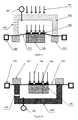
- the present embodiment provides a welding method for substrate and membrane of membrane mobile polymer microfluidic chip, and the schematic diagram for structure welded by using the welding method described in the present embodiment is as indicated in Figure 2 .
- the welding steps are basically as same as those in Embodiment 1, and the only difference is the mode for applying pressure onto membrane (100).
- the air pressure-clamping film mode is adopted to apply pressure onto membrane (100).
- the substrate (100) is fixed, and the surface of substrate (100) is covered with the membrane (200).
- the tensing apparatus (600) is used to tense up the membrane (200), and the surface of substrate (100) is covered with the tensed membrane (200).
- the stratochamber (800) and clamping film (900) are placed on the surface of membrane (200), the stratochamber (800) is sealed up by clamping film (900) in advance, and the stratochamber (800) is equipped with pressure sensor (801) and control valve (802).
- the air is filled into the stratochamber (800) via the control valve (802), and the air pressure forms an air pressure face on the surface of membrane (200), so as to apply pressure onto the membrane (200).
- the air pressure in the stratochamber (800) is adjusted on the basis of the feedback from pressure sensor (801), so as to ensure that the air pressure reaches the desired value.
- the clamping film (900) may be made of the material of which the features are as same as those of membrane (200).
- the deformation of surface of clamping film (900) under a certain welding pressure as the surface of substrate (100) deforms is controlled by applying pressure to clamping film (900) and adjusting the tension of the clamping film (900) and air pressure, so as to control the deformation of membrane (200) in the course of welding, rather than strictly control the tension of membrane (200).
- control valve (802) Since poor air tightness may occur to stratochamber (800), the control valve (802) is opened intermittently on the basis of the feedback from pressure sensor (801) for adjusting the value of air pressure in stratochamber (800), so as to achieve the desired pressure. After the adjustment is completed, the control valve (802) is closed, so as to keep the pressure in stratochamber (800) constant.
- the mask (400) is placed in the light patch of laser (700), as indicated in Figure 2 .
- the mask (400) is be placed on clamping film (900) in advance, and then the clamping film (900) is used to seal up the stratochamber (800); or before the irradiation of laser (700), the mask (400) is be placed on stratochamber (800), and the transparent area on mask (400) is corresponding to the welding area on substrate (100).
- the laser (700) irradiates the welding area on substrate (100) through the transparent area, and the welding area fuses under the action of heat and bonds substrate (100) and membrane (200) together when hardening, so as to complete the welding.
- both the stratochamber (800) and clamping film (900) in the present embodiment are made of transparent materials.
- the air pressure-clamping film mode is adopted to apply pressure, and the air pressure face and clamping film jointly ensure that the membrane (200) is attached to the surface of substrate (100), so that the welding is firm and the weld face is flat and uniform.
- the welding method for substrate and membrane of membrane mobile polymer microfluidic chip in the present embodiment is substantially same as that in Embodiment 2, and the only difference is that no clamping film is adopted to seal up the stratochamber (800), and instead, after the substrate (100) and membrane (200) are properly placed, the membrane (200) is firmly pressed against the stratochamber (800) by using the sealing seat (803) of stratochamber (800), so as to seal up the stratochamber (800).
- the tensing apparatus (600) is used to apply a pulling force to the membrane (200), so as to tense it up.
- the pressure-applying mode is as same as that in Embodiment 2.
- the value of pulling force is adjusted on the basis of the elastic parameters of membrane (200) and the value of air pressure, so as to control the tensile deformation and ensure the welding quality.
- the control valve (802) is opened intermittently for adjusting the air pressure in stratochamber (800) on the basis of the feedback from pressure sensor (801), so as to achieve the desired pressure. After the adjustment is completed, the control valve (802) is closed, so as to keep the pressure in stratochamber (800) constant.
- the mask (400) is placed in the light path of laser (700), as indicated in Figure 3 .
- the mask (400) is be placed on membrane (200) in advance, and then the membrane (200) is used to seal up the stratochamber (800); or before the irradiation of laser (700), the mask (400) is be placed on stratochamber (800), and the transparent area on mask (400) is corresponding to the welding area on substrate (100).
- the laser (700) irradiates the welding area on substrate (100) through the transparent area, and the welding area fuses under the action of heat and bonds substrate (100) and membrane (200) together when hardening, so as to complete the welding.
- the stratochamber (800) is made of transparent material.
- the clamping film (900) is omitted in the present embodiment, so as to reduce the energy loss of laser (700) in light path, improve the accuracy and efficiency of welding, realize the firm welding, and ensure that the weld face is flat and uniform.
- the present embodiment provides a welding method for substrate and membrane of membrane mobile polymer microfluidic chip, as indicated in Figure 4 .
- the present embodiment adopts a different pressure-applying mode, whereby the stratochamber (800) and substrate (100) are on the same side, and the pressure is applied through air extraction. It is detailed as follows:
- the value of pulling force is adjusted on the basis of the elastic parameters of membrane (200) and the value of air pressure, so as to control the tensile deformation and ensure the welding quality.
- the control valve (802) is opened intermittently for adjusting the air pressure in stratochamber (800) on the basis of the feedback from pressure sensor (801), so as to achieve the desired pressure. After the adjustment is completed, the control valve (802) is closed, so as to keep the pressure in stratochamber (800) constant.
- the mask (400) is placed in the light path of the laser (700), as indicated in Figure 4 .
- the mask (400) is placed on membrane (200) and the transparent area on mask (400) is corresponding to the welding area on substrate (100).
- the laser (700) irradiates the welding area on substrate (100) through the transparent area, the welding area fuses under the action of heat and bonds substrate (100) and membrane (200) together when hardening, so as to complete the welding.
- the mask (400) in the light path in the present embodiment As compared with the Embodiments 2 and 3, there is only the mask (400) in the light path in the present embodiment, which enables the light path to achieve the high-precision welding, reduces the energy loss in light path, simplifies the structure, realizes the firm welding and ensures the flat and uniform weld face.
- the present embodiment provides a welding method for substrate and membrane of membrane mobile polymer microfluidic chip, the welding process is substantially same as that in the Embodiments 2, 3 and 4, and the difference is that a pressure-applying mode based on two stratochamber is adopted, as indicated in Figure 5 .
- the first stratochamber (800a) and membrane (200) are on the same side, the second stratochamber (800b) and substrate (100) on the same side. It is detailed as follows:
- the air pressure in first stratochamber (800a) is adjusted on the basis of the feedback from pressure sensor (801a), and at the same time the air pressure in second stratochamber (800b) is adjusted on the basis of the feedback from pressure sensor (801b), so as to ensure that the total air pressure reaches the desired value.
- the clamping film (900) may be made of the material of which the features are as same as those of membrane (200).
- the deformation of surface of clamping film (900) under a certain welding pressure as the surface of substrate (100) deforms is controlled by applying pressure to clamping film (900) and adjusting its tension and air pressure, so as to control the deformation of membrane (200) in the course of welding, rather than strictly control the tension of membrane (200).
- the control valve (802) is opened intermittently on the basis of the feedback from pressure sensor (801a) for adjusting the air pressure in first stratochamber (800a), and at the same time the control valve (802) is opened intermittently on the basis of the feedback from pressure sensor (801b) for adjusting the air pressure in second stratochamber (800b), so as to achieve the desired pressure.
- the control valve (802) and control valve (802b) are closed, so as to keep the pressure in first stratochamber (800a) and second stratochamber (800b) constant.
- the mask 400 is placed in the light path of laser (700), as indicated in Figure 5 .
- the mask (400) is placed on clamping film (900) in advance, and then the first stratochamber (800a) is sealed up by the clamping film (900); or before the irradiation of laser (700), the mask (400) is placed on first stratochamber (800a) and the transparent area on mask (400) is corresponding to the welding area on substrate (100).
- the laser (700) irradiates the welding area on substrate (100) through the transparent area, the welding area fuses under the action of heat and bonds substrate (100) and membrane (200) together when hardening, so as to complete the welding.
- both the first stratochamber (800a) and clamping film (900) in the present embodiment are made of transparent materials.
- the air pressure-clamping film mode is adopted to apply pressure, and the air pressure face and clamping film jointly ensure that the membrane (200) is attached to the surface of substrate (100), so that the welding is firm and the weld face is flat and uniform.
- Two stratochambers apply the pressure at the same time, so that the relatively high pressure can be obtained.
- the present embodiment provides a welding method for substrate and membrane of membrane mobile polymer microfluidic chip.
- the clamping film (900) is omitted, and the first stratochamber (800a) is also sealed up by the membrane (200). It is detailed as follows:
- the air pressure in first stratochamber (800a) is adjusted on the basis of the feedback from pressure sensor (801a), and at the same time the air pressure in second stratochamber (800b) is also adjusted on the basis of the feedback from pressure sensor (801b), so as to ensure that the total air pressure reaches the desired value.
- the value of pulling force is adjusted on the basis of the elastic parameters of membrane (200) and the value of air pressure, so as to control the tensile deformation and ensure the welding quality.
- the control valve (802) is opened intermittently on the basis of the feedback from pressure sensor (801a) for adjusting the air pressure in first stratochamber (800a), and at the same time the control valve (802) is opened intermittently on the basis of the feedback from pressure sensor (801b) for adjusting the air pressure in second stratochamber (800b), so as to achieve the desired pressure.
- the control valve (802) and control valve (802b) are closed, so as to keep the pressure in first stratochamber (800a) and second stratochamber (800b) constant.
- the mask (400) is placed in the light path of laser (700), as indicated in Figure 6 .
- the mask (400) is placed on membrane (200) in advance, or before the irradiation of laser (700), the mask (400) is placed on first stratochamber (800a) and the transparent area on mask (400) is corresponding to the welding area on substrate (100).
- the laser (700) irradiates the welding area on substrate (100) through the transparent area, and the welding area fuses under the action of heat and bonds substrate (100) and membrane (200) together when hardening, so as to complete the welding.
- the first stratochamber (800) in the present embodiment is made of transparent material.
- the clamping film is omitted, so as to reduce the energy loss of laser (700) in light path, improve the accuracy and efficiency of welding, realize the firm welding, and ensure that the weld face is flat and uniform.
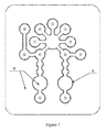
- the whole perimeter is the weld face of membrane
- the non-transparent area of mask is corresponding to the non-welding area B
- the transparent area of mask is corresponding to the welding area A.
- the welding area varies according to the functions of membrane mobile polymer microfluidic chip.
- the welding is carried out after the membrane is tensed up under the action of pressure, so as to ensure that the substrate and membrane of membrane mobile polymer microfluidic chip are welded firmly, the membrane is not damaged and the weld face is flat and uniform; as driven by the air pressure, the welded moving parts and valves can normally operate for more than 5,000 times.
- Table 1 “Date Sheet of Fatigue Testing for Laser-welded Membrane”.
- the pulling force may be adjusted on the basis of the elastic parameters of membrane and the pressure of pressure-applying apparatus, so as to make the membrane flat, control the tensile deformation and ensure the quality of welding.
- the clamping film may be selected on the basis of the membrane parameters and the deformation of weld face under pressure may be controlled by adjust the pulling force of clamping film and the pressure in stratochamber, so as to control weld quality.
- the structure of stratochamber is relatively independent and easy to control.
Landscapes
- Engineering & Computer Science (AREA)
- Mechanical Engineering (AREA)
- Physics & Mathematics (AREA)
- Health & Medical Sciences (AREA)
- Optics & Photonics (AREA)
- Electromagnetism (AREA)
- Chemical & Material Sciences (AREA)
- Toxicology (AREA)
- Fluid Mechanics (AREA)
- General Health & Medical Sciences (AREA)
- Dispersion Chemistry (AREA)
- Analytical Chemistry (AREA)
- Hematology (AREA)
- Clinical Laboratory Science (AREA)
- Chemical Kinetics & Catalysis (AREA)
- Microelectronics & Electronic Packaging (AREA)
- Lining Or Joining Of Plastics Or The Like (AREA)
- Laser Beam Processing (AREA)
Applications Claiming Priority (2)
| Application Number | Priority Date | Filing Date | Title |
|---|---|---|---|
| CN201110235234.0A CN102319956B (zh) | 2011-08-16 | 2011-08-16 | 膜动聚合物微流控芯片的基板与隔膜焊接方法 |
| PCT/CN2012/071781 WO2013023449A1 (zh) | 2011-08-16 | 2012-02-29 | 膜动聚合物微流控芯片的基板与隔膜焊接方法 |
Publications (3)
| Publication Number | Publication Date |
|---|---|
| EP2745977A1 true EP2745977A1 (de) | 2014-06-25 |
| EP2745977A4 EP2745977A4 (de) | 2016-03-09 |
| EP2745977B1 EP2745977B1 (de) | 2018-11-21 |
Family
ID=45447858
Family Applications (1)
| Application Number | Title | Priority Date | Filing Date |
|---|---|---|---|
| EP12823344.2A Active EP2745977B1 (de) | 2011-08-16 | 2012-02-29 | Schweissverfahren für ein substrat mit einer membran und membran aus einem mikrofluidischen polymerchip |
Country Status (5)
| Country | Link |
|---|---|
| US (1) | US9427735B2 (de) |
| EP (1) | EP2745977B1 (de) |
| JP (1) | JP5966006B2 (de) |
| CN (1) | CN102319956B (de) |
| WO (1) | WO2013023449A1 (de) |
Cited By (2)
| Publication number | Priority date | Publication date | Assignee | Title |
|---|---|---|---|---|
| GB2533386A (en) * | 2014-12-18 | 2016-06-22 | Smiths Detection-Watford Ltd | Apparatus and method |
| DE102018210706A1 (de) * | 2018-06-29 | 2020-01-02 | Robert Bosch Gmbh | Adaptive Maske für ein Verfahren zum Laserdurchstrahlschweißen |
Families Citing this family (12)
| Publication number | Priority date | Publication date | Assignee | Title |
|---|---|---|---|---|
| DE102013207683A1 (de) | 2013-04-26 | 2014-11-13 | Robert Bosch Gmbh | Verfahren und Vorrichtung zum Herstellen einer mikrofluidischen Analysekartusche |
| KR101392426B1 (ko) * | 2013-07-08 | 2014-05-07 | 한국기계연구원 | 마이크로 채널 소자 및 마이크로 채널 소자의 제작방법 |
| US9440424B2 (en) * | 2014-05-05 | 2016-09-13 | Picosys Inc | Methods to form and to dismantle hermetically sealed chambers |
| US10838116B2 (en) | 2016-01-06 | 2020-11-17 | University Of Utah Research Foundation | Low-power large aperture adaptive lenses for smart eyeglasses |
| EP3649387A1 (de) * | 2017-07-07 | 2020-05-13 | University of Utah Research Foundation | Durch spannungsänderung angetriebener mikrofluidischer niederspannungsaktuator |
| CN110039911A (zh) * | 2019-05-22 | 2019-07-23 | 宁波禾森自动化设备有限公司 | 一种喷码系统 |
| CN112454914A (zh) * | 2020-10-26 | 2021-03-09 | 广东华焯激光科技有限公司 | 一种微流控芯片焊接方法 |
| CN114433263B (zh) * | 2022-02-08 | 2023-09-01 | 广东永诺医疗科技有限公司 | 一种移液、微滴生成及封膜系统 |
| KR102695706B1 (ko) * | 2022-05-24 | 2024-08-16 | 레이저쎌 주식회사 | 진공챔버를 구비한 가압 방식의 레이저 리플로우 장치 |
| CN116197534A (zh) * | 2023-05-06 | 2023-06-02 | 赫比(成都)精密塑胶制品有限公司 | 激光焊接方法及激光焊接加工工艺 |
| DE102024003596A1 (de) | 2024-10-24 | 2026-04-30 | Hochschule Mittweida (FH), Körperschaft des öffentlichen Rechts | Einrichtung zur Hersteilung wenigstens einer Sensorhülle aus zwei Kunststofffolien |
| CN119771523B (zh) * | 2024-12-18 | 2025-12-19 | 中国科学院微电子研究所 | 一种固定夹持类器官小球的微流控芯片及其制备方法 |
Family Cites Families (18)
| Publication number | Priority date | Publication date | Assignee | Title |
|---|---|---|---|---|
| US5094709A (en) * | 1986-09-26 | 1992-03-10 | General Electric Company | Apparatus for packaging integrated circuit chips employing a polymer film overlay layer |
| EP0290501B1 (de) * | 1986-09-26 | 1993-03-10 | General Electric Company | Verfahren und apparat zum packen integrierter schaltungschips mit einer polymerfilm-bedeckungsschicht |
| US4953287A (en) * | 1987-07-01 | 1990-09-04 | Hewlett-Packard Company | Thermal-bonding process and apparatus |
| US5972780A (en) * | 1996-08-22 | 1999-10-26 | Nippon Telegraph Telephone Corporation | Thin film forming apparatus and method |
| JP3683669B2 (ja) * | 1997-03-21 | 2005-08-17 | 株式会社リコー | 半導体発光素子 |
| ES2149637T3 (es) | 1999-01-28 | 2000-11-01 | Leister Process Tech | Procedimiento de ensamblaje por laser y dispositivo para unir distintas piezas de plastico o plastico con otros materiales. |
| US20100236705A1 (en) * | 2000-07-18 | 2010-09-23 | Chou Stephen Y | Fluidic and Microdevice Apparatus and Methods For Bonding Components Thereof |
| US6486433B2 (en) * | 2001-01-11 | 2002-11-26 | Branson Ultrasonics Corporation | Transparent pressure bladder |
| JP2003001455A (ja) * | 2001-06-15 | 2003-01-08 | Matsushita Electric Ind Co Ltd | 金属と樹脂との接合方法及び装置、制振鋼板の製造方法 |
| ATE271458T1 (de) * | 2002-10-02 | 2004-08-15 | Leister Process Tech | Verfahren und vorrichtung zum bearbeiten von werkstücken mittels eines laserstrahls |
| US7220245B2 (en) * | 2004-05-26 | 2007-05-22 | Kriesel Marshall S | Infusion apparatus |
| US20070125489A1 (en) * | 2005-09-08 | 2007-06-07 | Oregon State University | Microfluidic welded devices or components thereof and method for their manufacture |
| AU2007209758B2 (en) * | 2006-01-24 | 2013-03-28 | Mycrolab Diagnostics Pty Ltd | Methods for low cost manufacturing of complex layered materials and devices |
| JP4514722B2 (ja) * | 2006-02-20 | 2010-07-28 | 富士通セミコンダクター株式会社 | フィルム貼り付け方法、フィルム貼り付け装置および半導体装置の製造方法 |
| JP4948033B2 (ja) * | 2006-05-16 | 2012-06-06 | ローム株式会社 | マイクロ流体回路の製造方法およびその方法により製造したマイクロ流体回路 |
| JP4864074B2 (ja) * | 2008-12-11 | 2012-01-25 | 日東電工株式会社 | 通気構造および通気構造の製造方法 |
| DE102009037404C5 (de) * | 2009-08-13 | 2019-01-10 | Multivac Sepp Haggenmüller Se & Co. Kg | Lasersiegeln von Verpackungen |
| JP5608376B2 (ja) * | 2010-01-14 | 2014-10-15 | 日東電工株式会社 | シート接合体作製方法 |
-
2011
- 2011-08-16 CN CN201110235234.0A patent/CN102319956B/zh active Active
-
2012
- 2012-02-29 EP EP12823344.2A patent/EP2745977B1/de active Active
- 2012-02-29 US US14/238,848 patent/US9427735B2/en active Active
- 2012-02-29 JP JP2014525286A patent/JP5966006B2/ja active Active
- 2012-02-29 WO PCT/CN2012/071781 patent/WO2013023449A1/zh not_active Ceased
Cited By (4)
| Publication number | Priority date | Publication date | Assignee | Title |
|---|---|---|---|---|
| GB2533386A (en) * | 2014-12-18 | 2016-06-22 | Smiths Detection-Watford Ltd | Apparatus and method |
| GB2533386B (en) * | 2014-12-18 | 2019-09-11 | Smiths Detection Watford Ltd | A detection apparatus with pneumatic interface |
| US10695760B2 (en) | 2014-12-18 | 2020-06-30 | Smiths Detection-Watford Limited | Apparatus and method |
| DE102018210706A1 (de) * | 2018-06-29 | 2020-01-02 | Robert Bosch Gmbh | Adaptive Maske für ein Verfahren zum Laserdurchstrahlschweißen |
Also Published As
| Publication number | Publication date |
|---|---|
| CN102319956A (zh) | 2012-01-18 |
| EP2745977B1 (de) | 2018-11-21 |
| US20140216647A1 (en) | 2014-08-07 |
| JP2014528837A (ja) | 2014-10-30 |
| EP2745977A4 (de) | 2016-03-09 |
| JP5966006B2 (ja) | 2016-08-10 |
| US9427735B2 (en) | 2016-08-30 |
| WO2013023449A1 (zh) | 2013-02-21 |
| CN102319956B (zh) | 2015-04-22 |
Similar Documents
| Publication | Publication Date | Title |
|---|---|---|
| US9427735B2 (en) | Welding method for substrate and membrane of membrane mobile polymer microfluidic chip | |
| JP3662156B2 (ja) | 液晶パネル製造装置 | |
| US7282665B2 (en) | Method and apparatus for processing articles with a laser beam | |
| JP7608400B2 (ja) | 仮接合装置 | |
| JP6211074B2 (ja) | プレス装置、真空枠及びプレス成形方法 | |
| TWI538812B (zh) | Panel attachment method and panel attachment | |
| JP2013109836A (ja) | 有機elパネルの製造方法及び有機elパネルの封止装置 | |
| KR102807340B1 (ko) | 전사 장치 및 전사 방법 | |
| JP2012245646A (ja) | 熱圧着装置及び熱圧着方法 | |
| CN113594391A (zh) | 一种贴片装置及硅基oled玻璃盖板的贴合方法 | |
| CN111468821A (zh) | 一种热熔胶带激光加热装置及方法 | |
| JP5451432B2 (ja) | ワーク貼合装置 | |
| CN202199934U (zh) | 膜动聚合物微流控芯片的基板与隔膜焊接装置 | |
| JP7504494B2 (ja) | 真空チャンバーを設けた加圧方式のレーザリフロー装置 | |
| KR20200046558A (ko) | 유리판 접합장치 | |
| CN112103372B (zh) | 柔性板压式太阳电池组件层压机及层压方法 | |
| CN100363824C (zh) | 框胶固化装置和方法以及液晶面板制造方法 | |
| JPH0996822A (ja) | 基板接合装置 | |
| JP3112221B2 (ja) | 液晶セルのギャップ出し方法 | |
| JPH09160056A5 (de) | ||
| JP2004034626A (ja) | 真空貼付け機 | |
| JP3733202B2 (ja) | 液晶表示装置の製造方法及び製造装置 | |
| KR20230062931A (ko) | 레이저 본딩 시스템 및 그 제어방법 | |
| TWI684298B (zh) | 染料敏化電池之電極對位熱壓合方法 | |
| JP3150023B2 (ja) | 液晶セルのギャップ出し装置 |
Legal Events
| Date | Code | Title | Description |
|---|---|---|---|
| PUAI | Public reference made under article 153(3) epc to a published international application that has entered the european phase |
Free format text: ORIGINAL CODE: 0009012 |
|
| 17P | Request for examination filed |
Effective date: 20140314 |
|
| AK | Designated contracting states |
Kind code of ref document: A1 Designated state(s): AL AT BE BG CH CY CZ DE DK EE ES FI FR GB GR HR HU IE IS IT LI LT LU LV MC MK MT NL NO PL PT RO RS SE SI SK SM TR |
|
| DAX | Request for extension of the european patent (deleted) | ||
| RA4 | Supplementary search report drawn up and despatched (corrected) |
Effective date: 20160204 |
|
| RIC1 | Information provided on ipc code assigned before grant |
Ipc: B23K 26/20 20140101AFI20160209BHEP Ipc: B29C 65/16 20060101ALI20160209BHEP |
|
| STAA | Information on the status of an ep patent application or granted ep patent |
Free format text: STATUS: EXAMINATION IS IN PROGRESS |
|
| 17Q | First examination report despatched |
Effective date: 20171011 |
|
| GRAP | Despatch of communication of intention to grant a patent |
Free format text: ORIGINAL CODE: EPIDOSNIGR1 |
|
| STAA | Information on the status of an ep patent application or granted ep patent |
Free format text: STATUS: GRANT OF PATENT IS INTENDED |
|
| INTG | Intention to grant announced |
Effective date: 20180621 |
|
| GRAS | Grant fee paid |
Free format text: ORIGINAL CODE: EPIDOSNIGR3 |
|
| GRAA | (expected) grant |
Free format text: ORIGINAL CODE: 0009210 |
|
| STAA | Information on the status of an ep patent application or granted ep patent |
Free format text: STATUS: THE PATENT HAS BEEN GRANTED |
|
| AK | Designated contracting states |
Kind code of ref document: B1 Designated state(s): AL AT BE BG CH CY CZ DE DK EE ES FI FR GB GR HR HU IE IS IT LI LT LU LV MC MK MT NL NO PL PT RO RS SE SI SK SM TR |
|
| REG | Reference to a national code |
Ref country code: CH Ref legal event code: EP |
|
| REG | Reference to a national code |
Ref country code: IE Ref legal event code: FG4D |
|
| REG | Reference to a national code |
Ref country code: DE Ref legal event code: R096 Ref document number: 602012053878 Country of ref document: DE |
|
| REG | Reference to a national code |
Ref country code: AT Ref legal event code: REF Ref document number: 1066989 Country of ref document: AT Kind code of ref document: T Effective date: 20181215 |
|
| REG | Reference to a national code |
Ref country code: NL Ref legal event code: MP Effective date: 20181121 |
|
| REG | Reference to a national code |
Ref country code: AT Ref legal event code: MK05 Ref document number: 1066989 Country of ref document: AT Kind code of ref document: T Effective date: 20181121 |
|
| PG25 | Lapsed in a contracting state [announced via postgrant information from national office to epo] |
Ref country code: LV Free format text: LAPSE BECAUSE OF FAILURE TO SUBMIT A TRANSLATION OF THE DESCRIPTION OR TO PAY THE FEE WITHIN THE PRESCRIBED TIME-LIMIT Effective date: 20181121 Ref country code: ES Free format text: LAPSE BECAUSE OF FAILURE TO SUBMIT A TRANSLATION OF THE DESCRIPTION OR TO PAY THE FEE WITHIN THE PRESCRIBED TIME-LIMIT Effective date: 20181121 Ref country code: LT Free format text: LAPSE BECAUSE OF FAILURE TO SUBMIT A TRANSLATION OF THE DESCRIPTION OR TO PAY THE FEE WITHIN THE PRESCRIBED TIME-LIMIT Effective date: 20181121 Ref country code: BG Free format text: LAPSE BECAUSE OF FAILURE TO SUBMIT A TRANSLATION OF THE DESCRIPTION OR TO PAY THE FEE WITHIN THE PRESCRIBED TIME-LIMIT Effective date: 20190221 Ref country code: HR Free format text: LAPSE BECAUSE OF FAILURE TO SUBMIT A TRANSLATION OF THE DESCRIPTION OR TO PAY THE FEE WITHIN THE PRESCRIBED TIME-LIMIT Effective date: 20181121 Ref country code: IS Free format text: LAPSE BECAUSE OF FAILURE TO SUBMIT A TRANSLATION OF THE DESCRIPTION OR TO PAY THE FEE WITHIN THE PRESCRIBED TIME-LIMIT Effective date: 20190321 Ref country code: FI Free format text: LAPSE BECAUSE OF FAILURE TO SUBMIT A TRANSLATION OF THE DESCRIPTION OR TO PAY THE FEE WITHIN THE PRESCRIBED TIME-LIMIT Effective date: 20181121 Ref country code: NO Free format text: LAPSE BECAUSE OF FAILURE TO SUBMIT A TRANSLATION OF THE DESCRIPTION OR TO PAY THE FEE WITHIN THE PRESCRIBED TIME-LIMIT Effective date: 20190221 Ref country code: AT Free format text: LAPSE BECAUSE OF FAILURE TO SUBMIT A TRANSLATION OF THE DESCRIPTION OR TO PAY THE FEE WITHIN THE PRESCRIBED TIME-LIMIT Effective date: 20181121 |
|
| PG25 | Lapsed in a contracting state [announced via postgrant information from national office to epo] |
Ref country code: GR Free format text: LAPSE BECAUSE OF FAILURE TO SUBMIT A TRANSLATION OF THE DESCRIPTION OR TO PAY THE FEE WITHIN THE PRESCRIBED TIME-LIMIT Effective date: 20190222 Ref country code: RS Free format text: LAPSE BECAUSE OF FAILURE TO SUBMIT A TRANSLATION OF THE DESCRIPTION OR TO PAY THE FEE WITHIN THE PRESCRIBED TIME-LIMIT Effective date: 20181121 Ref country code: NL Free format text: LAPSE BECAUSE OF FAILURE TO SUBMIT A TRANSLATION OF THE DESCRIPTION OR TO PAY THE FEE WITHIN THE PRESCRIBED TIME-LIMIT Effective date: 20181121 Ref country code: PT Free format text: LAPSE BECAUSE OF FAILURE TO SUBMIT A TRANSLATION OF THE DESCRIPTION OR TO PAY THE FEE WITHIN THE PRESCRIBED TIME-LIMIT Effective date: 20190321 Ref country code: AL Free format text: LAPSE BECAUSE OF FAILURE TO SUBMIT A TRANSLATION OF THE DESCRIPTION OR TO PAY THE FEE WITHIN THE PRESCRIBED TIME-LIMIT Effective date: 20181121 Ref country code: SE Free format text: LAPSE BECAUSE OF FAILURE TO SUBMIT A TRANSLATION OF THE DESCRIPTION OR TO PAY THE FEE WITHIN THE PRESCRIBED TIME-LIMIT Effective date: 20181121 |
|
| PG25 | Lapsed in a contracting state [announced via postgrant information from national office to epo] |
Ref country code: DK Free format text: LAPSE BECAUSE OF FAILURE TO SUBMIT A TRANSLATION OF THE DESCRIPTION OR TO PAY THE FEE WITHIN THE PRESCRIBED TIME-LIMIT Effective date: 20181121 Ref country code: IT Free format text: LAPSE BECAUSE OF FAILURE TO SUBMIT A TRANSLATION OF THE DESCRIPTION OR TO PAY THE FEE WITHIN THE PRESCRIBED TIME-LIMIT Effective date: 20181121 Ref country code: CZ Free format text: LAPSE BECAUSE OF FAILURE TO SUBMIT A TRANSLATION OF THE DESCRIPTION OR TO PAY THE FEE WITHIN THE PRESCRIBED TIME-LIMIT Effective date: 20181121 Ref country code: PL Free format text: LAPSE BECAUSE OF FAILURE TO SUBMIT A TRANSLATION OF THE DESCRIPTION OR TO PAY THE FEE WITHIN THE PRESCRIBED TIME-LIMIT Effective date: 20181121 |
|
| REG | Reference to a national code |
Ref country code: DE Ref legal event code: R097 Ref document number: 602012053878 Country of ref document: DE |
|
| PG25 | Lapsed in a contracting state [announced via postgrant information from national office to epo] |
Ref country code: SK Free format text: LAPSE BECAUSE OF FAILURE TO SUBMIT A TRANSLATION OF THE DESCRIPTION OR TO PAY THE FEE WITHIN THE PRESCRIBED TIME-LIMIT Effective date: 20181121 Ref country code: SM Free format text: LAPSE BECAUSE OF FAILURE TO SUBMIT A TRANSLATION OF THE DESCRIPTION OR TO PAY THE FEE WITHIN THE PRESCRIBED TIME-LIMIT Effective date: 20181121 Ref country code: EE Free format text: LAPSE BECAUSE OF FAILURE TO SUBMIT A TRANSLATION OF THE DESCRIPTION OR TO PAY THE FEE WITHIN THE PRESCRIBED TIME-LIMIT Effective date: 20181121 Ref country code: RO Free format text: LAPSE BECAUSE OF FAILURE TO SUBMIT A TRANSLATION OF THE DESCRIPTION OR TO PAY THE FEE WITHIN THE PRESCRIBED TIME-LIMIT Effective date: 20181121 |
|
| PLBE | No opposition filed within time limit |
Free format text: ORIGINAL CODE: 0009261 |
|
| STAA | Information on the status of an ep patent application or granted ep patent |
Free format text: STATUS: NO OPPOSITION FILED WITHIN TIME LIMIT |
|
| REG | Reference to a national code |
Ref country code: CH Ref legal event code: PL |
|
| 26N | No opposition filed |
Effective date: 20190822 |
|
| PG25 | Lapsed in a contracting state [announced via postgrant information from national office to epo] |
Ref country code: MC Free format text: LAPSE BECAUSE OF FAILURE TO SUBMIT A TRANSLATION OF THE DESCRIPTION OR TO PAY THE FEE WITHIN THE PRESCRIBED TIME-LIMIT Effective date: 20181121 Ref country code: LU Free format text: LAPSE BECAUSE OF NON-PAYMENT OF DUE FEES Effective date: 20190228 Ref country code: SI Free format text: LAPSE BECAUSE OF FAILURE TO SUBMIT A TRANSLATION OF THE DESCRIPTION OR TO PAY THE FEE WITHIN THE PRESCRIBED TIME-LIMIT Effective date: 20181121 |
|
| REG | Reference to a national code |
Ref country code: BE Ref legal event code: MM Effective date: 20190228 |
|
| REG | Reference to a national code |
Ref country code: IE Ref legal event code: MM4A |
|
| PG25 | Lapsed in a contracting state [announced via postgrant information from national office to epo] |
Ref country code: LI Free format text: LAPSE BECAUSE OF NON-PAYMENT OF DUE FEES Effective date: 20190228 Ref country code: CH Free format text: LAPSE BECAUSE OF NON-PAYMENT OF DUE FEES Effective date: 20190228 |
|
| PG25 | Lapsed in a contracting state [announced via postgrant information from national office to epo] |
Ref country code: IE Free format text: LAPSE BECAUSE OF NON-PAYMENT OF DUE FEES Effective date: 20190228 |
|
| PG25 | Lapsed in a contracting state [announced via postgrant information from national office to epo] |
Ref country code: BE Free format text: LAPSE BECAUSE OF NON-PAYMENT OF DUE FEES Effective date: 20190228 |
|
| PG25 | Lapsed in a contracting state [announced via postgrant information from national office to epo] |
Ref country code: TR Free format text: LAPSE BECAUSE OF FAILURE TO SUBMIT A TRANSLATION OF THE DESCRIPTION OR TO PAY THE FEE WITHIN THE PRESCRIBED TIME-LIMIT Effective date: 20181121 |
|
| PG25 | Lapsed in a contracting state [announced via postgrant information from national office to epo] |
Ref country code: MT Free format text: LAPSE BECAUSE OF NON-PAYMENT OF DUE FEES Effective date: 20190228 |
|
| PG25 | Lapsed in a contracting state [announced via postgrant information from national office to epo] |
Ref country code: CY Free format text: LAPSE BECAUSE OF FAILURE TO SUBMIT A TRANSLATION OF THE DESCRIPTION OR TO PAY THE FEE WITHIN THE PRESCRIBED TIME-LIMIT Effective date: 20181121 |
|
| PG25 | Lapsed in a contracting state [announced via postgrant information from national office to epo] |
Ref country code: HU Free format text: LAPSE BECAUSE OF FAILURE TO SUBMIT A TRANSLATION OF THE DESCRIPTION OR TO PAY THE FEE WITHIN THE PRESCRIBED TIME-LIMIT; INVALID AB INITIO Effective date: 20120229 |
|
| PG25 | Lapsed in a contracting state [announced via postgrant information from national office to epo] |
Ref country code: MK Free format text: LAPSE BECAUSE OF FAILURE TO SUBMIT A TRANSLATION OF THE DESCRIPTION OR TO PAY THE FEE WITHIN THE PRESCRIBED TIME-LIMIT Effective date: 20181121 |
|
| PGFP | Annual fee paid to national office [announced via postgrant information from national office to epo] |
Ref country code: GB Payment date: 20260224 Year of fee payment: 15 |
|
| PGFP | Annual fee paid to national office [announced via postgrant information from national office to epo] |
Ref country code: DE Payment date: 20260223 Year of fee payment: 15 |
|
| PGFP | Annual fee paid to national office [announced via postgrant information from national office to epo] |
Ref country code: FR Payment date: 20260224 Year of fee payment: 15 |