EP2745992A2 - Ensemble d'outils pour une machine-outil manuelle - Google Patents
Ensemble d'outils pour une machine-outil manuelle Download PDFInfo
- Publication number
- EP2745992A2 EP2745992A2 EP20130182913 EP13182913A EP2745992A2 EP 2745992 A2 EP2745992 A2 EP 2745992A2 EP 20130182913 EP20130182913 EP 20130182913 EP 13182913 A EP13182913 A EP 13182913A EP 2745992 A2 EP2745992 A2 EP 2745992A2
- Authority
- EP
- European Patent Office
- Prior art keywords
- locking
- tool
- attachment
- tool attachment
- locking body
- Prior art date
- Legal status (The legal status is an assumption and is not a legal conclusion. Google has not performed a legal analysis and makes no representation as to the accuracy of the status listed.)
- Granted
Links
Images





Classifications
-
- B—PERFORMING OPERATIONS; TRANSPORTING
- B23—MACHINE TOOLS; METAL-WORKING NOT OTHERWISE PROVIDED FOR
- B23B—TURNING; BORING
- B23B31/00—Chucks; Expansion mandrels; Adaptations thereof for remote control
- B23B31/02—Chucks
- B23B31/10—Chucks characterised by the retaining or gripping devices or their immediate operating means
- B23B31/12—Chucks with simultaneously-acting jaws, whether or not also individually adjustable
- B23B31/1207—Chucks with simultaneously-acting jaws, whether or not also individually adjustable moving obliquely to the axis of the chuck in a plane containing this axis
- B23B31/123—Chucks with simultaneously-acting jaws, whether or not also individually adjustable moving obliquely to the axis of the chuck in a plane containing this axis with locking arrangements
-
- B—PERFORMING OPERATIONS; TRANSPORTING
- B25—HAND TOOLS; PORTABLE POWER-DRIVEN TOOLS; MANIPULATORS
- B25F—COMBINATION OR MULTI-PURPOSE TOOLS NOT OTHERWISE PROVIDED FOR; DETAILS OR COMPONENTS OF PORTABLE POWER-DRIVEN TOOLS NOT PARTICULARLY RELATED TO THE OPERATIONS PERFORMED AND NOT OTHERWISE PROVIDED FOR
- B25F3/00—Associations of tools for different working operations with one portable power-drive means; Adapters therefor
-
- B—PERFORMING OPERATIONS; TRANSPORTING
- B23—MACHINE TOOLS; METAL-WORKING NOT OTHERWISE PROVIDED FOR
- B23B—TURNING; BORING
- B23B2240/00—Details of connections of tools or workpieces
- B23B2240/04—Bayonet connections
-
- B—PERFORMING OPERATIONS; TRANSPORTING
- B23—MACHINE TOOLS; METAL-WORKING NOT OTHERWISE PROVIDED FOR
- B23B—TURNING; BORING
- B23B31/00—Chucks; Expansion mandrels; Adaptations thereof for remote control
- B23B31/02—Chucks
- B23B31/10—Chucks characterised by the retaining or gripping devices or their immediate operating means
- B23B31/12—Chucks with simultaneously-acting jaws, whether or not also individually adjustable
-
- Y—GENERAL TAGGING OF NEW TECHNOLOGICAL DEVELOPMENTS; GENERAL TAGGING OF CROSS-SECTIONAL TECHNOLOGIES SPANNING OVER SEVERAL SECTIONS OF THE IPC; TECHNICAL SUBJECTS COVERED BY FORMER USPC CROSS-REFERENCE ART COLLECTIONS [XRACs] AND DIGESTS
- Y10—TECHNICAL SUBJECTS COVERED BY FORMER USPC
- Y10T—TECHNICAL SUBJECTS COVERED BY FORMER US CLASSIFICATION
- Y10T279/00—Chucks or sockets
- Y10T279/17—Socket type
- Y10T279/17615—Obliquely guided reciprocating jaws
-
- Y—GENERAL TAGGING OF NEW TECHNOLOGICAL DEVELOPMENTS; GENERAL TAGGING OF CROSS-SECTIONAL TECHNOLOGIES SPANNING OVER SEVERAL SECTIONS OF THE IPC; TECHNICAL SUBJECTS COVERED BY FORMER USPC CROSS-REFERENCE ART COLLECTIONS [XRACs] AND DIGESTS
- Y10—TECHNICAL SUBJECTS COVERED BY FORMER USPC
- Y10T—TECHNICAL SUBJECTS COVERED BY FORMER US CLASSIFICATION
- Y10T279/00—Chucks or sockets
- Y10T279/32—Means to prevent jaw loosening
-
- Y—GENERAL TAGGING OF NEW TECHNOLOGICAL DEVELOPMENTS; GENERAL TAGGING OF CROSS-SECTIONAL TECHNOLOGIES SPANNING OVER SEVERAL SECTIONS OF THE IPC; TECHNICAL SUBJECTS COVERED BY FORMER USPC CROSS-REFERENCE ART COLLECTIONS [XRACs] AND DIGESTS
- Y10—TECHNICAL SUBJECTS COVERED BY FORMER USPC
- Y10T—TECHNICAL SUBJECTS COVERED BY FORMER US CLASSIFICATION
- Y10T408/00—Cutting by use of rotating axially moving tool
- Y10T408/94—Tool-support
- Y10T408/95—Tool-support with tool-retaining means
Definitions
- the present invention relates to a tool attachment for attachment to a mounting interface of a hand tool, with a locking unit which allows in a unlocking position of the tool attachment to the mounting interface of the power tool and in a locked state allows locking of the tool attachment to the mounting interface of the power tool for operation, wherein the locking unit has a rotatable locking body, which is arranged in the unlocking state in a first rotational position and in the locking state in a second rotational position on the mounting interface of the power tool.
- such a tool attachment which has a locking unit for attachment to a mounting interface of a power tool.
- This locking unit is used to lock the tool attachment to the hand tool in an associated locking state to allow operation of the tool attachment to the power tool by transmitting a drive torque from the power tool to the tool attachment.
- a disadvantage of the prior art is that such a bayonet connection can be solved automatically due to vibrations occurring during operation of the power tool. This can damage the tool attachment and / or lead the hand tool and injury to a user of the power tool.
- An object of the invention is therefore to provide a new tool attachment for attachment to a mounting interface of a power tool, in which after a lock on the mounting interface of the power tool automatic release thereof can be prevented.
- a tool attachment for attachment to a mounting interface of a hand tool with a locking unit that allows in an unlocking position of the tool attachment to the mounting interface of the power tool and in a locked state allows locking of the tool attachment to the mounting interface of the power tool for operation.
- the locking unit has a rotatable locking body, wherein the unlocking state is associated with a first rotational position of the locking body and the locking state, a second rotational position of the locking body.
- the locking unit has a locking member which is designed to prevent in the locking state, a rotation of the locking body from the second rotational position to the first rotational position.
- the invention thus makes it possible to provide a tool attachment, in which an automatic release of the locking body of the tool attachment from the mounting interface of the power tool by the locking member can be reliably and reliably prevented during operation of an associated hand tool on which the tool attachment is locked in the locked state.
- the locking member is adapted to cooperate in the locked state with a locking element associated with the attachment interface of the power tool.
- the blocking element preferably has at least one locking toothing.
- the locking member is at least partially resilient and has at least one locking portion which is acted upon in the locked state by an elastic deformation of the locking member against the mounting interface of the power tool.
- the invention thus enables the provision of a reliable and cost-effective locking member.
- the locking portion is adapted to lock in the locking state in the locking teeth to prevent the rotation of the locking body from the second rotational position to the first rotational position.
- the locking unit has an actuating element which is designed to allow a rotation of the locking body from the first to the second rotational position.
- the invention thus makes it possible to provide a tool attachment whose locking unit is designed for simple and user-friendly handling.
- the locking body is preferably at least partially tubular and the actuating element is rotatably mounted on the outer circumference of the locking body.
- At least one driver element and the locking body at least one driving element are formed on the actuating element, wherein the driver element and the driving member are adapted to cooperate upon actuation of the actuating element for rotating the locking body from the first to the second rotational position for rotational driving of the locking body.
- the invention thus enables the provision of a tool attachment, in which a safe and reliable rotational drive of the locking body can be ensured by the actuator.
- the driving member is adapted to allow a rotational movement of the actuating element relative to the locking body at least by a predetermined angle of rotation.
- the actuating element is preferably designed to act on the locking member in the locking state at least partially against the mounting interface of the power tool.
- the actuating element has a control cam, which is designed to enable, in the locking state, the at least partially loading of the locking member against the fastening interface of the handheld power tool.
- the actuating element is associated with a blocking member which is adapted to block the actuating element in the locking state in a blocking position on the locking body, in which the actuating element acts on the locking member at least in sections against the mounting interface of the power tool.
- the invention thus makes it possible to provide a tool attachment in which the actuating element can be locked reliably and reliably on the locking body when the blocking member is acted on.
- the blocking member is preferably at least partially resilient and has a blocking portion which is detachably fixable in the blocking position in a provided on the locking body fixing member.
- the fixing member is formed in the manner of a recess and the blocking portion is adapted to lock in the blocking position in the fixing member to prevent in the locked state, an automatic rotation of the actuating element relative to the locking body.
- the locking member and the blocking member are preferably integrally formed.
- the locking body on locking elements which are designed in the manner of bayonets to form a bayonet connection with the mounting interface of the power tool.
- the invention thus makes it possible to provide a tool attachment which can be reliably and reliably connected to the attachment interface of the handheld power tool via a robust and stable bayonet connection.
- a handheld power tool having a fastening interface for fastening a tool attachment, which has a locking body which can be locked on the fastening interface.
- the attachment interface is associated with a blocking element which is designed to block a rotationally secured locking of the locking body of the tool attachment to the attachment interface.
- a tool system with a handheld power tool, which has a fastening interface, and with a tool attachment for fastening to the fastening interface of the handheld power tool.
- the tool attachment has a locking unit which, in an unlocking state, makes it possible to place the tool attachment on the attachment interface of the handheld power tool and, in a locking state, makes it possible to lock the tool attachment to the attachment interface of the handheld power tool for operation.
- the locking unit has a rotatable locking body, which is arranged in the unlocking state in a first rotational position and in the locking state in a second rotational position on the mounting interface of the power tool.
- the locking unit has a locking member which is designed to prevent in the locking state, a rotation of the locking body from the second rotational position to the first rotational position.
- a handheld power tool having a fastening interface for the rotationally secured fastening of a tool attachment, wherein the fastening interface is fastened to a transmission housing of the handheld power tool.
- the invention thus makes it possible to provide a handheld power tool with a compact and robust construction.
- the power tool on a tool holder for receiving an insert tool, which has a spring-loaded locking sleeve for locking the insert tool, wherein the locking sleeve is at least partially inserted into the mounting interface.
- the attachment interface is adapted to allow an aligned in a predetermined angular position attachment of the tool attachment to the transmission housing.
- an at least partially cone-shaped centering for axial centering of the tool attachment is provided at the attachment interface.
- the attachment interface is preferably associated with a blocking element which is designed to block a rotationally secured locking of a locking body, lockable on the attachment interface, of the tool attachment to the attachment interface.
- an automatic release of the locking body of the tool attachment can be reliably and reliably prevented by the attachment interface of the power tool in their operation by the locking member.
- Fig. 1 shows a provided with a tool holder 140 hand tool 100, which has a housing 110 with a handle 126, and an enlarged section of the power tool 100.
- the power tool 100 is connected to the mains independent power supply mechanically and electrically connected to a battery pack 130.
- the hand tool 100 is exemplified as a cordless rotary impact wrench. It should be understood, however, that the present invention is not limited to cordless impact drivers, but rather may be applied to a variety of hand tool machines having a tool holder corresponding to the tool holder 140, regardless of whether the hand tool is electrically, i. network-independent with the battery pack 130 or network-dependent, and / or non-electrically operable.
- one of the battery pack 130 powered, electric drive motor 114, a gear 118 and an optional hammer mechanism 122 are arranged in the housing 110.
- the drive motor 114 can be actuated, for example via a manual switch 128, that is to say switched on and off, and preferably electronically controllable or controllable in such a way that both a reversing operation and specifications with respect to a desired rotational speed can be realized.
- the drive motor 114 is an electronically commutated drive motor, preferably a DC motor, illustratively having stator and rotor components 111 and 117, respectively.
- the stator components 111 exemplarily form an external stator and the rotor components 117 exemplify an internal rotor.
- the description of a drive motor constructed in the manner of an electronically commutated drive motor with external stator and internal rotor is merely exemplary in nature and should not be taken as limiting the invention, which also applies to a drive motor with an inner stator and outer rotor or e.g. can be used in a brush-type commutator motor.
- the drive motor 114 is connected to the transmission 118 via an associated motor shaft 116, which permits rotation of the motor shaft 116 into rotation of a drive member 120 provided between the transmission 118 and percussion gear 122, e.g. a drive shaft, converted. This conversion is preferably such that the drive member 120 rotates relative to the motor shaft 116 with increased torque but reduced rotational speed.
- the drive motor 114 is illustratively arranged in a motor housing 115 and the gear 118 in a gear housing 119, wherein the gear housing 119 and the motor housing 115 are arranged in the housing 110 by way of example.
- the optional percussion mechanism 122 connected to the drive member 120 is exemplified by a rotary impact mechanism which generates high-intensity abrupt rotation pulses and transmits them to an output shaft 124, eg an output spindle.
- An exemplary impact mechanism, with which the impact mechanism 122 can be realized, is in the DE 20 2006 014 850 U1 which is hereby incorporated by reference and whose teachings are to be understood as a part of the present description, so that a detailed description of the percussion mechanism 122 can be omitted here for the sake of brevity of the description.
- the tool holder 140 On the output shaft 124, the tool holder 140 is formed, which illustratively has a receiving body 147 with polygonal socket 148, which is provided for receiving insert tools with external polygonal couplings.
- a receiving body 147 with polygonal socket 148 On the outer circumference of z. B. rotatably and / or integrally connected to the output shaft 124 receiving body 147 is an example of a spring element in a direction away from the power tool 100 axial direction 199 spring-loaded locking sleeve 149 arranged to lock suitable inserts in the polygonal socket 148.
- the tool holder 140 is exemplified in the manner of a bit holder, i. for receiving a trained in the manner of a screwdriver bits insert tool 170, which is inserted in the direction of the power tool 100, as indicated by an arrow 198, in the polygon socket 148.
- a screwdriver bit e.g. is of the so-called HEX type
- HEX HEX
- the present invention is not limited to use of HEX wrench bits, but also other insert tools depending on a particular configuration of the tool receptacle 140, e.g.
- the handheld power tool 100 is associated with a mounting interface 150, which is illustratively axially and radially fixed immovably in the area of the bit holder 140 on the housing 110 and is hereinafter referred to as the "machine interface 150" for clarity of description. It should be noted, however, that the machine interface 150 is merely exemplified as a separate component and, alternatively, may be integrally formed with the housing 110.
- the machine interface 150 serves for the rotationally secured attachment of an associated tool attachment (200 in FIG Fig. 2 ), which may be formed, for example, in the manner of a chuck, angle or Exzentervorsatzes.
- the machine interface 150 has a fastening element 151 secured against rotation on an end face 112 of the housing 110.
- This is exemplified at least partially sleeve or annular and in the region of a ring on the end 112 on the housing 110 arranged end closure or protective sleeve 158 with suitable fasteners, such as screws or rivets attached, but may alternatively also integral with the housing 110 be formed.
- the fastening element 151 preferably encloses the bit holder 140, at least in sections, with a predetermined radial spacing, in order to allow an axial displacement of the locking sleeve 149 of the bit holder 140 in the interior of the fastening element 151.
- the fastening element 151 has on its outer circumference at least one blocking element 155 and at least two retaining elements 152, 154.
- the blocking element 155 preferably has at least one locking toothing 156, and the at least two retaining elements 152, 154 are designed, for example, in the manner of bayonets for forming a bayonet connection.
- bayonet connection is merely exemplary in nature and is not intended to limit the invention.
- alternative mounting options for the machine interface 150 can be used in which a corresponding tool attachment (200 in Fig. 2 ) can be fastened via a rotational movement on the machine interface 150, for example a so-called wire-bar lock, etc.
- At least sectionally cone-shaped centering aid 153 for the axial centering of a locking unit (202 in FIG Fig. 2 ) of an associated tool attachment (200 in Fig. 2 ), wherein the fastening element 151 is adapted to the axial centering of the associated tool attachment (200 in Fig. 2 ) on the housing 110.
- an exemplary annular, at least partially funnel-shaped centering surface 159 for forming the centering aid 153 is provided on the inner circumference of the fastening element 151.
- the centering surface 159 is designed to be funnel-shaped only by way of example and not as a limitation of the invention. Rather, a conical configuration on an additional centering ring can be realized. Accordingly, a reference to the term "cone-shaped" in the context of the present invention represents both a reference to a conical and a funnel-shaped configuration of a corresponding component.
- the centering 153 may instead of a single ring and funnel-shaped centering surface 159 have a plurality of cone-shaped arc sections, etc.
- the fastening element 151 has at least one and, by way of example, three optional angle setting members 157. These serve e.g. in an attachment of a trained in the manner of an angle or Exzentervorsatzes tool attachment on the machine interface 150 for specifying a predetermined angular position.
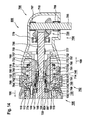
- Fig. 2 1 shows an exemplary tool attachment 200 attached to the machine interface 150 of the hand tool 100 of FIG Fig. 1 is secured against rotation fastened.
- the tool attachment 200 is designed according to an embodiment in the manner of a drill chuck attachment and has, for example, a locking unit 202 and a chuck unit 204. It should be noted, however, that the tool attachment 200 is designed by way of example only as a drill chuck attachment and not to limit the invention. Rather, the tool attachment 200 may have any configuration, for example in the manner of an angle attachment, a Exzentervorsatzes etc.
- the chuck unit 204 has by way of example a support body 294 on which a plurality of clamping jaws 290 are mounted, which are provided with a clamping body 292 provided with a clamping sleeve 280 for clamping an associated insertion tool, e.g. a round drill, is actuated.
- the support body 294 is e.g. secured against rotation by a screw connection 275 to a first axial end portion 274 of the locking unit 202 associated actuator 270, so that the support body 294 rotates with a rotational movement of the actuator 270 with this.
- the support body 294 may be e.g. be connected via a press connection with the actuator 270 or be integrally formed therewith.
- a drive shaft 268 is received in a rotationally secured manner, e.g. via a press connection 266, so that the actuator 270 rotates with a rotational movement of the drive shaft 268 with this.
- the drive shaft 268 and the actuator 270 may also be integrally formed.
- a polygonal driving contour 265 is formed at a free axial end of the drive shaft 268, which is taken up by way of example in a second axial end region of the actuating member 270.
- An outer periphery of the second axial end portion of the actuator 270 is rotatably movable in one of the lock unit 202 associated bearing member 212, for example, a rolling bearing designed in the manner of a radial bearing, or preferably pressed into this, so that the chuck unit 204 is rotatably mounted on the locking unit 202.
- the bearing element 212 is axially fixed in position in the axial direction of the actuating member 270 between an annular shoulder 226 formed thereon and a securing ring 227 fastened thereto.
- a suitable realization of the chuck unit 204 is sufficiently known from the prior art, so that a detailed description of the chuck unit 204 can be dispensed with here for the sake of brevity of the description.
- the locking unit 202 is according to one embodiment, at least for rotationally secured attachment to the machine interface 150 of the power tool 100 of Fig. 1 and, in an unlocked state, allows the tool attachment 200 to be placed on the machine interface 150 and, in a locked state, to lock the tool attachment 200 to the machine interface 150 for operation.
- the locking unit 202 preferably has a rotatable locking body 300, which in the unlocking state in a first rotational position and in the locking state in a second rotational position on the machine interface 150 of the power tool 100 of Fig. 1 is arranged as below Fig. 10 and 11 described.
- This locking body 300 preferably has on its inner circumference at least two holding members 298, 299, for example in the manner of bayonets to form a bayonet connection with the bayonets 152, 154 of the machine interface 150 of Fig. 1 are formed.
- the locking body 300 is at least partially tubular and forms an inner space 216, and an outer periphery 245, on which an outer collar 215 is provided.
- the outer collar 215 is located at an axial end (399 in FIG. 3) facing away from the chuck unit 204 Fig. 3 ) of the locking body 300 is formed at its opposite axial end (398 in FIG Fig. 3 )
- An inner annular groove 297 is provided, wherein in the annular groove 297, an inner retaining ring 228 is attached.
- the locking body 300 illustratively has an inner annular shoulder 223, wherein in the region between the annular shoulder 223 and the retaining ring 228, for example, a centering member 260 is axially fixed in position.
- an elastic element 240 is preferably arranged, for example, an O-ring made of rubber material, a plate spring, a wave washer, a cylindrical compression spring, etc.
- the bearing element 212 is arranged and preferred pressed.
- an outer grip surface 249 preferably sleeve-shaped actuating element 600 and rotatably mounted, which has an inner projection 241 which is illustratively annular.
- the actuating element 600 is designed to allow a rotation of the locking body 300 from the first to the second rotational position.
- an at least partially resilient locking member 400 and a blocking member 500 are arranged according to an embodiment.
- the locking member 400 is at least partially fixed in position on the locking body 300 and the blocking member 500 on the actuating element 600.
- the locking member 400 is adapted to prevent locking of the locking body 300 from its second rotational position to its first rotational position in the locking state of the locking unit 202, wherein the locking member 400 preferably with the machine interface 150 of the power tool 100 of Fig. 1 associated blocking element 155 of Fig. 1 interacts.
- the actuating element 600 is preferably designed to act on the locking member 400 in the locking state of the locking unit 202 at least partially against the machine interface 150 of the power tool 100, as below Fig. 11 described.
- the blocking member 500 is configured according to an embodiment to block the actuating element 600 in the locking state of the locking unit 202 in a blocking position on the locking body 300, in which the actuating element 600 at least partially against the locking interface 400 against the machine interface 150 of the power tool 100 of Fig. 1 acted upon to prevent an automatic rotation of the actuating element 600 relative to the locking body 300.
- the locking member 400 and the blocking member 500 as described above are merely exemplary in nature and not serve to limit the invention. Rather, the locking member and the blocking member can also be integrally formed and, for example, together held on the locking body, as exemplified below Fig. 12 described.
- the described, tubular or sleeve-shaped embodiments of the locking body 300 and the actuating element 600 also have only exemplary character and are not to be understood as limiting the invention. Rather, the locking body 300 and the actuator may be formed, for example, each of two or more arcuate elements, etc.
- the centering member 260 and the machine interface 150 of the hand tool 100 of Fig. 1 preferably form complementary geometric shapes that provide axial centering of the locking unit 202 on the machine interface 150 of FIG Fig. 1 allow and preferably mesh with each other. These complementary geometric shapes are designed to form a positive connection in the axial direction of the locking unit 202. Therefore, in the context of the present invention, complementary geometric shapes are to be understood more generally as geometric shapes that can be joined together to form a positive connection.
- the centering member 260 of the locking unit 202 has at least one at least sectionally cone-shaped centering aid 220. This is for engaging in the at the machine interface 150 of the power tool 100 of Fig. 1 provided, at least partially funnel-shaped centering 153 provided and preferably at least partially in the manner of a ring 221 formed with an at least partially beveled outer periphery 225 at an axial end portion 262 of the locking unit 202.
- the centering aid 220 instead of the ring 221, for example, have a plurality of cone-shaped arc sections, etc.
- Tool attachment 200 For mounting the tool attachment 200 on the machine interface 150 of the power tool 100 of Fig. 1 Tool attachment 200 is moved in the direction 198 of FIG Fig. 1 brought to the machine interface 150 and positioned so that the actuator 270 to rest against the locking sleeve 149 of the tool holder 140 of the power tool 100 is brought, so that the free end of the drive shaft 268 engages at least partially in the empty inner polygon socket 148 of the tool holder 140.
- the tool attachment 200 is displaced in the direction 198 toward the machine interface 150, wherein the actuator 270 also displaces the locking sleeve 149 in the direction 198 and thus unlocks the tool holder 140 so that the free end of the drive shaft 268 is inserted into the polygonal socket 148 ,
- the tool attachment 200 is pushed onto the machine interface 150 such that the locking body 300 against the fastening element 151 of the machine interface 150 of Fig. 1 is present or surrounds this, so that by actuation of the actuating element 600, the locking unit 202 on the machine interface 150 of Fig. 1 can be locked.
- the at least partially cone-shaped centering aid 220 of the locking unit 202 against the at least partially funnel-shaped centering aid 153 of the machine interface 150 of Fig. 1 brought into contact.
- this is after unlocking the locking unit 202 in the direction of 199 of Fig. 1 from the machine interface 150 of Fig. 1 away.
- centering aids 220 and 153 of FIG Fig. 1 merely illustrative cone-shaped and not to limit the invention. Rather, they need only as described above to form a positive connection suitable, complementary geometric shapes. Accordingly, for example, the centering aid 153 of the machine interface 150 as in Fig. 1 be funnel-shaped, while the centering aid 220 of the tool attachment 200, for example, is cylindrical or annular. Alternatively, for example, the centering aid 220 of the tool attachment 200 as described above conical, ie conical or funnel-shaped, be formed while the centering aid 153 of the machine interface 150 of Fig. 1 is cylindrical or annular, etc.
- Fig. 3 shows the tubular locking body 300 of Fig. 2 having at its axial periphery 399 at its outer periphery 245 the outer collar 215 and at its inner circumference the bayonet-type retaining member 298. At its opposite axial end 398, the inner annular groove 297 and the inner annular shoulder 223 are formed. Furthermore, at the axial end 398, for example, three recesses 340 are assigned for receiving Holding members of the centering member 260 of Fig. 2 formed, for example, are directed radially outwardly from the centering member 260 in the manner of projections.
- At least one driving element 330 is formed on the locking body 300, illustratively on its outer circumference 245. This is exemplified web-like and aligned, starting from the outer collar 215, for example, parallel to the axis of rotation of the locking body 300 in the direction of the axial end 398 aligned, as with the arrow 199 of Fig. 2 indicated.
- a fixing member 320 is illustratively formed on the outer collar 215.
- a passage opening 310 is formed in the region of the outer collar 215.
- Fig. 4 shows the approximately 180 ° rotated about its axis of rotation locking body 300 of Fig. 3 , In this one is contrary to Fig. 3 by the rotation of the axial end 399 bayonet-like holding member 299 visible.
- the locking member 400 of Fig. 2 attached to the outer periphery 245 of the locking body 300.
- the locking member 400 has a fixing portion 410, which is fixed by way of example in a groove-like recess 415 of the outer collar 215 of the locking body 300.
- the locking member 400 is illustratively U-shaped with a at least partially parallel to the outer collar 215 extending Sperrfederarm 417 and a running parallel to this support arm 419 provided.
- the Sperrfederarm 417 engages with its free end through the passage opening 310 of the locking body 300.
- the support arm 419 is preferably completely against the outer periphery 245 of the locking body 300.
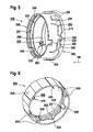
- Fig. 5 shows the in the direction of the arrow 199 of 3 and 4 mirrored locking body 300 of Fig. 4 to illustrate the passage through the opening 310 by sweeping the free end of the Sperrfederarms 417 of the locking member 400 of Fig. 4 that forms a barrier portion 420 according to one embodiment.
- Fig. 5 shows Fig. 5 the illustratively arranged on the outer circumference 245 of the locking body 300 blocking member 500 of Fig. 2 like at Fig. 2 described and in Fig. 6 shown on the actuator 600 of Fig. 2 is fixed and exemplified having the shape of a brace.
- the blocking member 500 is preferably at least partially resilient and has a blocking portion 520 which is releasably fixed to the provided on the outer collar 215 of the locking body 300 fixing member 320.
- the fixing member 320 has at least one locking groove designed in the manner of a recess, into which the blocking portion 520 formed in the manner of a resilient latching nose can be latched.
- Fig. 6 shows the sleeve-shaped actuator 600 of Fig. 2 with the arranged on the inner circumference locking member 400 of Fig. 4 and 5 to illustrate the mounting portion 410 of Fig. 4 and the locking portion 420 of FIG Fig. 5
- the actuating element 600 may have on its outer circumference 249 an at least partially rubberized gripping surface, which allows a comfortable and safe operation of the actuating element 600.
- At least one driver element 630 is formed on the inner circumference of the actuating element 600.
- This is exemplified web-like and aligned, starting from the inner projection 241, for example, parallel to the axis of rotation of the actuating element 600 in the direction of the projection 241 facing away from the axial end of the actuating element 600 aligned, ie in Fig. 2 In the direction of the arrow 198.
- a fastening member 620 for fixing the blocking member 500 of Fig. 2 and 5 arranged in the region of the inner projection 241.
- This illustratively has two recesses in which the free ends of the blocking member 500 designed in the manner of a brace are arranged.
- the free ends can be permanently attached in any way permanently in the two recesses.
- Fig. 7 shows the tilted about its axis of rotation actuator 600 of Fig. 6 with the arranged on the inner circumference locking member 400 of Fig. 4 and a control cam 650 formed on the inner circumference according to an embodiment for actuating the locking member 400 or its locking spring arm 417.
- This is preferably designed to be in the locking state of the locking unit 202 of Fig. 2 an at least partially loading of the locking member 400 against the machine interface 150 of the power tool 100 of Fig. 1 to enable.
- Fig. 8 shows the about 160 ° rotated about its axis of rotation actuator 600 of Fig. 6 without the locking member 400 of Fig. 4 and 5 to illustrate the cam 650 of Fig. 7 ,
- a release portion 652 in which the Sperrfederarm 417 of the locking member 400 can spring radially outward in a release position, and a illustratively formed in the manner of a radially inwardly directed projection engaging portion 656, with the Sperrfederarm 417 in a locked position radially inwardly can be applied.
- a tapered transition portion 654 is preferably formed, via which the Sperrfederarm 417 can be transferred from its release to its locked position, and vice versa.
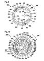
- Fig. 9 shows an assembly 900 with the locking body 300 of Fig. 3 to 5 and the rotationally movable on the outer circumference 245 mounted actuator 600 of Fig. 6 to 8 , As well as the interposed blocking and blocking members 400 and 500 of 4 to 6 ,
- the locking body 300 and the actuating element 600 are exemplary in the unlocking state of the locking unit 202 of Fig. 2 shown in which the blocking portion 520 of the blocking member 500 is locked in a first recess 922 of the fixing member 320 in an unlocked position and the Sperrfederarm 417 of the locking member 400 in its release position radially outwardly against the release portion 652 of the control cam 650 springs.
- the locking body 300 can be rotated by rotation of the actuating element 600 in the direction of an arrow 999 - in FIG Fig. 9 clockwise - be twisted to the locking unit 202 of Fig. 2 from the unlocking to the locked state.
- the driving members 330 of the locking body 300 are preferably designed to allow a rotational movement of the actuating element 600 relative to the locking body 300 at least by a predetermined angle of rotation 910 to allow a transfer of the blocking member 500 from the unlocking to the blocking position, in which its blocking portion 520 snaps into a second recess 924 of the fixing member 320, and to allow a transfer of the locking member 400 from its release to its locked position.
- the driver elements 630 After such a relative rotation about the angle of rotation 910, the driver elements 630, viewed in the direction of the arrow 999, bear against the driving elements 330. For example, is a driver element 932 after the relative rotation about the rotation angle 910 against a driving member 934 on.
- the driver elements 630 of the actuating element 600 and the entraining members 330 of the locking body 300 which now abut against one another in the direction of the arrow 999, are preferably designed to rotate the locking body 300 from its axis first cooperate in its second rotational position for rotational drive of the locking body 300.
- Fig. 10 shows a tool system 1000 with the hand tool 100 of Fig. 1 and the tool attachment 200 of Fig. 2 of which, to simplify the drawing, only the machine interface 150 of Fig. 1 and the assembly 900 of FIG Fig. 9 are shown.
- the assembly 900 is arranged for releasable attachment or locking of the tool attachment 200 on the machine interface 150 such that the bayonets 298, 299 and 152, 154 of the locking body 300 and the machine interface 150 by a rotation of the actuator 600 in the direction 999 of Fig. 9 , and thus the locking body 300 from its shown first rotational position to its in Fig. 11 shown second rotational position, can be locked against each other.
- the bayonets 298, 299 and 152, 154 are first brought into engagement with each other such that by the elastic member 240 of Fig. 2 a clamping force between the bayonets 298 and 152 or 299 and 154 is constructed, which is greater than the spring forces of between the recesses 922 and 924 to be transferred blocking portion 520 of the blocking member 500 and along the tapered transition portion 654 of the cam 650 leading to Sperrfederarms 417th of the locking member 400.
- a clamping force between the bayonets 298 and 152 or 299 and 154 is constructed, which is greater than the spring forces of between the recesses 922 and 924 to be transferred blocking portion 520 of the blocking member 500 and along the tapered transition portion 654 of the cam 650 leading to Sperrfederarms 417th of the locking member 400.
- this rattle noise or a clatter is generated, which provides the user with an auditive inference.
- This noise preferably does not occur when releasing the bayonet connection, since here the connection forces are preferably greater than the spring forces described above by the built-up clamping force, so that the engagement of the locking portion 420 is released into the locking teeth 156 before the bayonet connection is released ,
- Fig. 11 shows the tool system 1000 of Fig. 10 in the locking state of the locking unit 202 of Fig. 2 after a rotation of the actuating element 600 in the direction of the arrow 999 and thus of the locking body 300 in its second rotational position.
- Fig. 11 illustrates the arrangement of blocking in the blocking position in the recess 924 of the fixing member 320 arranged blocking portion 520 of the blocking member 500 and acted upon by an elastic deformation against the machine interface 150 of the power tool 100 locking member 400, the locking portion 420 engages the locking teeth 156 to an automatic rotation of the locking body 300 from its second to the first rotational position of FIGS. 9 and 10 to prevent.
- clarified Fig. 11 the radially inwardly acted upon by the loading portion 656 of the cam 650 Sperrfederarm 417th
- Fig. 12 shows a tool system 1200 with the power tool 100 of Fig. 1 , of which only the machine interface 150 is shown to simplify the drawing, and the tool attachment 200 of FIG Fig. 2 comprising a locking body 300 ', an actuating member 600' and a locking and blocking member 400 ', which are formed according to an alternative embodiment.
- functionally identical but structurally possibly slightly modified elements in both embodiments have identical reference numerals.
- the locking and blocking member 400 ' is formed integrally with a locking portion 420' and disposed on the inner circumference of the locking body 300 '.
- Such a one-piece design of the locking and blocking member 400 ' requires some structural changes to the locking body 300' and the operating member 600 'as opposed to the locking body 300 of FIG Fig. 3 to 5 and the actuator 600 of Fig. 5 to 8 ,
- illustrative locking and blocking member 400 ' has only one locking member portion 417' and one blocking member portion 520 ', each having the functionality of locking spring arm 417 and locking portion 520, respectively Fig. 4 and 5 take.
- Fig. 13 11 shows an exemplary tool attachment 700 according to an alternative embodiment, which is also preferably for attachment to the machine interface 150 of the hand tool 100 of FIG Fig. 1 is trained.
- the tool attachment 700 is designed in the manner of an angle attachment and has, by way of example, an attachment interface 702 designated below as “attachment interface” for clarity of the description and a drive unit 704, also referred to below as "angled drive section".
- attachment interface for clarity of the description
- a drive unit 704 also referred to below as "angled drive section”.
- the tool attachment 700 is formed by way of example only as an angle attachment and not to limit the invention. Rather, the tool attachment 700 may have any configuration, for. In the manner of an eccentric attachment, a chuck attachment, etc.
- the tool attachment 700 will be referred to as "the angle attachment 700" hereinafter.
- the angle drive section 704 has an attachment housing 710 in which a drive shaft 798 that can be driven in rotation is rotatably mounted in two bearing elements 777, 779.
- the drive shaft 798 serves to drive a at a predetermined angle, illustratively 90 °, arranged for this output shaft 705, which is also rotatably mounted in the attachment housing 710, for example in two bearing elements 787, 789, and z. B. for receiving the screwdriver bit 170 of Fig. 1 can be trained.
- a suitable implementation of the angle drive section 704 is well known in the art, so here a detailed description of the angle drive section 704 can be dispensed with for brevity of description.
- an at least partially sleeve-shaped or tubular-shaped angle adjustment element 772 is arranged, through which the drive shaft 798 passes.
- This Winkeleinstellelement 772 is preferably rigid, d. H. axially and radially immovably connected to the attachment housing 710 and / or formed integrally therewith.
- an end-side Winkeleinstellveriereung 774 is provided at its other axial end 771.
- the drive shaft 798 is associated with a provided with a free end 788 actuator 797, the functionality of the functionality of the actuator 270 of Fig. 2 corresponds so that here for the sake of conciseness of the description to a detailed description of this is omitted.
- the drive shaft 798 and the actuator 797 may also be integrally formed.
- the actuator 797 is exemplarily disposed inside the Winkeleinstellelements 772 and preferably radially spaced therefrom.
- the drive shaft 798 is rotatable relative to the actuator 797.
- the drive shaft 798 z. B. in a pressed into the actuator 797 sliding bearing, z. B. a sintered bearing to be mounted rotatably.
- the intent interface 702 is used to attach the tool attachment 700 on an associated hand tool, z. B. the power tool 100 of Fig. 1 , and illustratively has an angular position setting unit 770, which is also used in the tool attachment 200 of FIG Fig. 2
- the locking unit 760 is designed to, in a locking state, the tool attachment 700 for operation on the power tool to lock in a predetermined angular position at this and to allow removal of the tool attachment 700 from the power tool in an unlocked state.
- the Winkelpositionseinstellech 770 is adapted to allow adjustment of the predetermined angular position of the tool attachment 700 for operation on the power tool.
- the angular position setting unit 770 is operable in the locking state of the locking unit 760 to allow a change in the predetermined angular position.
- Such an operation for changing the predetermined angular position is preferably carried out by a combined longitudinal and rotational movement of the attachment housing 710.
- the locking unit 760 has a locking body 762, in particular an at least partially tubular-shaped locking body or a locking body provided with a tubular receiving portion 761.
- the Winkeleinstellelement 772 is longitudinally and rotatably mounted in the tubular receiving portion 761 and thus in the locking unit 760.
- the latter passes via an annular shoulder 781 from the tubular receiving section 761, on the one hand, into a widened region 783 and, on the other hand, into a centering link 731, which, for. B. at least two arcuate, in the longitudinal direction of the tool attachment 700, ie in the direction 198 of Fig.
- Beveled centering 776, 778 has. It should be noted, however, that the centering member 731 merely by way of example has the at least two arcuate tapered centering regions 776, 778 and not for the purpose of limiting the invention. Rather, the centering member 731 may also comprise a single centering area formed in the manner of a truncated cone.
- At least two locking elements 766 (and 768 in FIG Fig. 14 ) are provided, which are exemplified in the manner of bayonets to form a bayonet connection.
- an actuating ring 764 is arranged on the outer circumference of this widened region 783 by way of example, which can be actuated to lock the locking body 762 to the handheld power tool, wherein the locking body 762 and the actuating ring 764 can be formed in one piece.
- On the outer circumference of the tubular receiving portion 761 is illustratively a return sleeve 750 axially and radially movably mounted.
- Ring collar 714 which is formed on one of the annular shoulder 781 of the tubular receiving portion 761 facing the axial end of the return sleeve 750, against the annular shoulder 781 from, and engages at its other axial end in a provided on the attachment housing 710 annular groove 717 a.
- the return sleeve 750 may be formed on the attachment housing 710 and / or formed integrally therewith.
- a spring element 780 As a compression spring, provided that the restoring sleeve 750 with a predetermined spring force in the direction of the annular shoulder 781, ie in the direction of 198 of Fig. 1 , pretentious.
- the annular groove 718 is formed by way of example in the region of an axial end 732 of the tubular receiving section 761 facing the angular drive section 704.
- FIG. 12 shows an exemplary tooling system 800 illustratively illustrating the power tool 100 of FIG Fig. 1 and the angle attachment 700 of Fig. 13 to illustrate an exemplary assembly of the angle attachment 700 on the power tool 100.
- the machine interface 150 of Fig. 1 is arranged, and in which the output shaft 124 is rotatably mounted in an illustrative roller bearing 824, wherein on the output shaft 124, the tool holder 140 of Fig. 1 is arranged.
- the machine interface 150 is arranged on the gear housing 119 according to one embodiment.
- the fastener 151 with suitable fasteners, z. As screws or rivets, attached to the gear housing 119.
- the angle attachment 700 For mounting the angle attachment 700 on the machine interface 150 of the power tool 100, the angle attachment 700 in the direction 198 of Fig. 1 to the machine interface 150 of Fig. 1 introduced and positioned in a predetermined angular position so that the extended portion 783 of the tubular receiving portion 761 in the region of the fastening element 151 of the machine interface 150 is arranged.
- the actuator 797 of the angle attachment 700 is brought with its free end 788 to rest against the locking sleeve 149 of the tool holder 140 of the power tool 100, so that the free end 769 of the drive shaft 798 sections engages in the empty inner polygon socket 148 of the tool holder 140 and is prevented from complete intervention by example of the tool holder 140 associated locking balls 749.
- locking balls 749, or other suitable locking elements are from the locking sleeve 149 of the tool holder 140 to a z. B. the skilled person known manner radially inwardly applied, thus preventing unimpeded insertion of the drive shaft 768 in the polygon socket 148, wherein the locking sleeve 149 of a spring element 897 in the direction away from the power tool 100 axial direction 199 of Fig. 1 is spring loaded.
- the angle attachment 700 is now in the direction of the power tool 100, d. H. in the direction 198, pushed onto the machine interface 150, z. B. until the extended portion 783 of the tubular receiving portion 761 abuts against the fastening element 151 of the machine interface 150, so brought by rotation of the actuating ring 764 of the locking unit 760 of the tool attachment 700 whose bayonets 766, 768 into engagement with the bayonets 152, 154 of the fastener 151 and thus can be locked to them so that the locking unit 760 transitions from its unlocked state to the locked state.
- the attachment housing 710 of the angle attachment 700 is acted upon by a predetermined spring force applied by the spring element 780 of the locking unit 760 of the tool attachment 700 in the direction 198 of the handheld power tool 100.
- the locking sleeve 149 of the tool holder 140 is displaced by the actuator 797 of the angle attachment 700 against a spring force applied by the spring element 897 in the direction 198, so that the free end 769 of the drive shaft 798 in the Inner polygon socket 148 can be inserted.
- a one-handed assembly of the tool attachment 700 is made possible on the power tool 100, wherein the drive shaft 798 tangentially and axially play and preferably exclusively for torque transmission in the polygon socket 148 of the receiving body 147 of the tool holder 140 is added.
- the tapered centering portions 776, 778 of the tubular receiving portion 761 of the tool attachment 700 are brought into abutment against the centering aid 153 of the fixing member 151 formed in the manner of an annular cone surface 159.
- the Winkeleinstellveriereung 774 of the Winkeleinstellelements 772 of the tool attachment 700 is brought into engagement with the Winkeleinstellgliedern 157 of the fastener 151.
- the predetermined angular position for operation of the tool attachment 700 is fixed to the power tool 100.
- the actuating ring 764 of the angle attachment 700 and thus the entire angle attachment 700 is released, whereupon the actuator 797 is acted upon by the spring force of the spring element 897 of the locking sleeve 149 of the tool holder 140 in the direction 199, so that an axial displacement of the entire angle attachment 700 in the Direction 199 is enforced.
- the bayonet connection between the bayonets 766, 768 of the tool attachment 700 and the bayonets 152, 154 of the fastener 151 is additionally secured.
Landscapes
- Engineering & Computer Science (AREA)
- Mechanical Engineering (AREA)
- Gripping On Spindles (AREA)
- Percussive Tools And Related Accessories (AREA)
- Automatic Tool Replacement In Machine Tools (AREA)
Applications Claiming Priority (2)
| Application Number | Priority Date | Filing Date | Title |
|---|---|---|---|
| DE102012221320 | 2012-11-22 | ||
| DE201310213804 DE102013213804A1 (de) | 2012-11-22 | 2013-07-15 | Werkzeugvorsatz für eine Handwerkzeugmaschine |
Publications (3)
| Publication Number | Publication Date |
|---|---|
| EP2745992A2 true EP2745992A2 (fr) | 2014-06-25 |
| EP2745992A3 EP2745992A3 (fr) | 2018-05-30 |
| EP2745992B1 EP2745992B1 (fr) | 2020-08-05 |
Family
ID=50625757
Family Applications (1)
| Application Number | Title | Priority Date | Filing Date |
|---|---|---|---|
| EP13182913.7A Active EP2745992B1 (fr) | 2012-11-22 | 2013-09-04 | Ensemble d'outils pour une machine-outil manuelle |
Country Status (4)
| Country | Link |
|---|---|
| US (1) | US9694428B2 (fr) |
| EP (1) | EP2745992B1 (fr) |
| CN (1) | CN103831799B (fr) |
| DE (1) | DE102013213804A1 (fr) |
Cited By (2)
| Publication number | Priority date | Publication date | Assignee | Title |
|---|---|---|---|---|
| WO2016135216A1 (fr) * | 2015-02-25 | 2016-09-01 | Robert Bosch Gmbh | Machine-outil portative |
| DE102019113212A1 (de) * | 2019-05-10 | 2020-11-12 | Festool Gmbh | Vorsatzgerät und Hand-Werkzeugmaschine mit Vorsatzgerät |
Families Citing this family (27)
| Publication number | Priority date | Publication date | Assignee | Title |
|---|---|---|---|---|
| US10512971B2 (en) * | 2013-08-28 | 2019-12-24 | Positec Power Tools (Suzhou) Co., Ltd. | Power tool and operation method for quick locking and releasing working attachment thereof |
| US10131042B2 (en) | 2013-10-21 | 2018-11-20 | Milwaukee Electric Tool Corporation | Adapter for power tool devices |
| CN203665475U (zh) * | 2013-12-19 | 2014-06-25 | 麦太保电动工具(中国)有限公司 | 用于连接电动工具与转角器的连接装置 |
| US9751176B2 (en) * | 2014-05-30 | 2017-09-05 | Black & Decker Inc. | Power tool accessory attachment system |
| DE102015206634A1 (de) * | 2015-04-14 | 2016-10-20 | Robert Bosch Gmbh | Werkzeugvorsatz für eine Handwerkzeugmaschine |
| DE102015206622B4 (de) | 2015-04-14 | 2024-05-23 | Robert Bosch Gmbh | Werkzeugvorsatz für eine Handwerkzeugmaschine |
| DE102015209017B4 (de) | 2015-05-18 | 2025-10-02 | Robert Bosch Gmbh | Zwischenvorsatz für eine Handwerkzeugmaschine |
| DE102016224186A1 (de) * | 2016-12-06 | 2018-06-07 | Robert Bosch Gmbh | Adaptervorsatz zum Einspannen eines Rundschafteinsatzwerkzeugs |
| EP3338958A1 (fr) | 2016-12-23 | 2018-06-27 | HILTI Aktiengesellschaft | Appareil d'outillage |
| EP3338959A1 (fr) * | 2016-12-23 | 2018-06-27 | HILTI Aktiengesellschaft | Appareil d'outillage |
| EP3338956A1 (fr) * | 2016-12-23 | 2018-06-27 | HILTI Aktiengesellschaft | Appareil d'outillage |
| EP3338957A1 (fr) * | 2016-12-23 | 2018-06-27 | HILTI Aktiengesellschaft | Appareil d'outillage |
| DE102017205097B4 (de) | 2017-03-27 | 2025-04-17 | Robert Bosch Gmbh | Zubehörvorrichtung mit Verriegelungseinheit |
| KR102360161B1 (ko) * | 2017-05-29 | 2022-02-09 | 현대자동차주식회사 | 스핀들 장치 및 그의 작동방법 |
| DE102018201090A1 (de) * | 2018-01-24 | 2019-07-25 | Robert Bosch Gmbh | Haltevorrichtung für eine Handwerkzeugmaschine |
| DE102018203522A1 (de) * | 2018-03-08 | 2019-09-12 | Robert Bosch Gmbh | Handwerkzeugmaschine |
| WO2019183311A1 (fr) * | 2018-03-23 | 2019-09-26 | Milwaukee Electric Tool Corporation | Mécanisme de fixation destiné à un outil électrique |
| DE102018118323A1 (de) * | 2018-07-30 | 2020-01-30 | C. & E. Fein Gmbh | Zubehörteil |
| JP7195967B2 (ja) * | 2019-02-18 | 2022-12-26 | 日東工器株式会社 | 動力工具 |
| JP7480173B2 (ja) * | 2019-05-02 | 2024-05-09 | フェスツール ゲーエムベーハー | 手持ち工作機械用アタッチメント装置 |
| DE102019215328A1 (de) * | 2019-10-07 | 2021-04-08 | Robert Bosch Gmbh | Werkzeug, Abtrieb und Werkzeugabtrieb-Wechselsystem zum Wechseln eines Abtriebs eines Werkzeugs |
| US20210331300A1 (en) * | 2020-04-28 | 2021-10-28 | Snap-On Incorporated | Quick change indexable ratchet head |
| CN111590524B (zh) * | 2020-06-11 | 2024-11-05 | 浙江德硕科技股份有限公司 | 多功能动力工具的头身快换结构及多功能动力工具 |
| EP4063075A1 (fr) * | 2021-03-25 | 2022-09-28 | Hilti Aktiengesellschaft | Appareil outil |
| DE102022209284A1 (de) * | 2022-09-07 | 2024-03-07 | Robert Bosch Gesellschaft mit beschränkter Haftung | Handwerkzeugmaschine mit einer Werkzeugaufnahme |
| WO2025117585A1 (fr) | 2023-11-30 | 2025-06-05 | Stanley Black & Decker, Inc. | Outil électrique à têtes multiples et système de fixation associé et systèmes de fixation de têtes sur celui-ci |
| US12594657B2 (en) | 2023-11-30 | 2026-04-07 | Stanley Black & Decker, Inc. | Multi-headed power tool and systems for fastening heads thereon |
Citations (1)
| Publication number | Priority date | Publication date | Assignee | Title |
|---|---|---|---|---|
| DE202006014850U1 (de) | 2006-09-27 | 2006-11-23 | Robert Bosch Gmbh | Mechanisches Schlagwerk |
Family Cites Families (16)
| Publication number | Priority date | Publication date | Assignee | Title |
|---|---|---|---|---|
| US3545776A (en) * | 1968-06-18 | 1970-12-08 | Jacobs Mfg Co | Combined chuck spindle and chuck locking collar |
| US3724237A (en) * | 1971-06-07 | 1973-04-03 | Black & Decker Mfg Co | Attachment coupling for power tool |
| DE2249234A1 (de) * | 1972-10-07 | 1974-04-18 | Bosch Gmbh Robert | Schnellwechselwerkzeugaufnahme |
| DE3636027A1 (de) * | 1986-10-23 | 1988-04-28 | Hilti Ag | Handgeraet mit loesbarem werkzeughalter |
| DE4108038C2 (de) * | 1991-03-13 | 1994-04-28 | Doerries Scharmann Gmbh | Werkzeugmaschine mit einer in einem Träger gelagerten Antriebsspindel und auswechselbaren, mit dem Träger kuppelbaren Bearbeitungsköpfen |
| DE9203627U1 (de) * | 1992-03-18 | 1993-07-22 | Robert Bosch Gmbh, 70469 Stuttgart | Handwerkzeugmaschine mit Werkzeughalter |
| DE4445858B4 (de) * | 1994-12-22 | 2008-05-08 | Röhm Gmbh | Bohrvorrichtung |
| US6079716A (en) * | 1997-12-12 | 2000-06-27 | Black & Decker Inc. | Removable chuck |
| US6688611B2 (en) * | 1997-12-12 | 2004-02-10 | Black & Decker Inc. | Removable chuck |
| US6551037B2 (en) * | 1997-12-12 | 2003-04-22 | Black & Decker Inc. | Removable chuck |
| CA2370981C (fr) | 2001-02-14 | 2009-12-29 | Black & Decker Inc. | Mandrin amovible |
| DE20317695U1 (de) * | 2003-11-14 | 2004-02-19 | Röhm Gmbh | Bohrvorrichtung |
| CN200942566Y (zh) | 2006-08-28 | 2007-09-05 | 李跃辉 | 一种可调整刀具角度的电镐 |
| DE102007006329A1 (de) * | 2006-12-08 | 2008-06-19 | Robert Bosch Gmbh | Aufsatz für eine Handwerkzeugmaschine |
| DE102006059349A1 (de) | 2006-12-15 | 2008-06-19 | Robert Bosch Gmbh | Elektrohandwerkzeugmaschine mit einem Werkzeugverriegelungssystem |
| DE102007000453A1 (de) | 2007-08-20 | 2009-02-26 | Hilti Aktiengesellschaft | Wechselbare Werkzeugaufnahme |
-
2013
- 2013-07-15 DE DE201310213804 patent/DE102013213804A1/de not_active Withdrawn
- 2013-09-04 EP EP13182913.7A patent/EP2745992B1/fr active Active
- 2013-11-19 US US14/084,338 patent/US9694428B2/en active Active
- 2013-11-21 CN CN201310590588.6A patent/CN103831799B/zh active Active
Patent Citations (1)
| Publication number | Priority date | Publication date | Assignee | Title |
|---|---|---|---|---|
| DE202006014850U1 (de) | 2006-09-27 | 2006-11-23 | Robert Bosch Gmbh | Mechanisches Schlagwerk |
Cited By (6)
| Publication number | Priority date | Publication date | Assignee | Title |
|---|---|---|---|---|
| WO2016135216A1 (fr) * | 2015-02-25 | 2016-09-01 | Robert Bosch Gmbh | Machine-outil portative |
| JP2018505066A (ja) * | 2015-02-25 | 2018-02-22 | ローベルト ボッシュ ゲゼルシャフト ミット ベシュレンクテル ハフツング | 手持ち式工作機械 |
| US10478959B2 (en) | 2015-02-25 | 2019-11-19 | Robert Bosch Gmbh | Hand-held power tool |
| DE102019113212A1 (de) * | 2019-05-10 | 2020-11-12 | Festool Gmbh | Vorsatzgerät und Hand-Werkzeugmaschine mit Vorsatzgerät |
| EP3965996A1 (fr) * | 2019-05-10 | 2022-03-16 | Festool GmbH | Appareil accessoire et machine-outil portative dotée d'un appareil accessoire |
| US12005559B2 (en) | 2019-05-10 | 2024-06-11 | Festool Gmbh | Attachment and portable power tool having an attachment |
Also Published As
| Publication number | Publication date |
|---|---|
| CN103831799A (zh) | 2014-06-04 |
| DE102013213804A1 (de) | 2014-05-22 |
| US9694428B2 (en) | 2017-07-04 |
| US20160008893A9 (en) | 2016-01-14 |
| EP2745992A3 (fr) | 2018-05-30 |
| EP2745992B1 (fr) | 2020-08-05 |
| CN103831799B (zh) | 2017-10-03 |
| US20150115554A1 (en) | 2015-04-30 |
Similar Documents
| Publication | Publication Date | Title |
|---|---|---|
| EP2745992B1 (fr) | Ensemble d'outils pour une machine-outil manuelle | |
| EP2745990B1 (fr) | Ensemble d'outils pour une machine-outil manuelle | |
| EP2745991B1 (fr) | Ensemble d'outils pour une machine-outil manuelle | |
| EP3241653B1 (fr) | Ensemble d'outils et système d'outil | |
| EP2260980B1 (fr) | Élément rapporté pour une machine-outil à main | |
| EP3261805B1 (fr) | Machine-outil portative | |
| EP2580022B1 (fr) | Machine-outil à main munie d'un raccordement d'outil | |
| DE102011084499A1 (de) | Werkzeugvorsatz | |
| EP2745993B1 (fr) | Ensemble d'outils pour une machine-outil manuelle | |
| DE102014207713B4 (de) | Werkzeugvorsatz für eine Handwerkzeugmaschine | |
| DE102011084495A1 (de) | Werkzeugvorsatz | |
| DE102015206622B4 (de) | Werkzeugvorsatz für eine Handwerkzeugmaschine | |
| DE102015204806B4 (de) | Handwerkzeugmaschine | |
| DE102012220905B4 (de) | Handwerkzeugmaschine mit einer Befestigungsschnittstelle | |
| EP2539094B1 (fr) | Machine-outil portative | |
| EP3463728A1 (fr) | Adaptateur pour serrage rapide | |
| DE102012211907A1 (de) | Drehschlagschrauber mit einem Schlagwerk | |
| DE102012220835A1 (de) | Werkzeugvorsatz mit einem Werkzeugwechselmagazin | |
| DE102015200828A1 (de) | Werkzeugvorsatz für eine Handwerkzeugmaschine | |
| DE102013204782A1 (de) | Handwerkzeugmaschine mit einer Werkzeugaufnahme, die eine Mehrkant-Innenaufnahme und eine Mehrkant-Außenaufnahme aufweist | |
| DE202013008724U1 (de) | Werkzeugvorsatz für eine Handwerkzeugmaschine | |
| DE102013204225A1 (de) | Handwerkzeugmaschine mit einer Antriebswelle zum drehenden Antrieb einer Werkzeugaufnahme | |
| DE10109956A1 (de) | Handwerkzeugmaschine | |
| EP3517247B1 (fr) | Dispositif de maintien pour une machine-outil portative | |
| DE102013209173A1 (de) | Handwerkzeugmaschine mit einer Spindellockvorrichtung |
Legal Events
| Date | Code | Title | Description |
|---|---|---|---|
| PUAI | Public reference made under article 153(3) epc to a published international application that has entered the european phase |
Free format text: ORIGINAL CODE: 0009012 |
|
| 17P | Request for examination filed |
Effective date: 20130904 |
|
| AK | Designated contracting states |
Kind code of ref document: A2 Designated state(s): AL AT BE BG CH CY CZ DE DK EE ES FI FR GB GR HR HU IE IS IT LI LT LU LV MC MK MT NL NO PL PT RO RS SE SI SK SM TR |
|
| AX | Request for extension of the european patent |
Extension state: BA ME |
|
| PUAL | Search report despatched |
Free format text: ORIGINAL CODE: 0009013 |
|
| AK | Designated contracting states |
Kind code of ref document: A3 Designated state(s): AL AT BE BG CH CY CZ DE DK EE ES FI FR GB GR HR HU IE IS IT LI LT LU LV MC MK MT NL NO PL PT RO RS SE SI SK SM TR |
|
| AX | Request for extension of the european patent |
Extension state: BA ME |
|
| RIC1 | Information provided on ipc code assigned before grant |
Ipc: B25F 3/00 20060101AFI20180425BHEP |
|
| STAA | Information on the status of an ep patent application or granted ep patent |
Free format text: STATUS: REQUEST FOR EXAMINATION WAS MADE |
|
| R17P | Request for examination filed (corrected) |
Effective date: 20181130 |
|
| RBV | Designated contracting states (corrected) |
Designated state(s): AL AT BE BG CH CY CZ DE DK EE ES FI FR GB GR HR HU IE IS IT LI LT LU LV MC MK MT NL NO PL PT RO RS SE SI SK SM TR |
|
| GRAP | Despatch of communication of intention to grant a patent |
Free format text: ORIGINAL CODE: EPIDOSNIGR1 |
|
| STAA | Information on the status of an ep patent application or granted ep patent |
Free format text: STATUS: GRANT OF PATENT IS INTENDED |
|
| INTG | Intention to grant announced |
Effective date: 20200225 |
|
| RAP1 | Party data changed (applicant data changed or rights of an application transferred) |
Owner name: ROBERT BOSCH GMBH |
|
| GRAS | Grant fee paid |
Free format text: ORIGINAL CODE: EPIDOSNIGR3 |
|
| GRAA | (expected) grant |
Free format text: ORIGINAL CODE: 0009210 |
|
| STAA | Information on the status of an ep patent application or granted ep patent |
Free format text: STATUS: THE PATENT HAS BEEN GRANTED |
|
| AK | Designated contracting states |
Kind code of ref document: B1 Designated state(s): AL AT BE BG CH CY CZ DE DK EE ES FI FR GB GR HR HU IE IS IT LI LT LU LV MC MK MT NL NO PL PT RO RS SE SI SK SM TR |
|
| REG | Reference to a national code |
Ref country code: GB Ref legal event code: FG4D Free format text: NOT ENGLISH |
|
| REG | Reference to a national code |
Ref country code: CH Ref legal event code: EP |
|
| REG | Reference to a national code |
Ref country code: AT Ref legal event code: REF Ref document number: 1298059 Country of ref document: AT Kind code of ref document: T Effective date: 20200815 |
|
| REG | Reference to a national code |
Ref country code: DE Ref legal event code: R096 Ref document number: 502013014980 Country of ref document: DE |
|
| REG | Reference to a national code |
Ref country code: IE Ref legal event code: FG4D Free format text: LANGUAGE OF EP DOCUMENT: GERMAN |
|
| REG | Reference to a national code |
Ref country code: LT Ref legal event code: MG4D |
|
| REG | Reference to a national code |
Ref country code: NL Ref legal event code: MP Effective date: 20200805 |
|
| PG25 | Lapsed in a contracting state [announced via postgrant information from national office to epo] |
Ref country code: PT Free format text: LAPSE BECAUSE OF FAILURE TO SUBMIT A TRANSLATION OF THE DESCRIPTION OR TO PAY THE FEE WITHIN THE PRESCRIBED TIME-LIMIT Effective date: 20201207 Ref country code: NO Free format text: LAPSE BECAUSE OF FAILURE TO SUBMIT A TRANSLATION OF THE DESCRIPTION OR TO PAY THE FEE WITHIN THE PRESCRIBED TIME-LIMIT Effective date: 20201105 Ref country code: ES Free format text: LAPSE BECAUSE OF FAILURE TO SUBMIT A TRANSLATION OF THE DESCRIPTION OR TO PAY THE FEE WITHIN THE PRESCRIBED TIME-LIMIT Effective date: 20200805 Ref country code: GR Free format text: LAPSE BECAUSE OF FAILURE TO SUBMIT A TRANSLATION OF THE DESCRIPTION OR TO PAY THE FEE WITHIN THE PRESCRIBED TIME-LIMIT Effective date: 20201106 Ref country code: SE Free format text: LAPSE BECAUSE OF FAILURE TO SUBMIT A TRANSLATION OF THE DESCRIPTION OR TO PAY THE FEE WITHIN THE PRESCRIBED TIME-LIMIT Effective date: 20200805 Ref country code: HR Free format text: LAPSE BECAUSE OF FAILURE TO SUBMIT A TRANSLATION OF THE DESCRIPTION OR TO PAY THE FEE WITHIN THE PRESCRIBED TIME-LIMIT Effective date: 20200805 Ref country code: LT Free format text: LAPSE BECAUSE OF FAILURE TO SUBMIT A TRANSLATION OF THE DESCRIPTION OR TO PAY THE FEE WITHIN THE PRESCRIBED TIME-LIMIT Effective date: 20200805 Ref country code: FI Free format text: LAPSE BECAUSE OF FAILURE TO SUBMIT A TRANSLATION OF THE DESCRIPTION OR TO PAY THE FEE WITHIN THE PRESCRIBED TIME-LIMIT Effective date: 20200805 Ref country code: BG Free format text: LAPSE BECAUSE OF FAILURE TO SUBMIT A TRANSLATION OF THE DESCRIPTION OR TO PAY THE FEE WITHIN THE PRESCRIBED TIME-LIMIT Effective date: 20201105 |
|
| PG25 | Lapsed in a contracting state [announced via postgrant information from national office to epo] |
Ref country code: NL Free format text: LAPSE BECAUSE OF FAILURE TO SUBMIT A TRANSLATION OF THE DESCRIPTION OR TO PAY THE FEE WITHIN THE PRESCRIBED TIME-LIMIT Effective date: 20200805 Ref country code: RS Free format text: LAPSE BECAUSE OF FAILURE TO SUBMIT A TRANSLATION OF THE DESCRIPTION OR TO PAY THE FEE WITHIN THE PRESCRIBED TIME-LIMIT Effective date: 20200805 Ref country code: PL Free format text: LAPSE BECAUSE OF FAILURE TO SUBMIT A TRANSLATION OF THE DESCRIPTION OR TO PAY THE FEE WITHIN THE PRESCRIBED TIME-LIMIT Effective date: 20200805 Ref country code: LV Free format text: LAPSE BECAUSE OF FAILURE TO SUBMIT A TRANSLATION OF THE DESCRIPTION OR TO PAY THE FEE WITHIN THE PRESCRIBED TIME-LIMIT Effective date: 20200805 Ref country code: IS Free format text: LAPSE BECAUSE OF FAILURE TO SUBMIT A TRANSLATION OF THE DESCRIPTION OR TO PAY THE FEE WITHIN THE PRESCRIBED TIME-LIMIT Effective date: 20201205 |
|
| PG25 | Lapsed in a contracting state [announced via postgrant information from national office to epo] |
Ref country code: DK Free format text: LAPSE BECAUSE OF FAILURE TO SUBMIT A TRANSLATION OF THE DESCRIPTION OR TO PAY THE FEE WITHIN THE PRESCRIBED TIME-LIMIT Effective date: 20200805 Ref country code: CZ Free format text: LAPSE BECAUSE OF FAILURE TO SUBMIT A TRANSLATION OF THE DESCRIPTION OR TO PAY THE FEE WITHIN THE PRESCRIBED TIME-LIMIT Effective date: 20200805 Ref country code: EE Free format text: LAPSE BECAUSE OF FAILURE TO SUBMIT A TRANSLATION OF THE DESCRIPTION OR TO PAY THE FEE WITHIN THE PRESCRIBED TIME-LIMIT Effective date: 20200805 Ref country code: RO Free format text: LAPSE BECAUSE OF FAILURE TO SUBMIT A TRANSLATION OF THE DESCRIPTION OR TO PAY THE FEE WITHIN THE PRESCRIBED TIME-LIMIT Effective date: 20200805 Ref country code: SM Free format text: LAPSE BECAUSE OF FAILURE TO SUBMIT A TRANSLATION OF THE DESCRIPTION OR TO PAY THE FEE WITHIN THE PRESCRIBED TIME-LIMIT Effective date: 20200805 |
|
| REG | Reference to a national code |
Ref country code: CH Ref legal event code: PL |
|
| REG | Reference to a national code |
Ref country code: DE Ref legal event code: R097 Ref document number: 502013014980 Country of ref document: DE |
|
| PG25 | Lapsed in a contracting state [announced via postgrant information from national office to epo] |
Ref country code: AL Free format text: LAPSE BECAUSE OF FAILURE TO SUBMIT A TRANSLATION OF THE DESCRIPTION OR TO PAY THE FEE WITHIN THE PRESCRIBED TIME-LIMIT Effective date: 20200805 Ref country code: MC Free format text: LAPSE BECAUSE OF FAILURE TO SUBMIT A TRANSLATION OF THE DESCRIPTION OR TO PAY THE FEE WITHIN THE PRESCRIBED TIME-LIMIT Effective date: 20200805 |
|
| PLBE | No opposition filed within time limit |
Free format text: ORIGINAL CODE: 0009261 |
|
| STAA | Information on the status of an ep patent application or granted ep patent |
Free format text: STATUS: NO OPPOSITION FILED WITHIN TIME LIMIT |
|
| REG | Reference to a national code |
Ref country code: BE Ref legal event code: MM Effective date: 20200930 |
|
| PG25 | Lapsed in a contracting state [announced via postgrant information from national office to epo] |
Ref country code: LU Free format text: LAPSE BECAUSE OF NON-PAYMENT OF DUE FEES Effective date: 20200904 Ref country code: SK Free format text: LAPSE BECAUSE OF FAILURE TO SUBMIT A TRANSLATION OF THE DESCRIPTION OR TO PAY THE FEE WITHIN THE PRESCRIBED TIME-LIMIT Effective date: 20200805 |
|
| 26N | No opposition filed |
Effective date: 20210507 |
|
| GBPC | Gb: european patent ceased through non-payment of renewal fee |
Effective date: 20201105 |
|
| PG25 | Lapsed in a contracting state [announced via postgrant information from national office to epo] |
Ref country code: IT Free format text: LAPSE BECAUSE OF FAILURE TO SUBMIT A TRANSLATION OF THE DESCRIPTION OR TO PAY THE FEE WITHIN THE PRESCRIBED TIME-LIMIT Effective date: 20200805 |
|
| PG25 | Lapsed in a contracting state [announced via postgrant information from national office to epo] |
Ref country code: SI Free format text: LAPSE BECAUSE OF FAILURE TO SUBMIT A TRANSLATION OF THE DESCRIPTION OR TO PAY THE FEE WITHIN THE PRESCRIBED TIME-LIMIT Effective date: 20200805 Ref country code: LI Free format text: LAPSE BECAUSE OF NON-PAYMENT OF DUE FEES Effective date: 20200930 Ref country code: IE Free format text: LAPSE BECAUSE OF NON-PAYMENT OF DUE FEES Effective date: 20200904 Ref country code: CH Free format text: LAPSE BECAUSE OF NON-PAYMENT OF DUE FEES Effective date: 20200930 Ref country code: BE Free format text: LAPSE BECAUSE OF NON-PAYMENT OF DUE FEES Effective date: 20200930 |
|
| REG | Reference to a national code |
Ref country code: AT Ref legal event code: MM01 Ref document number: 1298059 Country of ref document: AT Kind code of ref document: T Effective date: 20200904 |
|
| PG25 | Lapsed in a contracting state [announced via postgrant information from national office to epo] |
Ref country code: GB Free format text: LAPSE BECAUSE OF NON-PAYMENT OF DUE FEES Effective date: 20201105 |
|
| PG25 | Lapsed in a contracting state [announced via postgrant information from national office to epo] |
Ref country code: AT Free format text: LAPSE BECAUSE OF NON-PAYMENT OF DUE FEES Effective date: 20200904 |
|
| PG25 | Lapsed in a contracting state [announced via postgrant information from national office to epo] |
Ref country code: IS Free format text: LAPSE BECAUSE OF FAILURE TO SUBMIT A TRANSLATION OF THE DESCRIPTION OR TO PAY THE FEE WITHIN THE PRESCRIBED TIME-LIMIT Effective date: 20201205 Ref country code: TR Free format text: LAPSE BECAUSE OF FAILURE TO SUBMIT A TRANSLATION OF THE DESCRIPTION OR TO PAY THE FEE WITHIN THE PRESCRIBED TIME-LIMIT Effective date: 20200805 Ref country code: MT Free format text: LAPSE BECAUSE OF FAILURE TO SUBMIT A TRANSLATION OF THE DESCRIPTION OR TO PAY THE FEE WITHIN THE PRESCRIBED TIME-LIMIT Effective date: 20200805 Ref country code: CY Free format text: LAPSE BECAUSE OF FAILURE TO SUBMIT A TRANSLATION OF THE DESCRIPTION OR TO PAY THE FEE WITHIN THE PRESCRIBED TIME-LIMIT Effective date: 20200805 |
|
| PG25 | Lapsed in a contracting state [announced via postgrant information from national office to epo] |
Ref country code: MK Free format text: LAPSE BECAUSE OF FAILURE TO SUBMIT A TRANSLATION OF THE DESCRIPTION OR TO PAY THE FEE WITHIN THE PRESCRIBED TIME-LIMIT Effective date: 20200805 |
|
| PGFP | Annual fee paid to national office [announced via postgrant information from national office to epo] |
Ref country code: FR Payment date: 20230918 Year of fee payment: 11 |
|
| PG25 | Lapsed in a contracting state [announced via postgrant information from national office to epo] |
Ref country code: FR Free format text: LAPSE BECAUSE OF NON-PAYMENT OF DUE FEES Effective date: 20240930 |
|
| PGFP | Annual fee paid to national office [announced via postgrant information from national office to epo] |
Ref country code: DE Payment date: 20251121 Year of fee payment: 13 |