EP2746027A1 - Disque de meulage et procédé de fabrication dudit disque - Google Patents
Disque de meulage et procédé de fabrication dudit disque Download PDFInfo
- Publication number
- EP2746027A1 EP2746027A1 EP12197753.2A EP12197753A EP2746027A1 EP 2746027 A1 EP2746027 A1 EP 2746027A1 EP 12197753 A EP12197753 A EP 12197753A EP 2746027 A1 EP2746027 A1 EP 2746027A1
- Authority
- EP
- European Patent Office
- Prior art keywords
- disc
- plastic material
- carrier
- embedding
- grinding
- Prior art date
- Legal status (The legal status is an assumption and is not a legal conclusion. Google has not performed a legal analysis and makes no representation as to the accuracy of the status listed.)
- Withdrawn
Links
- 238000000034 method Methods 0.000 title claims abstract description 24
- 238000004519 manufacturing process Methods 0.000 title claims abstract description 15
- 238000002347 injection Methods 0.000 claims abstract description 55
- 239000007924 injection Substances 0.000 claims abstract description 55
- 239000000463 material Substances 0.000 claims abstract description 51
- 239000004033 plastic Substances 0.000 claims abstract description 50
- 229920003023 plastic Polymers 0.000 claims abstract description 50
- 238000001746 injection moulding Methods 0.000 claims description 8
- 239000004593 Epoxy Substances 0.000 claims description 5
- 239000011152 fibreglass Substances 0.000 claims description 5
- -1 phenol aldehyde Chemical class 0.000 claims description 5
- 229920002635 polyurethane Polymers 0.000 claims description 5
- 239000004814 polyurethane Substances 0.000 claims description 5
- 229920006305 unsaturated polyester Polymers 0.000 claims description 5
- 230000000694 effects Effects 0.000 abstract description 4
- 239000006260 foam Substances 0.000 description 16
- 238000005187 foaming Methods 0.000 description 5
- 238000012986 modification Methods 0.000 description 3
- 230000004048 modification Effects 0.000 description 3
- 230000001419 dependent effect Effects 0.000 description 1
- 238000012938 design process Methods 0.000 description 1
- 238000010586 diagram Methods 0.000 description 1
- 230000001105 regulatory effect Effects 0.000 description 1
Images



Classifications
-
- B—PERFORMING OPERATIONS; TRANSPORTING
- B29—WORKING OF PLASTICS; WORKING OF SUBSTANCES IN A PLASTIC STATE IN GENERAL
- B29C—SHAPING OR JOINING OF PLASTICS; SHAPING OF MATERIAL IN A PLASTIC STATE, NOT OTHERWISE PROVIDED FOR; AFTER-TREATMENT OF THE SHAPED PRODUCTS, e.g. REPAIRING
- B29C45/00—Injection moulding, i.e. forcing the required volume of moulding material through a nozzle into a closed mould; Apparatus therefor
- B29C45/16—Making multilayered or multicoloured articles
- B29C45/1671—Making multilayered or multicoloured articles with an insert
-
- B—PERFORMING OPERATIONS; TRANSPORTING
- B24—GRINDING; POLISHING
- B24D—TOOLS FOR GRINDING, BUFFING OR SHARPENING
- B24D18/00—Manufacture of grinding tools or other grinding devices, e.g. wheels, not otherwise provided for
- B24D18/0009—Manufacture of grinding tools or other grinding devices, e.g. wheels, not otherwise provided for using moulds or presses
-
- B—PERFORMING OPERATIONS; TRANSPORTING
- B24—GRINDING; POLISHING
- B24D—TOOLS FOR GRINDING, BUFFING OR SHARPENING
- B24D9/00—Wheels or drums supporting in exchangeable arrangement a layer of flexible abrasive material, e.g. sandpaper
- B24D9/08—Circular back-plates for carrying flexible material
-
- B—PERFORMING OPERATIONS; TRANSPORTING
- B29—WORKING OF PLASTICS; WORKING OF SUBSTANCES IN A PLASTIC STATE IN GENERAL
- B29C—SHAPING OR JOINING OF PLASTICS; SHAPING OF MATERIAL IN A PLASTIC STATE, NOT OTHERWISE PROVIDED FOR; AFTER-TREATMENT OF THE SHAPED PRODUCTS, e.g. REPAIRING
- B29C45/00—Injection moulding, i.e. forcing the required volume of moulding material through a nozzle into a closed mould; Apparatus therefor
- B29C45/16—Making multilayered or multicoloured articles
- B29C45/1676—Making multilayered or multicoloured articles using a soft material and a rigid material, e.g. making articles with a sealing part
-
- B—PERFORMING OPERATIONS; TRANSPORTING
- B29—WORKING OF PLASTICS; WORKING OF SUBSTANCES IN A PLASTIC STATE IN GENERAL
- B29C—SHAPING OR JOINING OF PLASTICS; SHAPING OF MATERIAL IN A PLASTIC STATE, NOT OTHERWISE PROVIDED FOR; AFTER-TREATMENT OF THE SHAPED PRODUCTS, e.g. REPAIRING
- B29C45/00—Injection moulding, i.e. forcing the required volume of moulding material through a nozzle into a closed mould; Apparatus therefor
- B29C45/16—Making multilayered or multicoloured articles
- B29C45/1615—The materials being injected at different moulding stations
-
- B—PERFORMING OPERATIONS; TRANSPORTING
- B29—WORKING OF PLASTICS; WORKING OF SUBSTANCES IN A PLASTIC STATE IN GENERAL
- B29K—INDEXING SCHEME ASSOCIATED WITH SUBCLASSES B29B, B29C OR B29D, RELATING TO MOULDING MATERIALS OR TO MATERIALS FOR MOULDS, REINFORCEMENTS, FILLERS OR PREFORMED PARTS, e.g. INSERTS
- B29K2063/00—Use of EP, i.e. epoxy resins or derivatives thereof, as moulding material
-
- B—PERFORMING OPERATIONS; TRANSPORTING
- B29—WORKING OF PLASTICS; WORKING OF SUBSTANCES IN A PLASTIC STATE IN GENERAL
- B29K—INDEXING SCHEME ASSOCIATED WITH SUBCLASSES B29B, B29C OR B29D, RELATING TO MOULDING MATERIALS OR TO MATERIALS FOR MOULDS, REINFORCEMENTS, FILLERS OR PREFORMED PARTS, e.g. INSERTS
- B29K2067/00—Use of polyesters or derivatives thereof, as moulding material
- B29K2067/06—Unsaturated polyesters
-
- B—PERFORMING OPERATIONS; TRANSPORTING
- B29—WORKING OF PLASTICS; WORKING OF SUBSTANCES IN A PLASTIC STATE IN GENERAL
- B29K—INDEXING SCHEME ASSOCIATED WITH SUBCLASSES B29B, B29C OR B29D, RELATING TO MOULDING MATERIALS OR TO MATERIALS FOR MOULDS, REINFORCEMENTS, FILLERS OR PREFORMED PARTS, e.g. INSERTS
- B29K2075/00—Use of PU, i.e. polyureas or polyurethanes or derivatives thereof, as moulding material
-
- B—PERFORMING OPERATIONS; TRANSPORTING
- B29—WORKING OF PLASTICS; WORKING OF SUBSTANCES IN A PLASTIC STATE IN GENERAL
- B29K—INDEXING SCHEME ASSOCIATED WITH SUBCLASSES B29B, B29C OR B29D, RELATING TO MOULDING MATERIALS OR TO MATERIALS FOR MOULDS, REINFORCEMENTS, FILLERS OR PREFORMED PARTS, e.g. INSERTS
- B29K2105/00—Condition, form or state of moulded material or of the material to be shaped
- B29K2105/06—Condition, form or state of moulded material or of the material to be shaped containing reinforcements, fillers or inserts
-
- B—PERFORMING OPERATIONS; TRANSPORTING
- B29—WORKING OF PLASTICS; WORKING OF SUBSTANCES IN A PLASTIC STATE IN GENERAL
- B29L—INDEXING SCHEME ASSOCIATED WITH SUBCLASS B29C, RELATING TO PARTICULAR ARTICLES
- B29L2031/00—Other particular articles
- B29L2031/736—Grinding or polishing equipment
Definitions
- the present invention relates to a grinding disc and a method for manufacturing the same, and particularly to a grinding disc formed by injection of a first injection plastic material and a second injection plastic material and a method for manufacturing the same.
- a common grinding machine tool is as disclosed by Taiwan Patents M436536 , M438344 , I356748 and I267426 , and usually includes an electric motor and a grinding disc.
- a grinding plate is disposed at the bottom of the grinding disc and is propelled by the electric motor, such that the grinding disc grinds an edge of a grinding target by the grinding plate rotating at a high speed.
- a common grinding machine tool may also implement an air motor as a power source. Implementation details of an air motor are the same as those of an electric motor, and shall be omitted herein. Referring to FIG.
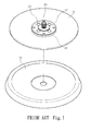
- a common grinding disc comprises a mandrel 10, a supporting disc 11, an upper clamping disc 12, a lower clamping disc 13 and a foam supporting body 14.
- the upper clamping disc 12 and the lower clamping disc 13 are respectively superimposed at two sides of the supporting disc 11.
- the upper clamping disc 12, the lower clamping disc 13 and the supporting disc 11 are assembled and fastened by at least one fastening member 15.
- the mandrel 10 is inserted through the upper clamping disc 12, the lower clamping disc 13 and the supporting disc 11 to complete a semi-manufactured grinding disc.
- the semi-manufactured grinding disc is then placed in a foaming mold, which applies foams on the semi-manufactured grinding disc to form the foam supporting body 14 on the supporting disc 11, thereby completing the grinding disc.
- the grinding plate (not shown) is installed on the foam supporting body 14.
- a counterweight ratio of each structure is adjusted according to the balances during a design process of a common grinding disc. Therefore, grinding disc of all models and sizes have specified and regulated weights.
- the foam supporting body 14 is allotted with only 20% of the total weight of the grinding disc. The foam supporting body 14 is capable of producing appropriate deformation during the grinding process of the grinding machine tool to be closely adhered to the grinding plate on the grinding target.
- the foam supporting body 14 Since the foaming level of the foam supporting body 14 determines the structural strength, the foam supporting body 14 needs to foam at a high level under weight restrictions, such that the foam supporting body 14 has a loose structure that can be easily damaged during the grinding process.
- An over-foamed foam supporting body 14 is similar to a sponge, which cannot produce appropriate deformation according to contours of the grinding target during the grinding process nor quickly restore to a normal state, and is thus not suitable for ideal applications. Further, restrained by the unsatisfactory structural strength of the foam supporting body 14, the grinding machine tool is incapable of performing high-speed grinding operations. During high-speed grinding operations, the foam supporting body 14 may not withstand the centripetal force brought by the high-speed rotations and thus becomes damaged. Therefore, there is a need for an improved grinding disc for providing preferred grinding effects.
- the subject-matter of the present application can overcome in particular the incapability of quickly producing appropriate deformation adapting to grinding requirements due to a unsatisfactory structural strength of a foam supporting body in a conventional grinding disc and a manufacturing method of a conventional grinding disc.
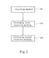
- a method for manufacturing a grinding disc includes the following steps.
- a mandrel is provided.
- the mandrel comprises a bridge section and an embedding section extended from the bridge section.
- a first injection molding step is performed.
- the mandrel is placed in a first injection mold, and the first injection mold at least injects a first injection plastic material on the mandrel.
- the first injection plastic material forms a preliminary carrier disc.
- the preliminary carrier disc comprises a first embedding portion completely encircling the embedding section, and a carrier portion extending towards a periphery of the first embedding portion.
- a second injection molding step is then performed.
- the mandrel embedded with the preliminary carrier disc is placed in a second injection mold, and the second injection mold at least injects the second injection plastic material on the preliminary carrier disc.
- the second injection plastic material forms a secondary carrier disc fixed at the preliminary carrier disc.
- the secondary carrier disc comprises an engaging portion adhered to and supported by the carrier portion, and a mounting surface opposite to the engaging portion.
- the preliminary carrier disc after completing the first injection molding step, further comprises a second embedding portion formed on the carrier portion. Further, after completing the first injection molding step, the secondary carrier disc further comprises a third embedding portion extended from the engaging portion and corresponding to the second embedding portion.
- the first injection plastic material is a mixed plastic material having fiberglass;
- the second injection plastic material is a plastic material made of a group selected from polyurethane, epoxy, unsaturated polyester, and phenol aldehyde.
- the grinding disc according to the present invention can be assembled to a machine tool and be propelled by the machine tool for rotations.
- the grinding disc comprises a mandrel, a preliminary carrier disc formed by an injection plastic material and embedded on the mandrel, and a secondary carrier disc formed by a second injection plastic material and fixed on the preliminary carrier disc.
- the mandrel comprises a bridge section for connecting to the machine tool, and an embedding section extended from the bridge section.
- the preliminary carrier disc comprises a first embedding portion for completely encircling an embedding section of the mandrel, and a carrier portion extending towards the periphery of the first embedding portion.
- the secondary disc comprises the engaging portion adhered to and supported by the carrier portion, and a mounting surface opposite to the engaging portion and for assembling to the grinding plate.
- the preliminary carrier disc further comprises a second embedding portion formed on the carrier portion for increasing an engaging area between the preliminary carrier disc and the second carrier disc.
- the secondary carrier disc further comprises a third embedding portion extended from the engaging portion and for embedding with the second embedding portion. Further, the second embedding section is disposed at a periphery of the carrier portion or neighboring to the first embedding portion.
- the first injection plastic material is a mixed plastic material having fiberglass;
- the second injection plastic material is a plastic material made of a group selected from polyurethane, epoxy, unsaturated polyester, and phenol aldehyde.
- the first injection plastic material and the second injection plastic material are sequentially injected on the mandrel to form the preliminary carrier disc.
- the preliminary carrier disc comprises the first embedding portion for completely encircling the embedding section of the mandrel and the carrier portion extending towards the periphery of the first embedding portion.
- the second plastic material is then injected on the preliminary carrier disc to form the secondary carrier disc.
- the secondary disc comprises the engaging portion adhered to and supported by the carrier portion, and the mounting surface opposite to the engaging portion and for assembling to the grinding plate. Therefore, compared to a conventional grinding disc, the grinding disc of the present invention features the advantages below.
- the preliminary carrier disc is lighter in overall weight.
- the preliminary carrier disc is formed by injection of the first injection plastic material on the mandrel and has a weight far lighter than the weight of the structure of a conventional grinding disc formed by the upper clamping disc, the lower clamping disc and the supporting disc, the secondary carrier disc is allotted with a greater percentage in the overall weight of the grinding disc.
- the secondary carrier disc offers preferred structural strength. Since the secondary carrier disc of the present invention is made of a non-foaming material and occupies a greater percentage in the overall weight, the structural strength and ductility of the secondary carrier disc can be increased. Thus, the secondary carrier disc is allowed to more closely conform and be in closer contact with the grinding target, and can be implemented to machine tools operating at high rotational speeds to yield preferred grinding effects.
- a disc according to the present invention is configured to be assembled to a machine tool (not shown) and to be propelled by the machine tool for rotations, such that a grinding plate assembled on the grinding disc is allowed to perform grinding operations.
- the grinding disc is formed by a first injection plastic material and a second injection plastic material injected in sequence. More specifically, the method for manufacturing the grinding disc is described in detail with reference to FIGS. 2 to 4 .
- a mandrel 20 provided comprises a bridge section 201 and an embedding section 202 extending from the bridge section 201. More specifically, the mandrel 20 is for connecting to the machine tool, and is assembled to the machine tool via the bridge section 201.
- a first injection mold step is performed.
- the mandrel 20 is placed in a first injection mold (not shown), and the first injection mold at least injects the first injection plastic material on the mandrel 20.
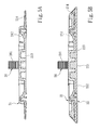
- the first injection plastic material forms a preliminary carrier disc 21, as shown in FIG. 5A .
- the preliminary carrier plate 21 comprises a first embedding portion 211 for completely encircling the embedding section 202, and a carrier portion 212 extending towards a periphery of the first embedding portion 211.
- the first injection plastic material is a mixed plastic material having fiberglass.
- a second injection mold step is performed.
- the mandrel 20 embedded with the preliminary carrier disc 21 is placed in a second injection mold, and the second injection mold at least injects the second injection plastic material on the preliminary carrier disc 21.
- the second injection plastic material forms a secondary carrier disc 22 fixed at the preliminary carrier disc 21, as shown in FIG. 5B .
- the secondary carrier disc 22 comprises an engaging portion 221 adhered to and supported by the carrier portion 212, and a mounting surface 222 opposite to the engaging portion 221.
- the second injection plastic material may be a plastic material as a group selected from polyurethane, epoxy, unsaturated polyester, and phenol aldehyde.
- the manufactured grinding disc may be assembled to the machine tool 30 via the bridge section 201 of the mandrel 20, and the grinding plate 40 may be assembled via the mounting surface 222 at the secondary carrier disc 22.
- the preliminary carrier disc 21 weighs less than the assembly formed by the supporting disc 11, the upper clamping disc 12 and the lower clamping disc 13 (in FIG. 1 ) of a conventional grinding disc.
- the weight of the secondary carrier disc 22 can be increased to accordingly reinforce the structural strength and ductility of the secondary carrier disc 22.
- the ductility of the secondary carrier disc 22 ensures that the mounting surface 222 conforms and comes into complete contact with the grinding target, so as to quickly provide appropriate deformation according to the contours of the grinding target.
- the secondary carrier disc 22 Compared to the foam supporting body 14 (in FIG. 1 ) conventionally formed by foaming, the secondary carrier disc 22 has preferred structural strength to offer not only preferred ductility but also greater resilience to damages during grinding operations. Further, as the structural strength of the secondary carrier disc 22 can withstand a greater eccentric force, the grinding disc of the present invention can be ideally applied to machine tools rotating at a greater speed to yield even better grinding effects.
- the injected and formed preliminary carrier disc 21 further comprises a second embedding portion 213 formed on the carrier portion 212.
- the second embedding portion 213 is for increasing an engaging area of the secondary carrier disc 22 to allow the preliminary carrier disc 21 to be more closely adhered to the secondary carrier disc 22.
- the secondary carrier disc 22 further comprises a third embedding portion 223 extended from the engaging portion 221 and corresponding to the second embedding portion 213. More specifically, the third embedding portion 223 is formed by the second injection plastic material injected on the second embedding portion 213.
- a position of the second embedding portion 213 may be adjusted according to actual design requirements.
- the second embedding portion 213 may be disposed neighboring to the first embedding portion 211 ( FIG. 3 ).
- the second embedding portion 214 is disposed at the periphery of the carrier portion 212
- the third embedding portion 223 is disposed correspondingly to the second embedding portion (213 or 214).
- the first injection plastic material and the second injection plastic material are sequentially injected on the mandrel to form the preliminary carrier disc.
- the preliminary carrier disc comprises the first embedding portion for completely encircling the embedding section of the mandrel, and the carrier portion extending towards the periphery of the first embedding portion.
- the second plastic material is then injected on the preliminary carrier disc to form the secondary carrier disc.
- the secondary disc comprises the engaging portion adhered to and supported by the carrier portion, and the mounting surface opposite to the engaging portion and for assembling to the grinding plate.
- the present invention is effectively overcomes the incapability of quickly producing appropriate deformation adapting to grinding requirements due weight restrictions and unsatisfactory structural strength of a foam supporting body of a conventional grinding disc. Therefore, the grinding disc and the method for manufacturing the grinding disc can adaptively produce appropriate deformation according to contours of the grinding target, and can be implemented in high-speed grinding machine tools.
Landscapes
- Engineering & Computer Science (AREA)
- Mechanical Engineering (AREA)
- Manufacturing & Machinery (AREA)
- Manufacturing Of Magnetic Record Carriers (AREA)
Priority Applications (1)
| Application Number | Priority Date | Filing Date | Title |
|---|---|---|---|
| EP12197753.2A EP2746027A1 (fr) | 2012-12-18 | 2012-12-18 | Disque de meulage et procédé de fabrication dudit disque |
Applications Claiming Priority (1)
| Application Number | Priority Date | Filing Date | Title |
|---|---|---|---|
| EP12197753.2A EP2746027A1 (fr) | 2012-12-18 | 2012-12-18 | Disque de meulage et procédé de fabrication dudit disque |
Publications (1)
| Publication Number | Publication Date |
|---|---|
| EP2746027A1 true EP2746027A1 (fr) | 2014-06-25 |
Family
ID=47559143
Family Applications (1)
| Application Number | Title | Priority Date | Filing Date |
|---|---|---|---|
| EP12197753.2A Withdrawn EP2746027A1 (fr) | 2012-12-18 | 2012-12-18 | Disque de meulage et procédé de fabrication dudit disque |
Country Status (1)
| Country | Link |
|---|---|
| EP (1) | EP2746027A1 (fr) |
Cited By (1)
| Publication number | Priority date | Publication date | Assignee | Title |
|---|---|---|---|---|
| US20150283675A1 (en) * | 2014-04-04 | 2015-10-08 | Campana Mirco E Figli S.N.C. | Disc for power tools for supporting abrasive material and abrasive disc comprising said support |
Citations (6)
| Publication number | Priority date | Publication date | Assignee | Title |
|---|---|---|---|---|
| US2581567A (en) * | 1948-12-29 | 1952-01-08 | Darrell R Wiley | Buffer backing pad |
| US3333371A (en) * | 1966-04-29 | 1967-08-01 | Carborundum Co | Non-foamed polyurethane sander pad for abrasive discs |
| DE3030942A1 (de) * | 1980-08-16 | 1982-05-19 | Festo-Maschinenfabrik Gottlieb Stoll, 7300 Esslingen | Schleifschuh, insbesondere fuer handschleifgeraete |
| US4830807A (en) * | 1986-07-14 | 1989-05-16 | Warren William L | Method of making a mounting disk for a floor polisher |
| US6136143A (en) * | 1998-02-23 | 2000-10-24 | 3M Innovative Properties Company | Surface treating article including a hub |
| US20050124275A1 (en) * | 2003-12-06 | 2005-06-09 | Steffen Wuensch | Abrasive pad for a manual grinding machine |
-
2012
- 2012-12-18 EP EP12197753.2A patent/EP2746027A1/fr not_active Withdrawn
Patent Citations (6)
| Publication number | Priority date | Publication date | Assignee | Title |
|---|---|---|---|---|
| US2581567A (en) * | 1948-12-29 | 1952-01-08 | Darrell R Wiley | Buffer backing pad |
| US3333371A (en) * | 1966-04-29 | 1967-08-01 | Carborundum Co | Non-foamed polyurethane sander pad for abrasive discs |
| DE3030942A1 (de) * | 1980-08-16 | 1982-05-19 | Festo-Maschinenfabrik Gottlieb Stoll, 7300 Esslingen | Schleifschuh, insbesondere fuer handschleifgeraete |
| US4830807A (en) * | 1986-07-14 | 1989-05-16 | Warren William L | Method of making a mounting disk for a floor polisher |
| US6136143A (en) * | 1998-02-23 | 2000-10-24 | 3M Innovative Properties Company | Surface treating article including a hub |
| US20050124275A1 (en) * | 2003-12-06 | 2005-06-09 | Steffen Wuensch | Abrasive pad for a manual grinding machine |
Cited By (1)
| Publication number | Priority date | Publication date | Assignee | Title |
|---|---|---|---|---|
| US20150283675A1 (en) * | 2014-04-04 | 2015-10-08 | Campana Mirco E Figli S.N.C. | Disc for power tools for supporting abrasive material and abrasive disc comprising said support |
Similar Documents
| Publication | Publication Date | Title |
|---|---|---|
| US20140179205A1 (en) | Grinding disc and method for manufacturing the same | |
| US9018817B2 (en) | Retaining bands | |
| EP2985140B1 (fr) | Elément d'habillage pour sol de véhicule | |
| US9162597B2 (en) | Seat armrest frame | |
| EP3571112B1 (fr) | Renfort de pilier | |
| EP3688559B1 (fr) | Couvercle de verre d'un dispositif the communication mobile | |
| EP2746027A1 (fr) | Disque de meulage et procédé de fabrication dudit disque | |
| US9694731B2 (en) | Vehicle interior storage compartment | |
| CN210852297U (zh) | 磁体紧固件总成及其基座 | |
| CN105840463A (zh) | 一种压缩机防震套件 | |
| US10566588B2 (en) | Battery cell support assembly | |
| JP6213661B2 (ja) | 輸送機器用部品およびパネル部材 | |
| CN201113636Y (zh) | 电机减振装置 | |
| CN205835061U (zh) | 一种弧形打磨头及其打磨机 | |
| KR20190099896A (ko) | 조향핸들 박피 장치 및 방법 | |
| US20190093675A1 (en) | Centrifugal compressor | |
| JP2000326197A (ja) | ドライサーフェーサー | |
| TWM480441U (zh) | 研磨盤結構 | |
| JP3996547B2 (ja) | ゴルフクラブヘッドとその製造方法 | |
| CN208158398U (zh) | 一种新型音圈马达载体 | |
| JP2012236285A (ja) | 衝撃吸収パッドの製造方法、および衝撃吸収パッド | |
| CN106130246A (zh) | 一种电机减震底座 | |
| CN113306071A (zh) | 利用发泡注射成型的汽车悬架装置用弹簧垫制造方法 | |
| CN211975762U (zh) | 一种无人机飞控及其减震装置 | |
| CN203696637U (zh) | 双砂轮车轴磨削装置 |
Legal Events
| Date | Code | Title | Description |
|---|---|---|---|
| PUAI | Public reference made under article 153(3) epc to a published international application that has entered the european phase |
Free format text: ORIGINAL CODE: 0009012 |
|
| 17P | Request for examination filed |
Effective date: 20121218 |
|
| AK | Designated contracting states |
Kind code of ref document: A1 Designated state(s): AL AT BE BG CH CY CZ DE DK EE ES FI FR GB GR HR HU IE IS IT LI LT LU LV MC MK MT NL NO PL PT RO RS SE SI SK SM TR |
|
| AX | Request for extension of the european patent |
Extension state: BA ME |
|
| STAA | Information on the status of an ep patent application or granted ep patent |
Free format text: STATUS: THE APPLICATION IS DEEMED TO BE WITHDRAWN |
|
| 18D | Application deemed to be withdrawn |
Effective date: 20150106 |