EP2746030B1 - Étoile réductrice pour le transport de récipients en matière synthétique - Google Patents
Étoile réductrice pour le transport de récipients en matière synthétique Download PDFInfo
- Publication number
- EP2746030B1 EP2746030B1 EP13199205.9A EP13199205A EP2746030B1 EP 2746030 B1 EP2746030 B1 EP 2746030B1 EP 13199205 A EP13199205 A EP 13199205A EP 2746030 B1 EP2746030 B1 EP 2746030B1
- Authority
- EP
- European Patent Office
- Prior art keywords
- drive
- movement
- plastics material
- material containers
- drive element
- Prior art date
- Legal status (The legal status is an assumption and is not a legal conclusion. Google has not performed a legal analysis and makes no representation as to the accuracy of the status listed.)
- Revoked
Links
Images


Classifications
-
- B—PERFORMING OPERATIONS; TRANSPORTING
- B29—WORKING OF PLASTICS; WORKING OF SUBSTANCES IN A PLASTIC STATE IN GENERAL
- B29C—SHAPING OR JOINING OF PLASTICS; SHAPING OF MATERIAL IN A PLASTIC STATE, NOT OTHERWISE PROVIDED FOR; AFTER-TREATMENT OF THE SHAPED PRODUCTS, e.g. REPAIRING
- B29C49/00—Blow-moulding, i.e. blowing a preform or parison to a desired shape within a mould; Apparatus therefor
- B29C49/42—Component parts, details or accessories; Auxiliary operations
- B29C49/4252—Auxiliary operations prior to the blow-moulding operation not otherwise provided for
-
- B—PERFORMING OPERATIONS; TRANSPORTING
- B29—WORKING OF PLASTICS; WORKING OF SUBSTANCES IN A PLASTIC STATE IN GENERAL
- B29C—SHAPING OR JOINING OF PLASTICS; SHAPING OF MATERIAL IN A PLASTIC STATE, NOT OTHERWISE PROVIDED FOR; AFTER-TREATMENT OF THE SHAPED PRODUCTS, e.g. REPAIRING
- B29C49/00—Blow-moulding, i.e. blowing a preform or parison to a desired shape within a mould; Apparatus therefor
- B29C49/28—Blow-moulding apparatus
-
- B—PERFORMING OPERATIONS; TRANSPORTING
- B29—WORKING OF PLASTICS; WORKING OF SUBSTANCES IN A PLASTIC STATE IN GENERAL
- B29C—SHAPING OR JOINING OF PLASTICS; SHAPING OF MATERIAL IN A PLASTIC STATE, NOT OTHERWISE PROVIDED FOR; AFTER-TREATMENT OF THE SHAPED PRODUCTS, e.g. REPAIRING
- B29C49/00—Blow-moulding, i.e. blowing a preform or parison to a desired shape within a mould; Apparatus therefor
- B29C49/42—Component parts, details or accessories; Auxiliary operations
- B29C49/4205—Handling means, e.g. transfer, loading or discharging means
- B29C49/42073—Grippers
-
- B—PERFORMING OPERATIONS; TRANSPORTING
- B29—WORKING OF PLASTICS; WORKING OF SUBSTANCES IN A PLASTIC STATE IN GENERAL
- B29C—SHAPING OR JOINING OF PLASTICS; SHAPING OF MATERIAL IN A PLASTIC STATE, NOT OTHERWISE PROVIDED FOR; AFTER-TREATMENT OF THE SHAPED PRODUCTS, e.g. REPAIRING
- B29C49/00—Blow-moulding, i.e. blowing a preform or parison to a desired shape within a mould; Apparatus therefor
- B29C49/42—Component parts, details or accessories; Auxiliary operations
- B29C49/4205—Handling means, e.g. transfer, loading or discharging means
- B29C49/42093—Transporting apparatus, e.g. slides, wheels or conveyors
- B29C49/42095—Rotating wheels or stars
-
- B—PERFORMING OPERATIONS; TRANSPORTING
- B29—WORKING OF PLASTICS; WORKING OF SUBSTANCES IN A PLASTIC STATE IN GENERAL
- B29C—SHAPING OR JOINING OF PLASTICS; SHAPING OF MATERIAL IN A PLASTIC STATE, NOT OTHERWISE PROVIDED FOR; AFTER-TREATMENT OF THE SHAPED PRODUCTS, e.g. REPAIRING
- B29C49/00—Blow-moulding, i.e. blowing a preform or parison to a desired shape within a mould; Apparatus therefor
- B29C49/42—Component parts, details or accessories; Auxiliary operations
- B29C49/46—Component parts, details or accessories; Auxiliary operations characterised by using particular environment or blow fluids other than air
-
- B—PERFORMING OPERATIONS; TRANSPORTING
- B29—WORKING OF PLASTICS; WORKING OF SUBSTANCES IN A PLASTIC STATE IN GENERAL
- B29C—SHAPING OR JOINING OF PLASTICS; SHAPING OF MATERIAL IN A PLASTIC STATE, NOT OTHERWISE PROVIDED FOR; AFTER-TREATMENT OF THE SHAPED PRODUCTS, e.g. REPAIRING
- B29C49/00—Blow-moulding, i.e. blowing a preform or parison to a desired shape within a mould; Apparatus therefor
- B29C49/42—Component parts, details or accessories; Auxiliary operations
- B29C49/46—Component parts, details or accessories; Auxiliary operations characterised by using particular environment or blow fluids other than air
- B29C2049/4673—Environments
- B29C2049/4697—Clean room
-
- B—PERFORMING OPERATIONS; TRANSPORTING
- B29—WORKING OF PLASTICS; WORKING OF SUBSTANCES IN A PLASTIC STATE IN GENERAL
- B29C—SHAPING OR JOINING OF PLASTICS; SHAPING OF MATERIAL IN A PLASTIC STATE, NOT OTHERWISE PROVIDED FOR; AFTER-TREATMENT OF THE SHAPED PRODUCTS, e.g. REPAIRING
- B29C49/00—Blow-moulding, i.e. blowing a preform or parison to a desired shape within a mould; Apparatus therefor
- B29C49/42—Component parts, details or accessories; Auxiliary operations
- B29C49/46—Component parts, details or accessories; Auxiliary operations characterised by using particular environment or blow fluids other than air
- B29C2049/4673—Environments
- B29C2049/4698—Pressure difference, e.g. over pressure in room
-
- B—PERFORMING OPERATIONS; TRANSPORTING
- B29—WORKING OF PLASTICS; WORKING OF SUBSTANCES IN A PLASTIC STATE IN GENERAL
- B29C—SHAPING OR JOINING OF PLASTICS; SHAPING OF MATERIAL IN A PLASTIC STATE, NOT OTHERWISE PROVIDED FOR; AFTER-TREATMENT OF THE SHAPED PRODUCTS, e.g. REPAIRING
- B29C49/00—Blow-moulding, i.e. blowing a preform or parison to a desired shape within a mould; Apparatus therefor
- B29C49/28—Blow-moulding apparatus
- B29C49/30—Blow-moulding apparatus having movable moulds or mould parts
- B29C49/36—Blow-moulding apparatus having movable moulds or mould parts rotatable about one axis
-
- B—PERFORMING OPERATIONS; TRANSPORTING
- B29—WORKING OF PLASTICS; WORKING OF SUBSTANCES IN A PLASTIC STATE IN GENERAL
- B29C—SHAPING OR JOINING OF PLASTICS; SHAPING OF MATERIAL IN A PLASTIC STATE, NOT OTHERWISE PROVIDED FOR; AFTER-TREATMENT OF THE SHAPED PRODUCTS, e.g. REPAIRING
- B29C49/00—Blow-moulding, i.e. blowing a preform or parison to a desired shape within a mould; Apparatus therefor
- B29C49/42—Component parts, details or accessories; Auxiliary operations
- B29C49/4205—Handling means, e.g. transfer, loading or discharging means
- B29C49/42073—Grippers
- B29C49/42085—Grippers holding inside the neck
-
- B—PERFORMING OPERATIONS; TRANSPORTING
- B29—WORKING OF PLASTICS; WORKING OF SUBSTANCES IN A PLASTIC STATE IN GENERAL
- B29C—SHAPING OR JOINING OF PLASTICS; SHAPING OF MATERIAL IN A PLASTIC STATE, NOT OTHERWISE PROVIDED FOR; AFTER-TREATMENT OF THE SHAPED PRODUCTS, e.g. REPAIRING
- B29C49/00—Blow-moulding, i.e. blowing a preform or parison to a desired shape within a mould; Apparatus therefor
- B29C49/42—Component parts, details or accessories; Auxiliary operations
- B29C49/4205—Handling means, e.g. transfer, loading or discharging means
- B29C49/42113—Means for manipulating the objects' position or orientation
- B29C49/42117—Translation e.g. telescopic movement to pick up a preform
-
- B—PERFORMING OPERATIONS; TRANSPORTING
- B29—WORKING OF PLASTICS; WORKING OF SUBSTANCES IN A PLASTIC STATE IN GENERAL
- B29C—SHAPING OR JOINING OF PLASTICS; SHAPING OF MATERIAL IN A PLASTIC STATE, NOT OTHERWISE PROVIDED FOR; AFTER-TREATMENT OF THE SHAPED PRODUCTS, e.g. REPAIRING
- B29C49/00—Blow-moulding, i.e. blowing a preform or parison to a desired shape within a mould; Apparatus therefor
- B29C49/42—Component parts, details or accessories; Auxiliary operations
- B29C49/42403—Purging or cleaning the blow-moulding apparatus
- B29C49/42405—Sterilizing
-
- B—PERFORMING OPERATIONS; TRANSPORTING
- B29—WORKING OF PLASTICS; WORKING OF SUBSTANCES IN A PLASTIC STATE IN GENERAL
- B29C—SHAPING OR JOINING OF PLASTICS; SHAPING OF MATERIAL IN A PLASTIC STATE, NOT OTHERWISE PROVIDED FOR; AFTER-TREATMENT OF THE SHAPED PRODUCTS, e.g. REPAIRING
- B29C49/00—Blow-moulding, i.e. blowing a preform or parison to a desired shape within a mould; Apparatus therefor
- B29C49/42—Component parts, details or accessories; Auxiliary operations
- B29C49/42407—Procedures for start-up or material change
-
- B—PERFORMING OPERATIONS; TRANSPORTING
- B29—WORKING OF PLASTICS; WORKING OF SUBSTANCES IN A PLASTIC STATE IN GENERAL
- B29C—SHAPING OR JOINING OF PLASTICS; SHAPING OF MATERIAL IN A PLASTIC STATE, NOT OTHERWISE PROVIDED FOR; AFTER-TREATMENT OF THE SHAPED PRODUCTS, e.g. REPAIRING
- B29C49/00—Blow-moulding, i.e. blowing a preform or parison to a desired shape within a mould; Apparatus therefor
- B29C49/42—Component parts, details or accessories; Auxiliary operations
- B29C49/4268—Auxiliary operations during the blow-moulding operation
-
- B—PERFORMING OPERATIONS; TRANSPORTING
- B29—WORKING OF PLASTICS; WORKING OF SUBSTANCES IN A PLASTIC STATE IN GENERAL
- B29C—SHAPING OR JOINING OF PLASTICS; SHAPING OF MATERIAL IN A PLASTIC STATE, NOT OTHERWISE PROVIDED FOR; AFTER-TREATMENT OF THE SHAPED PRODUCTS, e.g. REPAIRING
- B29C49/00—Blow-moulding, i.e. blowing a preform or parison to a desired shape within a mould; Apparatus therefor
- B29C49/42—Component parts, details or accessories; Auxiliary operations
- B29C49/4273—Auxiliary operations after the blow-moulding operation not otherwise provided for
- B29C49/42808—Filling the article
-
- B—PERFORMING OPERATIONS; TRANSPORTING
- B29—WORKING OF PLASTICS; WORKING OF SUBSTANCES IN A PLASTIC STATE IN GENERAL
- B29C—SHAPING OR JOINING OF PLASTICS; SHAPING OF MATERIAL IN A PLASTIC STATE, NOT OTHERWISE PROVIDED FOR; AFTER-TREATMENT OF THE SHAPED PRODUCTS, e.g. REPAIRING
- B29C49/00—Blow-moulding, i.e. blowing a preform or parison to a desired shape within a mould; Apparatus therefor
- B29C49/42—Component parts, details or accessories; Auxiliary operations
- B29C49/64—Heating or cooling preforms, parisons or blown articles
- B29C49/6409—Thermal conditioning of preforms
- B29C49/6418—Heating of preforms
Definitions
- the present invention relates to a device for transporting containers and in particular plastic containers.
- Such devices have long been known from the prior art. It is also known to use such transport devices, for example, to transport plastic preforms within a blow molding machine from a heating device, such as a furnace, to a forming device, such as a blowing wheel. In these transports, it is advantageous if a pitch between the transported plastic containers can be changed.
- Plastic containers can be understood as meaning both plastic preforms and plastic bottles.
- the present invention is therefore based on the object to provide a transport device for transporting containers, which is particularly suitable for aseptic applications.
- the drive device has a first drive element for generating a first movement with a first movement direction, and a second drive element for generating a second movement with a second movement direction, the first movement direction and the second movement direction differing from one another.
- both movements to be, for example, pivoting movements, but in this case, in particular, pivoting movements with different angles or different radii, or also pivoting movements with respect to different pivot axes, but preferably these pivot axes are parallel to one another.
- a direction of movement is understood to mean any direction of movement in space and, in particular, the direction of movement is selected from a group of directions of movement which comprise linear movements in a predetermined direction, movements along a circular (segment) path, movements along an elliptical path and the like ,
- a movement along a circular path and a linear movement are considered as different movements.
- movements along orbits of different radii become different Understood movements.
- the term of the movement path can also be used instead of the term of the movement direction, ie the movement path generated by the first drive device differs from the movement path generated by the second drive device. Decisive are therefore not (only) certain (end) points of the movement but the path or the course between these (end) points.
- the first drive element is controllable independently of the second drive element.
- the carrier In the mentioned axis of rotation, with respect to which the carrier is rotatable, it is in particular a vertical or converging to the center of the earth axis of rotation. Therefore, the containers are transported in particular in a horizontal plane.
- the axis of rotation is slightly inclined, for example by up to 5 ° relative to this vertical direction.
- the sterile room surrounds the transport path of the plastic containers like a channel. It is possible that the carrier, or a part of the carrier also forms one of said walls, which delimit the sterile room.
- a drive device which drives the carrier to its rotational movement, arranged outside of the sterile room or clean room.
- this drive device is an electric motor.
- the device has a pressurization device to pressurize the sterile room with an overpressure relative to an ambient pressure.
- the holding elements are gripping clamps, which grip the containers, for example below their support ring or in a region between the support ring and the thread.
- the retaining elements may also be formed as mandrels, which are insertable into the mouths of the containers to be transported.
- the holding elements are controllable holding elements, ie holding elements that are switchable between a first position in which they can grip the containers and a second position in which the containers are not gripped or released.
- both drive elements are selected from a group of drive elements, which contains electromotive drive elements, pneumatic drive elements, hydraulic drive elements and the like.
- the movement generated by the first drive element is advantageously coupled to the movement generated by the second drive element, such that a movement of the holding element also results from a superimposition of these movements.
- the movement of the holding elements is also effected by a coupling of the two, in particular motor drives.
- the two, in particular motor drives are also effected by a coupling of the two, in particular motor drives.
- the clean room or sterile room is sterilized with a tempered gas mixture of hydrogen peroxide and air. Cleaning is not necessarily required before every sterilization - especially of plastic preforms.
- the plastic containers which are in particular plastic preforms, are advantageously transported between an oven and a blowing wheel by means of at least two, preferably by means of three treatment stars and / or optionally sterilized.
- a further device is provided between the furnace and the blowing wheel, which sterilizes the plastic preforms by exposure to hydrogen peroxide or a hydrogen peroxide-air mixture or electron radiation.
- the clean room is subjected to filtered air, so that an overpressure is ensured to the surrounding atmosphere.
- An advantageous container production is ensured, for example, by the pressure ratios p1>p2> p at .
- the value p1 denotes a pressure within a forming device for forming the plastic preforms to the plastic containers
- the value p2 a pressure in the range of the transport device according to the invention and the value of an atmospheric pressure in the environment.
- the ventilation device can also supply other clean rooms of machines, such as a filling machine, a sealing machine or parallel systems.
- the process technology is preferably combined in combination with other machines of container treatment.
- To clean the device can be provided both cleaning and stationary cleaning elements such as cleaning nozzles.
- a pressure between the clean room and the respective drive element which is smaller than a pressure in adjacent areas of the clean room, such as a forming device, so as to prevent the cleaning medium also gets into neighboring plant parts.
- a pressure could be kept at least during the cleaning under an atmospheric pressure.
- At least one drive element is arranged at least partially outside the clean room.
- the two drives are coupled with each other in terms of control technology. This means that they can be controlled independently of each other, while a control device which controls a drive element also in response to the movement of the other drive element.
- the drive elements are fully automatically controlled by an appropriate control.
- At least one drive element is arranged at least partially outside the clean room. It is possible and preferred that the drive element is arranged geometrically outside the clean room. However, it would also be possible for the drive element to be arranged geometrically within the clean room, but there it is arranged, for example, in an encapsulated or closed housing.
- a movement of the drive elements is transmitted through a sterile room boundary of the clean room or a wall bounding the clean room.
- at least one drive element is arranged completely outside the clean room. In a further preferred embodiment, both drive elements are arranged at least partially and preferably completely outside the clean room.
- linear actuators can be separated from the sterile room by means of bellows.
- water lock for sealing the rotational movement of the wearer, which has a circumferential, liquid-filled channel into which another element, such as a sword dips, so as to effect a seal of the clean room.
- control devices may be provided for the individual drive elements, such as converters and the like.
- Such control means may, for example, be housed in housings which are preferably disposed on the support of the apparatus and thus rotate about the major axis of the apparatus, i. the axis of rotation with respect to which all holding devices are rotatable.
- a gear can be arranged to the drive.
- the main axis or main shaft is driven by means of a hollow shaft motor.
- Elements of the drive elements such as the motors, their cables and / or their inverters are preferably located outside the clean room.
- the drive elements can also be designed as part-turn actuators. It is possible that a magnetic field of the respective drive element extends only partially around the minor axes.
- the device according to the invention can be used, for example, to change a distance of the containers and to allow an accompanying transfer between the individual treatment machines.
- rapid transfer between a heating device or an oven and a blowing station can be ensured with the transport device, which is designed in particular as a (division) warping star. In this way, a temperature influence on the mouth of the container and thus an undesirable deformation of this mouth portion of the containers can be prevented.
- the plant can be sterilized or cleaned before a production start. It is also possible that after the production of the containers, the clean room is cleaned, for example, with lye or one or more spray nozzles and / or rotary heads and then rinsed with water, preferably water with drinking water quality. In addition, then the area can still be dried and the system then be put into a resting state.
- the said elements to be sterilized are heated during this sterilization.
- the transport device comprises a pipe system, in which tempered air can be introduced. After this heating, the device can be dry-sterilized, for example with hydrogen peroxide.
- the device according to the invention has a cleaning device for cleaning the transport device, in particular to perform a so-called CIP (cleaning in place) cleaning.
- CIP cleaning in place
- the device has at least one sealing device by means of which the transmission of the movement generated by at least one drive element into the interior of the housing can be sealed off.
- a bellows may be provided, which preferably allows a movement of a drive element in different drive directions.
- At least one drive element generates a pivoting movement of the holding element relative to the carrier. It is possible that the holding element by a predetermined angle, for example, by an angle of 180 °, is pivotable.
- the pivoting of the holding element with respect to the carrier with respect to an axis is given, which is parallel to the axis of rotation of the carrier.
- the device has a coupling element which couples the movement generated by the first drive element with the movement generated by a second drive element.
- a coupling element which couples the movement generated by the first drive element with the movement generated by a second drive element.
- the first drive element a boom and on this boom, in turn, the second drive element can be arranged. It would also be possible for the two drive elements to act on a common element and thus the position of this element can be adjusted or changed by a movement of both drive elements.
- the drive elements can be electrical drive elements, such as electric motors, for example, and the motors themselves, preferably also their cables and any converters, are arranged outside the clean room.
- At least one, preferably more and more preferably all bearing elements are separated from the clean room by seals.
- electrical connections, in particular cables are also guided by hollow shafts. It is possible that the respective cavities of these waves, although they are geometrically within the clean room, are non-sterile.
- At least one drive element is a rotary drive or a linear drive. It is possible that two rotary drives are provided, it would be possible that two linear drives are provided and it would also be possible that a rotary and a linear drive are provided. It is possible that the linear drive generates a movement which is perpendicular to the axis of rotation of the carrier. In this case, this movement is preferably in a radial direction of the carrier, wherein it is also conceivable that the movement is perpendicular to this radial direction of the carrier and also perpendicular to the axis of rotation of the carrier.
- the present invention is further directed to an arrangement for treating plastic containers having a first processing unit which treats the plastic containers in a first predetermined manner. Furthermore, the arrangement has a second treatment unit following this first treatment unit in a transport direction of the plastic containers, wherein a device of the type described above is arranged between the first treatment unit and the second treatment unit, which transports the plastic containers from the first treatment unit to the second treatment unit.
- the clean room of the transport device also extends to at least one of the two treatment units, in particular at least to the treatment unit downstream treatment unit and particularly preferably to both treatment units.
- the sterilization units have radiation devices which act on the containers with radiation, for example electron radiation, UV radiation, X-radiation or the like.
- media such as hydrogen peroxide or peracetic acid. That's it
- the sterilization device it is possible for the sterilization device to have a multiplicity of beam fingers arranged on a carrier, which can be introduced into the containers.
- the transport device described here is suitable for different container treatment devices and machines, such as, for example, treatment machines for sterilizing the containers or sorting systems.
- a transport device described above is suitable for applications in which it is expedient to change the distance of the plastic preforms or plastic containers, in particular between rotary, container treatment machines.
- the arrangement may be a sterilizer which initially sterilizes plastic preforms by means of electron radiation.
- a relatively small distance of, for example, 50 mm between the individual plastic preforms is advantageous to carry out their external treatment.
- the distance should be increased to at least 100 mm for structural reasons. It would also be possible to use the transport device according to the invention for changing molds in a stretch blow molding machine.
- the present invention further relates to a method for treating plastic containers.
- the plastic containers are treated by means of a first treatment unit in a first predetermined manner and the plastic containers are then transported individually by means of a transport device to a second treatment unit, wherein the plastic containers are held with a plurality of arranged on a rotatable support of the transport means holding means and the plastic containers of this second treatment unit are treated in a second way, which preferably differs from the first one.
- the plastic containers are transported during their transport with the transport device within a clean room and this clean room is delimited by means of at least one wall against an unsterile environment.
- a distance between two successive plastic containers in the transport device is changed during the transport of the plastic containers with the transport device.
- the plastic containers are plastic preforms.
- At least one plastic container is pivoted or moved during its transport relative to the rotatable carrier.
- this movement of the plastic containers is generated by means of two associated with the respective holding devices drives.
- these are motor drives and in particular electromotive drives.
- this relative movement between the holding devices and their carrier or their drive elements is sealed.
- the holding device or the holding element with the container arranged thereon can be permanently located inside the clean room and the drive assigned to it or the drive element itself can be located outside the clean room.
- the plastic containers are thereby moved in sections during their transport with the transport device on a circular transport path.
- At least one of the two treatment units performs a sterilization process and / or a cleaning process on the plastic containers.
- the other treatment unit also performs a sterilization process on the containers.
- these may also be other treatment units, for example a heating unit which heats the plastic preforms, a forming unit, such as a stretch blow molding machine, which converts the plastic preforms into plastic bottles, a flushing device, a filling device, a labeling device or the like.
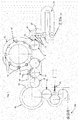
- Fig. 1 shows a plant 100 according to the invention, more precisely an aseptic system for the production of plastic containers and the filling of liquids, such as drinks, in these containers.
- This plant 100 in this case has a stretch blow molding machine 40, which has a rotatable support 44, or a blowing wheel 44, on which a plurality of transformation stations 42 is arranged. These blow stations in this case have a predetermined distance in the circumferential direction to each other.
- the conversion stations 42 can rotate on the one hand by attachment to a blowing wheel 44 or on the other hand also be arranged stationary.
- the forming device 40 is preceded by a treatment unit designated in its entirety by 50, more precisely a sterilization unit.
- This sterilization unit 50 here has three transport devices or treatment stars 16, which transport the plastic preforms or the plastic containers 10 during their sterilization. This is done here a sterilization of the plastic containers before the actual blowing or forming process.
- the system here has three transport devices 1 according to the invention.
- One of these transport devices 1 is arranged at the input of the forming device 40, a further device 1 is arranged at the outlet of the forming device 40 and a third device 1 is arranged between a heating device 70 for heating the plastic preforms and the sterilization unit 50.
- a heating device 70 for heating the plastic preforms and the sterilization unit 50 is arranged between a heating device 70 for heating the plastic preforms and the sterilization unit 50.
- the plastic preforms 10 are supplied to the heating device 70 and heated there to a forming temperature, that is to a temperature at which a forming process can be carried out.
- the plastic preforms are expanded by applying blown air to the plastic containers.
- the individual forming stations 42 each have blow molds that can be unfolded and folded to accommodate the plastic preforms in a cavity formed by the blow molds and to expand the plastic preforms against the walls of these blow molds.
- a further sterilization unit 60 which may also have a plurality of transport stars 32, 34.
- the now completed plastic containers are sterilized before they are filled. It is possible that this sterilization unit has jet fingers which can be inserted into the interior of the now manufactured plastic containers.
- a sterilization of the plastic containers by means of a sterilization medium, such as hydrogen peroxide or peracetic acid can also be done here.
- even more sterilization units and / or transfer areas could be provided.
- the reference numeral 80 refers to a filling device which fills the finished containers with a liquid. It can be seen that the entire treatment of the plastic preforms takes place up to the filling process in a clean room 20. Therefore, in particular, the forming device 40 is designed for forming the plastic preforms in plastic containers as aseptic conditioning, which allows expansion of the plastic preforms to the plastic containers under sterile conditions. The clean room 20 thus also extends in the region of this forming device 40. In this sterile forming device 40, the pre-tempered plastic preforms are thus formed into the finished containers 10a.
- the preferably likewise aseptically filled product is dispensed in the now closed containers 10a.
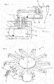
- Fig. 2 shows a first embodiment of a transport device according to the invention 1.
- This transport device performs here two rotational movements (arrows P1 and P2), these two rotations are connected in series and so a start of any points within a circle about a first axis of rotation (with respect to the Support 2 is rotatable) allow, said first circle having a radius which is preferably as large as the two radii of in Fig. 2 shown pivot arms 72, 77 in total.
- a first drive element 62 or a motor is arranged, which in turn pivots the pivot arm or arm 72.
- the second drive element 64 is arranged, which pivots via a gear 66 to a second arm, or rotates, with this second boom 77 again the holding element 4 is arranged to hold the plastic preform.
- the individual power supply lines 68 are each routed inside the structure or are guided, for example, by a shaft 73, which serves to pivot the boom 72.
- sealing elements can be provided which seal the respective signal lines 68 with respect to the clean room 20.
- the reference numeral 6 refers to the drive device in its entirety, including the two drive elements 62 and 64 among its components.
- Fig. 3 shows a further embodiment of a transport device according to the invention.
- linear drives 62 and 64 are provided, which are each preferably designed as pneumatic or hydraulic drives here.
- a coupling element 102 is arranged, which thus can be pivoted by a corresponding control of the two drive elements 62 and 64.
- the holding element 4 is arranged on this coupling device 102. It is possible that the two drive elements 62 and 64 are in turn articulated to the support 2, or are pivotable relative to this support 2.
- the reference numeral 6 also indicates here a drive device in its entirety. It can be seen that the coupling element 102 is in turn articulated or pivotally connected to the two drive elements 62 and 64. Thus, here the directions of movement of the two drive elements 62 and 64 are combined substantially parallel and allow both an extension and a pivoting of the container 10. By setting different lengths of the two drive elements 62 and 64, a pivoting movement as well as an extension can be made possible. The arrows P3 and P4 mark these movements.
- Fig. 4 shows a further embodiment of a device 1 according to the invention, wherein also here two linear drive elements 62 and 64 are combined.
- the actual holding element 4 is arranged in the clean room 20 and the drives or drive elements 62 and 64 are arranged outside the clean room, in which case a sealing device, such as a bellows 65 is used to seal the clean room from the environment U.
- a sealing device such as a bellows 65 is used to seal the clean room from the environment U.
- the drive elements 62 and 64 are arranged within a housing and are shielded in this way from the clean room.
- the first drive member 62 displaces a carriage 63 in the direction of the arrow P5.
- the second drive element 64 is rotatably mounted on this carriage 63. Also, this drive element 64 is disposed in a housing relative to the environment.
- the reference numeral 65 refers to the bellows for air and chemical-tight seal.
- the reference numeral S1 refers to a pivot axis, with respect to which the boom 69 with the holding device 4 relative to the carriage 63 is pivotable.
- the reference numeral S2 refers to a further pivot axis, with respect to which the arm 69 is pivotable relative to the carrier 2. Since the bellows 65 is fixedly arranged on the carrier 2, by an interaction of the linear movements in conjunction with the pivoting about these two pivot axes and any positioning of the Holding device 4 relative to the carrier 2 can be achieved (in by the deflections of the respective drive elements 62 and 64 predetermined limits).
- a rotary motion is coupled with a linear movement.
- first of the carrier or the transport device 2 is rotatably supported by a bearing 76 and a shaft 74.
- a plurality of first drive elements 62 is arranged, which in turn cause a rotational movement of a shaft 624 (arrow P7).
- the reference numeral 622 refers to a support element of this first drive 62, which is also the stator of an electric motor here.
- the reference numeral 626 denotes a cavity, through which in turn the lines for energizing and controlling the second drive element 64 are guided.
- This second drive element 64 is here a linear drive, which has a stator 642, and a relative to the arrow P8 movable or displaceable secondary part, which thus provides for a linear movement.
- the reference numeral 645 again denotes a sealing device such as a bellows, which allows a seal against the clean room 20.
- a plurality of magnets 644 is arranged, in each case the north and south poles are shown by the abbreviation N and S.
- Fig. 6 shows a representation to illustrate the seal, wherein here only a drive element 62 is shown, which generates a pivoting movement.
- the reference numeral 22 denotes a wall which limits the clean room 20.
- the drive element is here completely disposed outside of the clean room 20 and thereby provided within a housing 26, which thus also limits the clean room. Within this housing there is a pressure p at .
- the reference numeral 24 designates sealing devices such as a mechanical seal. An area between the two sealing devices is subjected to a pressure p2 which is less than the pressure p1 in the clean room but greater than the atmospheric pressure p at .
- the clean room 20 is maintained even using at least three different pressures.
- the pressure p2 causes no impure air in the Area between the sealing devices can pass.
- the pressure p2 is smaller than the pressure p1, no gaseous medium from the area between the sealing means 24 in the clean room 20 can pass.
Landscapes
- Engineering & Computer Science (AREA)
- Manufacturing & Machinery (AREA)
- Mechanical Engineering (AREA)
- Filling Of Jars Or Cans And Processes For Cleaning And Sealing Jars (AREA)
Claims (11)
- Installation (1) pour le transport de récipients en matière plastique (10) avec un support (2) rotatif autour d'un axe de rotation (X) défini, sur lequel sont disposés plusieurs éléments de maintien (4) destinés à maintenir les récipients en matière plastique (10), avec un espace stérile (20) entourant au moins le chemin de transport des récipients en matière plastique (10), ledit espace stérile (20) étant délimité par au moins une paroi par rapport à un environnement non stérile, les différents éléments de maintien (4) étant déplaçables par rapport au support (2) pour modifier un espacement entre deux éléments de maintien (4) directement successifs et un dispositif d'entraînement (6) destiné à générer ce déplacement des éléments de maintien par rapport au support (2) étant associé à chaque élément de maintien (4),
caractérisée en ce que
ladite installation est réalisée comme étoile réductrice et en ce que le dispositif d'entraînement comporte un premier élément d'entraînement (62) destiné à générer un premier déplacement dans une première direction de déplacement et un deuxième élément d'entraînement (64) destiné à générer un deuxième déplacement dans une deuxième direction de déplacement, la première direction de déplacement et la deuxième direction de déplacement étant différentes l'une de l'autre. - Installation (1) selon la revendication 1,
caractérisée en ce que
les deux éléments d'entraînement sont sélectionnés dans un groupe d'éléments d'entraînement (62, 64) qui comprend des éléments d'entraînement à motorisation électrique, des éléments d'entraînement pneumatique, des éléments d'entraînement hydrauliques et similaires. - Installation (1) selon la revendication 1,
caractérisée en ce que
le premier élément d'entraînement (62) peut être commandé indépendamment du deuxième élément d'entraînement (64). - Installation (1) selon au moins une des revendications précédentes,
caractérisée en ce que
le déplacement généré par le premier élément d'entraînement (62) est couplé au déplacement généré par le deuxième élément d'entraînement (64), de telle manière qu'une superposition de ces déplacements entraîne un déplacement de l'élément de maintien. - Installation (1) selon au moins une des revendications précédentes,
caractérisée en ce
qu'au moins un élément d'entraînement (62, 64) est disposé au moins en partie en dehors de l'espace stérile. - Installation (1) selon au moins une des revendications précédentes,
caractérisée en ce que
ladite installation (1) comporte au moins un dispositif d'étanchéité permettant d'étanchéifier le transfert du déplacement généré par au moins un élément d'entraînement vers l'intérieur de l'espace stérile (20). - Installation (1) selon au moins une des revendications précédentes,
caractérisée en ce
qu'au moins un élément d'entraînement (62, 64) génère un pivotement de l'élément de maintien (4) par rapport au support (2). - Installation (1) selon au moins une des revendications précédentes,
caractérisée en ce que
ladite installation (1) comporte un élément d'accouplement couplant le déplacement généré par le premier élément d'entraînement (62) au déplacement généré par le deuxième élément d'entraînement. - Installation (1) selon au moins une des revendications précédentes,
caractérisée en ce
qu'au moins un élément d'entraînement (62, 64) est un entraînement rotatif ou un entraînement linéaire. - Dispositif de traitement de récipients en matière plastique, avec une première unité de traitement (50) traitant les récipients en matière plastique (10) suivant une première manière définie, une deuxième unité de traitement (60) suivant ladite première unité de traitement (50) dans la direction de transport des récipients en matière plastique (10), une installation (1) selon au moins une des revendications précédentes étant disposée entre la première unité de traitement (50) et la deuxième unité de traitement (60), laquelle transporte les récipients en matière plastique (10) de la première unité de traitement (50) à la deuxième unité de traitement (60).
- Procédé de traitement de récipients en matière plastique, où les récipients en matière plastique (10) sont traités par une première unité de traitement (50) suivant une première manière définie et où les récipients en matière plastique (10) sont individuellement transportés par un dispositif de transport (1) vers une deuxième unité de traitement (60), les récipients en matière plastique étant maintenus par plusieurs éléments de maintien (4) disposés sur un support (2) rotatif du dispositif de transport (1) et les récipients en matière plastique (10) étant traités par ladite deuxième unité de traitement (60) suivant une deuxième manière différente de la première manière, les récipients en matière plastique (10) étant convoyés à l'intérieur d'un espace stérile (20) pendant leur transport par le dispositif de transport (1) et ledit espace stérile (20) étant délimité par au moins une paroi par rapport à un environnement non stérile,
caractérisé en ce que
ladite installation est réalisée comme étoile réductrice et en ce qu'un espacement entre deux récipients en matière plastique (10) successifs est modifié dans la direction de transport pendant le convoyage des récipients en matière plastique (10) par le dispositif de transport (1).
Applications Claiming Priority (1)
| Application Number | Priority Date | Filing Date | Title |
|---|---|---|---|
| DE102012112946.0A DE102012112946A1 (de) | 2012-12-21 | 2012-12-21 | Teilungsverzugsstern zum Transportieren von Kunststoffbehältnissen |
Publications (2)
| Publication Number | Publication Date |
|---|---|
| EP2746030A1 EP2746030A1 (fr) | 2014-06-25 |
| EP2746030B1 true EP2746030B1 (fr) | 2016-03-23 |
Family
ID=49943133
Family Applications (1)
| Application Number | Title | Priority Date | Filing Date |
|---|---|---|---|
| EP13199205.9A Revoked EP2746030B1 (fr) | 2012-12-21 | 2013-12-20 | Étoile réductrice pour le transport de récipients en matière synthétique |
Country Status (2)
| Country | Link |
|---|---|
| EP (1) | EP2746030B1 (fr) |
| DE (1) | DE102012112946A1 (fr) |
Cited By (1)
| Publication number | Priority date | Publication date | Assignee | Title |
|---|---|---|---|---|
| EP4209231A1 (fr) * | 2021-12-23 | 2023-07-12 | Krones AG | Dispositif et procédé de traitement et notamment de stérilisation de récipients |
Families Citing this family (14)
| Publication number | Priority date | Publication date | Assignee | Title |
|---|---|---|---|---|
| DE102015107855A1 (de) | 2015-05-19 | 2016-11-24 | Krones Ag | Vorrichtung und Verfahren zum Erwärmen von Kunststoffvorformlingen mit wegstellbarer Bewegungseinrichtung |
| DE102015107814A1 (de) * | 2015-05-19 | 2016-12-08 | Krones Ag | Vorrichtung und Verfahren zum Erwärmen von Kunststoffvorformlingen mit entkoppelten Transporteinrichtungen |
| DE102015110462A1 (de) * | 2015-06-30 | 2017-01-05 | Krones Aktiengesellschaft | Teilungsverzugsstern zum Transportieren von Kunststoffbehältnissen |
| DE102015120770B4 (de) * | 2015-11-30 | 2020-08-13 | Khs Gmbh | Transportstern zum Führen von Behältern in einer Behälterbehandlungsanlage |
| IT201700098233A1 (it) | 2017-09-01 | 2019-03-01 | Sacmi Imola Sc | Impianto per il soffiaggio di contenitori in plastica, in particolare bottiglie. |
| IT201800002781A1 (it) * | 2018-02-16 | 2019-08-16 | Gea Procomac Spa | Dispositivo di stiro-soffiaggio in asettico per una preforma in materiale termoplastico |
| DE102018113301A1 (de) | 2018-06-05 | 2019-12-05 | Krones Ag | Vorrichtung zum Transportieren von Behältern |
| DE102019126289A1 (de) | 2019-09-30 | 2021-04-15 | Krones Ag | Modular aufgebaute Behandlungsvorrichtung für Behältnisse |
| DE102020114905A1 (de) | 2020-06-04 | 2021-12-09 | Krones Aktiengesellschaft | Vorrichtung zum Halten eines Behälters und Behälterbehandlungsvorrichtung |
| DE102020132324A1 (de) | 2020-12-04 | 2022-06-09 | Krones Aktiengesellschaft | Vorrichtung und Verfahren zum Sterilisieren von Kunststoffvorformlingen |
| DE102021100027A1 (de) | 2021-01-04 | 2022-07-07 | Krones Aktiengesellschaft | Vorrichtung zum Halten eines Behälters und Behälterbehandlungsvorrichtung |
| DE102021133886A1 (de) | 2021-12-20 | 2023-06-22 | Krones Aktiengesellschaft | Vorrichtung zum Transportieren von Behältern und Verfahren zu deren Betrieb |
| DE102023105753A1 (de) * | 2023-03-08 | 2024-09-12 | Khs Gmbh | Transportvorrichtung zum Transport von Behältern |
| DE102024122760A1 (de) * | 2024-08-09 | 2026-02-12 | Krones Aktiengesellschaft | Vorrichtung und Verfahren zum Transportieren von Objekten |
Citations (31)
| Publication number | Priority date | Publication date | Assignee | Title |
|---|---|---|---|---|
| US2621841A (en) | 1948-07-01 | 1952-12-16 | Continental Can Co | Filled can handling apparatus |
| DE1032593B (de) | 1956-08-21 | 1958-06-19 | Josef Rech | Viehhalfter mit elektrischen Kontakten |
| US2862528A (en) | 1955-06-20 | 1958-12-02 | Cantrell & Cochrane Corp | Sterilizing and packaging beverages |
| DE2506409A1 (de) | 1975-02-15 | 1976-08-26 | Kronseder Hermann | Flaschenbehandlungsanlage |
| DE2507419A1 (de) | 1975-02-21 | 1976-09-02 | Kronseder Hermann | Flaschenbehandlungsanlage |
| US4147011A (en) | 1974-07-30 | 1979-04-03 | Hermann Kronseder | Bottle treating apparatus |
| US4214860A (en) | 1977-09-22 | 1980-07-29 | Gildemeister Corpoplast | Apparatus for blow molding hollow articles, in particular bottles |
| DE3529716A1 (de) | 1985-08-20 | 1987-03-05 | Kronseder Maschf Krones | Vorrichtung zum ueberfuehren von aufrecht stehenden gefaessen zwischen zwei foerderern mit unterschiedlicher teilung |
| DE9311106U1 (de) | 1993-07-24 | 1993-09-16 | Seitz Enzinger Noll Maschinenbau AG, 68163 Mannheim | Anlage zum sterilen Füllen und Verschließen von Flaschen o.dgl. Behälter |
| WO1996026826A1 (fr) | 1995-03-02 | 1996-09-06 | Sidel S.A. | Installation de fabrication de recipients par soufflage de preformes en matiere plastique |
| EP0745567A1 (fr) | 1995-06-01 | 1996-12-04 | Ppg Industries, Inc. | Traitement de surface hydrofuge avec un revêtement primaire intégré |
| DE19824846A1 (de) | 1998-06-04 | 1999-12-09 | Khs Masch & Anlagenbau Ag | Anlage zum Abfüllen von flüssigem Füllgut |
| WO2000078664A1 (fr) | 1999-06-21 | 2000-12-28 | Krones Ag | Dispositif de remplissage de bouteilles |
| US6436330B1 (en) | 1998-05-02 | 2002-08-20 | Krones Ag | Process and apparatus for the production of labeled plastic bottles |
| EP1350612A1 (fr) | 2002-04-04 | 2003-10-08 | SIG Corpoplast GmbH & Co. KG | Appareil pour le transport de preformes / paraisons avec des pinces controlables séparement et fixées radialement sur une disque tournante / rotative |
| WO2006097796A2 (fr) | 2005-03-15 | 2006-09-21 | Sacmi Filling Spa | Systeme permettant d'optimiser l'alimentation en bouteilles dans des installations de remplissage |
| US7581635B2 (en) | 2006-10-20 | 2009-09-01 | Sidel Participations | Method and installation for changing the pitch of discrete entities conveyed in succession |
| US20100252752A1 (en) | 2007-11-30 | 2010-10-07 | Yukinobu Nishino | Vessel sterilization apparatus |
| US20110056172A1 (en) | 2009-09-07 | 2011-03-10 | Krones Ag | Apparatus and Method for Producing Plastic Bottles |
| US20110109018A1 (en) | 2008-04-18 | 2011-05-12 | Sacmi Cooperativa Meccanici Imola Societa' Cooperativa | Method and apparatuses |
| US20110133369A1 (en) | 2008-08-18 | 2011-06-09 | Krones Ag | Apparatus for shaping plastic preforms, comprising a sterile chamber |
| US20110287127A1 (en) | 2009-01-26 | 2011-11-24 | Sidel Participations | Equipment for producing vessels comprising a variable pitch transfer wheel |
| US8092757B2 (en) | 2005-06-24 | 2012-01-10 | Sidel Participations | Method for sterilizing preforms and installation for producing sterile bodies from these preforms |
| EP2412651A1 (fr) | 2010-07-29 | 2012-02-01 | Gea Procomac S.p.A. | Roue étoilée de transfert, installation d'embouteillage et procédé de transfert de paraisons et de récipients |
| EP2444232A2 (fr) | 2010-10-21 | 2012-04-25 | Krones AG | Etoile de transfert dans la salle blanche |
| US20120161372A1 (en) | 2009-05-11 | 2012-06-28 | Khs Corpoplast Gmbh | Method and apparatus for blow molding and for filling containers |
| DE102010056450A1 (de) | 2010-12-23 | 2012-06-28 | Khs Corpoplast Gmbh | Verfahren und Vorrichtung zur Blasformung von sterilen Behältern |
| US20120285803A1 (en) | 2010-01-08 | 2012-11-15 | P.E. Labellers S.P.A. | Working unit with labelling machine and machine for filling containers |
| US20120285800A1 (en) | 2011-05-11 | 2012-11-15 | Andreas Kraus | Device and method for transporting containers |
| US20120292827A1 (en) | 2010-07-15 | 2012-11-22 | Gea Procomac S.P.A. | Method and apparatus for aseptic moulding of containers of plastic material |
| DE102011055552A1 (de) | 2011-11-21 | 2013-05-23 | Krones Ag | Innengreifendes Halteelement zur Behältersterilisation mittels Elektronenstrahlen |
Family Cites Families (7)
| Publication number | Priority date | Publication date | Assignee | Title |
|---|---|---|---|---|
| DE3837118C2 (de) * | 1988-11-02 | 1996-12-12 | Nissei Asb Machine Co Ltd | Vorrichtung zur Steuerung eines auf einem Förderweg zu fördernden Vorformlings |
| DE19654350A1 (de) * | 1996-12-24 | 1998-06-25 | Krupp Corpoplast Masch | Verfahren und Vorrichtung zur Übergabe von Formlingen |
| FR2802191B1 (fr) * | 1999-12-13 | 2002-03-01 | Sidel Sa | Dispositif de convoyage d'entites discretes comportant un bras de transfert perfectionne et installation de soufflage de recipients munie d'un tel dispositif |
| DE102006023531A1 (de) * | 2006-05-19 | 2007-11-22 | Krones Ag | Vorrichtung zum Transportieren von Stückgut |
| DE102007011060A1 (de) | 2007-03-07 | 2008-09-11 | Sig Technology Ag | Verfahren und Vorrichtung zur Blasformung von Behältern |
| DE102010049029A1 (de) * | 2010-10-21 | 2012-04-26 | Krones Aktiengesellschaft | Vorrichtung und Verfahren zum Behandeln von Kunststoffbehältnissen mit konstantem Teilungsabstand |
| DE102011007280A1 (de) * | 2011-04-13 | 2012-10-18 | Krones Aktiengesellschaft | Behälterbehandlungsmaschine und Verfahren zur Behälterbehandlung |
-
2012
- 2012-12-21 DE DE102012112946.0A patent/DE102012112946A1/de active Pending
-
2013
- 2013-12-20 EP EP13199205.9A patent/EP2746030B1/fr not_active Revoked
Patent Citations (31)
| Publication number | Priority date | Publication date | Assignee | Title |
|---|---|---|---|---|
| US2621841A (en) | 1948-07-01 | 1952-12-16 | Continental Can Co | Filled can handling apparatus |
| US2862528A (en) | 1955-06-20 | 1958-12-02 | Cantrell & Cochrane Corp | Sterilizing and packaging beverages |
| DE1032593B (de) | 1956-08-21 | 1958-06-19 | Josef Rech | Viehhalfter mit elektrischen Kontakten |
| US4147011A (en) | 1974-07-30 | 1979-04-03 | Hermann Kronseder | Bottle treating apparatus |
| DE2506409A1 (de) | 1975-02-15 | 1976-08-26 | Kronseder Hermann | Flaschenbehandlungsanlage |
| DE2507419A1 (de) | 1975-02-21 | 1976-09-02 | Kronseder Hermann | Flaschenbehandlungsanlage |
| US4214860A (en) | 1977-09-22 | 1980-07-29 | Gildemeister Corpoplast | Apparatus for blow molding hollow articles, in particular bottles |
| DE3529716A1 (de) | 1985-08-20 | 1987-03-05 | Kronseder Maschf Krones | Vorrichtung zum ueberfuehren von aufrecht stehenden gefaessen zwischen zwei foerderern mit unterschiedlicher teilung |
| DE9311106U1 (de) | 1993-07-24 | 1993-09-16 | Seitz Enzinger Noll Maschinenbau AG, 68163 Mannheim | Anlage zum sterilen Füllen und Verschließen von Flaschen o.dgl. Behälter |
| WO1996026826A1 (fr) | 1995-03-02 | 1996-09-06 | Sidel S.A. | Installation de fabrication de recipients par soufflage de preformes en matiere plastique |
| EP0745567A1 (fr) | 1995-06-01 | 1996-12-04 | Ppg Industries, Inc. | Traitement de surface hydrofuge avec un revêtement primaire intégré |
| US6436330B1 (en) | 1998-05-02 | 2002-08-20 | Krones Ag | Process and apparatus for the production of labeled plastic bottles |
| DE19824846A1 (de) | 1998-06-04 | 1999-12-09 | Khs Masch & Anlagenbau Ag | Anlage zum Abfüllen von flüssigem Füllgut |
| WO2000078664A1 (fr) | 1999-06-21 | 2000-12-28 | Krones Ag | Dispositif de remplissage de bouteilles |
| EP1350612A1 (fr) | 2002-04-04 | 2003-10-08 | SIG Corpoplast GmbH & Co. KG | Appareil pour le transport de preformes / paraisons avec des pinces controlables séparement et fixées radialement sur une disque tournante / rotative |
| WO2006097796A2 (fr) | 2005-03-15 | 2006-09-21 | Sacmi Filling Spa | Systeme permettant d'optimiser l'alimentation en bouteilles dans des installations de remplissage |
| US8092757B2 (en) | 2005-06-24 | 2012-01-10 | Sidel Participations | Method for sterilizing preforms and installation for producing sterile bodies from these preforms |
| US7581635B2 (en) | 2006-10-20 | 2009-09-01 | Sidel Participations | Method and installation for changing the pitch of discrete entities conveyed in succession |
| US20100252752A1 (en) | 2007-11-30 | 2010-10-07 | Yukinobu Nishino | Vessel sterilization apparatus |
| US20110109018A1 (en) | 2008-04-18 | 2011-05-12 | Sacmi Cooperativa Meccanici Imola Societa' Cooperativa | Method and apparatuses |
| US20110133369A1 (en) | 2008-08-18 | 2011-06-09 | Krones Ag | Apparatus for shaping plastic preforms, comprising a sterile chamber |
| US20110287127A1 (en) | 2009-01-26 | 2011-11-24 | Sidel Participations | Equipment for producing vessels comprising a variable pitch transfer wheel |
| US20120161372A1 (en) | 2009-05-11 | 2012-06-28 | Khs Corpoplast Gmbh | Method and apparatus for blow molding and for filling containers |
| US20110056172A1 (en) | 2009-09-07 | 2011-03-10 | Krones Ag | Apparatus and Method for Producing Plastic Bottles |
| US20120285803A1 (en) | 2010-01-08 | 2012-11-15 | P.E. Labellers S.P.A. | Working unit with labelling machine and machine for filling containers |
| US20120292827A1 (en) | 2010-07-15 | 2012-11-22 | Gea Procomac S.P.A. | Method and apparatus for aseptic moulding of containers of plastic material |
| EP2412651A1 (fr) | 2010-07-29 | 2012-02-01 | Gea Procomac S.p.A. | Roue étoilée de transfert, installation d'embouteillage et procédé de transfert de paraisons et de récipients |
| EP2444232A2 (fr) | 2010-10-21 | 2012-04-25 | Krones AG | Etoile de transfert dans la salle blanche |
| DE102010056450A1 (de) | 2010-12-23 | 2012-06-28 | Khs Corpoplast Gmbh | Verfahren und Vorrichtung zur Blasformung von sterilen Behältern |
| US20120285800A1 (en) | 2011-05-11 | 2012-11-15 | Andreas Kraus | Device and method for transporting containers |
| DE102011055552A1 (de) | 2011-11-21 | 2013-05-23 | Krones Ag | Innengreifendes Halteelement zur Behältersterilisation mittels Elektronenstrahlen |
Cited By (1)
| Publication number | Priority date | Publication date | Assignee | Title |
|---|---|---|---|---|
| EP4209231A1 (fr) * | 2021-12-23 | 2023-07-12 | Krones AG | Dispositif et procédé de traitement et notamment de stérilisation de récipients |
Also Published As
| Publication number | Publication date |
|---|---|
| EP2746030A1 (fr) | 2014-06-25 |
| DE102012112946A1 (de) | 2014-06-26 |
Similar Documents
| Publication | Publication Date | Title |
|---|---|---|
| EP2746030B1 (fr) | Étoile réductrice pour le transport de récipients en matière synthétique | |
| DE102009041160B4 (de) | Vorrichtung zum Herstellen von Flüssigkeitsbehältnissen | |
| EP2447038B1 (fr) | Souffleuse en construction modulaire | |
| EP2444232B1 (fr) | Etoile de transfert dans la salle blanche | |
| DE102019128019A1 (de) | Automatischer Garniturwechsel in einer Getränkeabfüllanlage | |
| EP2460746B1 (fr) | Dispositif de transport pour récipients | |
| EP2412511B1 (fr) | Procédé et dispositif de chauffage d'ébauches en matière synthétique dotées d'un espace stérile | |
| EP2511070B1 (fr) | Dispositif et procédé de transformation de préformes en matière synthétique en récipients en plastique avec mouvements couplés de verrouillage et d'oscillation | |
| EP2684673A1 (fr) | Dispositif de chauffage dýébauches en matière synthétique dotées dýun espace stérile et le procédé | |
| DE102014005321A1 (de) | Vorrichtung und Verfahren zum Transportieren und Handhaben von Behältern | |
| EP2848384B1 (fr) | Dispositif de transformation de préformes en matière synthétique avec salle blanche | |
| EP2537662A2 (fr) | Dispositif et procédé de transformation d'ébauches en matière synthétique pour devenir des conteneurs en plastique avec mouvements de tige d'étirage étanches | |
| EP2540473A2 (fr) | Dispositif et procédé de transformation d'ébauches en matière synthétique pour devenir des conteneurs en plastique avec mouvements de tige d'étirage étanches grâce à une membrane enroulable | |
| DE102012107961A1 (de) | Linearofen mit Reinraum | |
| EP2832523B1 (fr) | Machine de formage par soufflage stérile et procédé | |
| EP4296034B1 (fr) | Installation et procédé de fonctionnement d'une installation de fabrication de récipients en plastique remplis à partir de préformes en plastique stériles | |
| DE102015110462A1 (de) | Teilungsverzugsstern zum Transportieren von Kunststoffbehältnissen | |
| EP2444231A2 (fr) | Dispositif et procédé de traitement de récipients en matière synthétique ayant un espace de séparation constant | |
| EP2684674A1 (fr) | Dispositif de chauffage stérile pour ébauches en plastique et le procédé | |
| DE202013104120U1 (de) | Vorrichtung zum Umformen von Kunststoffvorformlingen zu Kunststoffbehältnissen mit asymmetrischer Blasformöffnungsbewegung | |
| DE102012101239A1 (de) | Blasmaschine, transporteinrichtung und verfahren zum blasformen eines behälters mit der blasmaschine | |
| DE102013022281A1 (de) | Sterile Blasformmaschine | |
| DE102024123942A1 (de) | Transfervorrichtung zum kontaminationsfreien Transport von Behältern in einer Vorrichtung zum Behandeln von Behältern | |
| DE102024114044A1 (de) | Transfervorrichtung zum kontaminationsfreien Transport von Behältern in einer Vorrichtung zum Behandeln von Behältern | |
| DE102024112996A1 (de) | Vorrichtung zum Sterilisieren von Kunststoffvorformlingen und Verfahren hierzu |
Legal Events
| Date | Code | Title | Description |
|---|---|---|---|
| PUAI | Public reference made under article 153(3) epc to a published international application that has entered the european phase |
Free format text: ORIGINAL CODE: 0009012 |
|
| 17P | Request for examination filed |
Effective date: 20131220 |
|
| AK | Designated contracting states |
Kind code of ref document: A1 Designated state(s): AL AT BE BG CH CY CZ DE DK EE ES FI FR GB GR HR HU IE IS IT LI LT LU LV MC MK MT NL NO PL PT RO RS SE SI SK SM TR |
|
| AX | Request for extension of the european patent |
Extension state: BA ME |
|
| R17P | Request for examination filed (corrected) |
Effective date: 20141222 |
|
| RBV | Designated contracting states (corrected) |
Designated state(s): AL AT BE BG CH CY CZ DE DK EE ES FI FR GB GR HR HU IE IS IT LI LT LU LV MC MK MT NL NO PL PT RO RS SE SI SK SM TR |
|
| GRAP | Despatch of communication of intention to grant a patent |
Free format text: ORIGINAL CODE: EPIDOSNIGR1 |
|
| RIC1 | Information provided on ipc code assigned before grant |
Ipc: B29C 49/46 20060101ALI20150826BHEP Ipc: B29C 49/28 20060101ALI20150826BHEP Ipc: B29C 49/64 20060101ALI20150826BHEP Ipc: B29C 49/36 20060101ALI20150826BHEP Ipc: B29C 49/42 20060101AFI20150826BHEP |
|
| INTG | Intention to grant announced |
Effective date: 20150910 |
|
| GRAS | Grant fee paid |
Free format text: ORIGINAL CODE: EPIDOSNIGR3 |
|
| GRAA | (expected) grant |
Free format text: ORIGINAL CODE: 0009210 |
|
| AK | Designated contracting states |
Kind code of ref document: B1 Designated state(s): AL AT BE BG CH CY CZ DE DK EE ES FI FR GB GR HR HU IE IS IT LI LT LU LV MC MK MT NL NO PL PT RO RS SE SI SK SM TR |
|
| REG | Reference to a national code |
Ref country code: GB Ref legal event code: FG4D Free format text: NOT ENGLISH |
|
| REG | Reference to a national code |
Ref country code: CH Ref legal event code: EP |
|
| REG | Reference to a national code |
Ref country code: AT Ref legal event code: REF Ref document number: 782689 Country of ref document: AT Kind code of ref document: T Effective date: 20160415 |
|
| REG | Reference to a national code |
Ref country code: IE Ref legal event code: FG4D Free format text: LANGUAGE OF EP DOCUMENT: GERMAN |
|
| REG | Reference to a national code |
Ref country code: DE Ref legal event code: R096 Ref document number: 502013002276 Country of ref document: DE |
|
| REG | Reference to a national code |
Ref country code: LT Ref legal event code: MG4D |
|
| REG | Reference to a national code |
Ref country code: NL Ref legal event code: MP Effective date: 20160323 |
|
| PG25 | Lapsed in a contracting state [announced via postgrant information from national office to epo] |
Ref country code: FI Free format text: LAPSE BECAUSE OF FAILURE TO SUBMIT A TRANSLATION OF THE DESCRIPTION OR TO PAY THE FEE WITHIN THE PRESCRIBED TIME-LIMIT Effective date: 20160323 Ref country code: NO Free format text: LAPSE BECAUSE OF FAILURE TO SUBMIT A TRANSLATION OF THE DESCRIPTION OR TO PAY THE FEE WITHIN THE PRESCRIBED TIME-LIMIT Effective date: 20160623 Ref country code: GR Free format text: LAPSE BECAUSE OF FAILURE TO SUBMIT A TRANSLATION OF THE DESCRIPTION OR TO PAY THE FEE WITHIN THE PRESCRIBED TIME-LIMIT Effective date: 20160624 Ref country code: HR Free format text: LAPSE BECAUSE OF FAILURE TO SUBMIT A TRANSLATION OF THE DESCRIPTION OR TO PAY THE FEE WITHIN THE PRESCRIBED TIME-LIMIT Effective date: 20160323 |
|
| PG25 | Lapsed in a contracting state [announced via postgrant information from national office to epo] |
Ref country code: RS Free format text: LAPSE BECAUSE OF FAILURE TO SUBMIT A TRANSLATION OF THE DESCRIPTION OR TO PAY THE FEE WITHIN THE PRESCRIBED TIME-LIMIT Effective date: 20160323 Ref country code: SE Free format text: LAPSE BECAUSE OF FAILURE TO SUBMIT A TRANSLATION OF THE DESCRIPTION OR TO PAY THE FEE WITHIN THE PRESCRIBED TIME-LIMIT Effective date: 20160323 Ref country code: NL Free format text: LAPSE BECAUSE OF FAILURE TO SUBMIT A TRANSLATION OF THE DESCRIPTION OR TO PAY THE FEE WITHIN THE PRESCRIBED TIME-LIMIT Effective date: 20160323 Ref country code: LV Free format text: LAPSE BECAUSE OF FAILURE TO SUBMIT A TRANSLATION OF THE DESCRIPTION OR TO PAY THE FEE WITHIN THE PRESCRIBED TIME-LIMIT Effective date: 20160323 Ref country code: LT Free format text: LAPSE BECAUSE OF FAILURE TO SUBMIT A TRANSLATION OF THE DESCRIPTION OR TO PAY THE FEE WITHIN THE PRESCRIBED TIME-LIMIT Effective date: 20160323 |
|
| PG25 | Lapsed in a contracting state [announced via postgrant information from national office to epo] |
Ref country code: PL Free format text: LAPSE BECAUSE OF FAILURE TO SUBMIT A TRANSLATION OF THE DESCRIPTION OR TO PAY THE FEE WITHIN THE PRESCRIBED TIME-LIMIT Effective date: 20160323 Ref country code: EE Free format text: LAPSE BECAUSE OF FAILURE TO SUBMIT A TRANSLATION OF THE DESCRIPTION OR TO PAY THE FEE WITHIN THE PRESCRIBED TIME-LIMIT Effective date: 20160323 Ref country code: IS Free format text: LAPSE BECAUSE OF FAILURE TO SUBMIT A TRANSLATION OF THE DESCRIPTION OR TO PAY THE FEE WITHIN THE PRESCRIBED TIME-LIMIT Effective date: 20160723 |
|
| REG | Reference to a national code |
Ref country code: FR Ref legal event code: PLFP Year of fee payment: 4 |
|
| PG25 | Lapsed in a contracting state [announced via postgrant information from national office to epo] |
Ref country code: CZ Free format text: LAPSE BECAUSE OF FAILURE TO SUBMIT A TRANSLATION OF THE DESCRIPTION OR TO PAY THE FEE WITHIN THE PRESCRIBED TIME-LIMIT Effective date: 20160323 Ref country code: SM Free format text: LAPSE BECAUSE OF FAILURE TO SUBMIT A TRANSLATION OF THE DESCRIPTION OR TO PAY THE FEE WITHIN THE PRESCRIBED TIME-LIMIT Effective date: 20160323 Ref country code: ES Free format text: LAPSE BECAUSE OF FAILURE TO SUBMIT A TRANSLATION OF THE DESCRIPTION OR TO PAY THE FEE WITHIN THE PRESCRIBED TIME-LIMIT Effective date: 20160323 Ref country code: PT Free format text: LAPSE BECAUSE OF FAILURE TO SUBMIT A TRANSLATION OF THE DESCRIPTION OR TO PAY THE FEE WITHIN THE PRESCRIBED TIME-LIMIT Effective date: 20160725 Ref country code: RO Free format text: LAPSE BECAUSE OF FAILURE TO SUBMIT A TRANSLATION OF THE DESCRIPTION OR TO PAY THE FEE WITHIN THE PRESCRIBED TIME-LIMIT Effective date: 20160323 Ref country code: SK Free format text: LAPSE BECAUSE OF FAILURE TO SUBMIT A TRANSLATION OF THE DESCRIPTION OR TO PAY THE FEE WITHIN THE PRESCRIBED TIME-LIMIT Effective date: 20160323 |
|
| REG | Reference to a national code |
Ref country code: DE Ref legal event code: R026 Ref document number: 502013002276 Country of ref document: DE |
|
| PLBI | Opposition filed |
Free format text: ORIGINAL CODE: 0009260 |
|
| PLAB | Opposition data, opponent's data or that of the opponent's representative modified |
Free format text: ORIGINAL CODE: 0009299OPPO |
|
| PG25 | Lapsed in a contracting state [announced via postgrant information from national office to epo] |
Ref country code: DK Free format text: LAPSE BECAUSE OF FAILURE TO SUBMIT A TRANSLATION OF THE DESCRIPTION OR TO PAY THE FEE WITHIN THE PRESCRIBED TIME-LIMIT Effective date: 20160323 |
|
| 26 | Opposition filed |
Opponent name: SIDEL PARTICIPATIONS Effective date: 20161223 |
|
| R26 | Opposition filed (corrected) |
Opponent name: SIDEL PARTICIPATIONS S.A.S. Effective date: 20161223 |
|
| PLAX | Notice of opposition and request to file observation + time limit sent |
Free format text: ORIGINAL CODE: EPIDOSNOBS2 |
|
| PG25 | Lapsed in a contracting state [announced via postgrant information from national office to epo] |
Ref country code: BG Free format text: LAPSE BECAUSE OF FAILURE TO SUBMIT A TRANSLATION OF THE DESCRIPTION OR TO PAY THE FEE WITHIN THE PRESCRIBED TIME-LIMIT Effective date: 20160623 |
|
| PG25 | Lapsed in a contracting state [announced via postgrant information from national office to epo] |
Ref country code: BE Free format text: LAPSE BECAUSE OF NON-PAYMENT OF DUE FEES Effective date: 20161231 Ref country code: SI Free format text: LAPSE BECAUSE OF FAILURE TO SUBMIT A TRANSLATION OF THE DESCRIPTION OR TO PAY THE FEE WITHIN THE PRESCRIBED TIME-LIMIT Effective date: 20160323 |
|
| PLBB | Reply of patent proprietor to notice(s) of opposition received |
Free format text: ORIGINAL CODE: EPIDOSNOBS3 |
|
| REG | Reference to a national code |
Ref country code: CH Ref legal event code: PL |
|
| PG25 | Lapsed in a contracting state [announced via postgrant information from national office to epo] |
Ref country code: MC Free format text: LAPSE BECAUSE OF FAILURE TO SUBMIT A TRANSLATION OF THE DESCRIPTION OR TO PAY THE FEE WITHIN THE PRESCRIBED TIME-LIMIT Effective date: 20160323 |
|
| REG | Reference to a national code |
Ref country code: IE Ref legal event code: MM4A |
|
| PG25 | Lapsed in a contracting state [announced via postgrant information from national office to epo] |
Ref country code: CH Free format text: LAPSE BECAUSE OF NON-PAYMENT OF DUE FEES Effective date: 20161231 Ref country code: LI Free format text: LAPSE BECAUSE OF NON-PAYMENT OF DUE FEES Effective date: 20161231 Ref country code: LU Free format text: LAPSE BECAUSE OF NON-PAYMENT OF DUE FEES Effective date: 20161220 |
|
| REG | Reference to a national code |
Ref country code: FR Ref legal event code: PLFP Year of fee payment: 5 |
|
| PG25 | Lapsed in a contracting state [announced via postgrant information from national office to epo] |
Ref country code: IE Free format text: LAPSE BECAUSE OF NON-PAYMENT OF DUE FEES Effective date: 20161220 |
|
| REG | Reference to a national code |
Ref country code: BE Ref legal event code: MM Effective date: 20161231 |
|
| RDAF | Communication despatched that patent is revoked |
Free format text: ORIGINAL CODE: EPIDOSNREV1 |
|
| STAA | Information on the status of an ep patent application or granted ep patent |
Free format text: STATUS: THE PATENT HAS BEEN GRANTED |
|
| APBM | Appeal reference recorded |
Free format text: ORIGINAL CODE: EPIDOSNREFNO |
|
| APBP | Date of receipt of notice of appeal recorded |
Free format text: ORIGINAL CODE: EPIDOSNNOA2O |
|
| APAH | Appeal reference modified |
Free format text: ORIGINAL CODE: EPIDOSCREFNO |
|
| PG25 | Lapsed in a contracting state [announced via postgrant information from national office to epo] |
Ref country code: HU Free format text: LAPSE BECAUSE OF FAILURE TO SUBMIT A TRANSLATION OF THE DESCRIPTION OR TO PAY THE FEE WITHIN THE PRESCRIBED TIME-LIMIT; INVALID AB INITIO Effective date: 20131220 |
|
| PG25 | Lapsed in a contracting state [announced via postgrant information from national office to epo] |
Ref country code: CY Free format text: LAPSE BECAUSE OF FAILURE TO SUBMIT A TRANSLATION OF THE DESCRIPTION OR TO PAY THE FEE WITHIN THE PRESCRIBED TIME-LIMIT Effective date: 20160323 Ref country code: MK Free format text: LAPSE BECAUSE OF FAILURE TO SUBMIT A TRANSLATION OF THE DESCRIPTION OR TO PAY THE FEE WITHIN THE PRESCRIBED TIME-LIMIT Effective date: 20160323 |
|
| APBQ | Date of receipt of statement of grounds of appeal recorded |
Free format text: ORIGINAL CODE: EPIDOSNNOA3O |
|
| GBPC | Gb: european patent ceased through non-payment of renewal fee |
Effective date: 20171220 |
|
| PG25 | Lapsed in a contracting state [announced via postgrant information from national office to epo] |
Ref country code: MT Free format text: LAPSE BECAUSE OF FAILURE TO SUBMIT A TRANSLATION OF THE DESCRIPTION OR TO PAY THE FEE WITHIN THE PRESCRIBED TIME-LIMIT Effective date: 20160323 |
|
| PG25 | Lapsed in a contracting state [announced via postgrant information from national office to epo] |
Ref country code: AL Free format text: LAPSE BECAUSE OF FAILURE TO SUBMIT A TRANSLATION OF THE DESCRIPTION OR TO PAY THE FEE WITHIN THE PRESCRIBED TIME-LIMIT Effective date: 20160323 Ref country code: TR Free format text: LAPSE BECAUSE OF FAILURE TO SUBMIT A TRANSLATION OF THE DESCRIPTION OR TO PAY THE FEE WITHIN THE PRESCRIBED TIME-LIMIT Effective date: 20160323 |
|
| PG25 | Lapsed in a contracting state [announced via postgrant information from national office to epo] |
Ref country code: GB Free format text: LAPSE BECAUSE OF NON-PAYMENT OF DUE FEES Effective date: 20171220 |
|
| REG | Reference to a national code |
Ref country code: AT Ref legal event code: MM01 Ref document number: 782689 Country of ref document: AT Kind code of ref document: T Effective date: 20181220 |
|
| PG25 | Lapsed in a contracting state [announced via postgrant information from national office to epo] |
Ref country code: AT Free format text: LAPSE BECAUSE OF NON-PAYMENT OF DUE FEES Effective date: 20181220 |
|
| APAH | Appeal reference modified |
Free format text: ORIGINAL CODE: EPIDOSCREFNO |
|
| PGFP | Annual fee paid to national office [announced via postgrant information from national office to epo] |
Ref country code: DE Payment date: 20211102 Year of fee payment: 9 |
|
| REG | Reference to a national code |
Ref country code: DE Ref legal event code: R103 Ref document number: 502013002276 Country of ref document: DE Ref country code: DE Ref legal event code: R064 Ref document number: 502013002276 Country of ref document: DE |
|
| APBU | Appeal procedure closed |
Free format text: ORIGINAL CODE: EPIDOSNNOA9O |
|
| RDAG | Patent revoked |
Free format text: ORIGINAL CODE: 0009271 |
|
| STAA | Information on the status of an ep patent application or granted ep patent |
Free format text: STATUS: PATENT REVOKED |
|
| REG | Reference to a national code |
Ref country code: FI Ref legal event code: MGE |
|
| 27W | Patent revoked |
Effective date: 20221205 |
|
| PGFP | Annual fee paid to national office [announced via postgrant information from national office to epo] |
Ref country code: IT Payment date: 20221111 Year of fee payment: 10 Ref country code: FR Payment date: 20221110 Year of fee payment: 10 |
|
| REG | Reference to a national code |
Ref country code: AT Ref legal event code: MA03 Ref document number: 782689 Country of ref document: AT Kind code of ref document: T Effective date: 20221205 |
|
| P01 | Opt-out of the competence of the unified patent court (upc) registered |
Effective date: 20230523 |