EP2746103B1 - Siège de véhicule utilitaire doté d'une partie de coulisseau transversal à double blocage - Google Patents
Siège de véhicule utilitaire doté d'une partie de coulisseau transversal à double blocage Download PDFInfo
- Publication number
- EP2746103B1 EP2746103B1 EP13197277.0A EP13197277A EP2746103B1 EP 2746103 B1 EP2746103 B1 EP 2746103B1 EP 13197277 A EP13197277 A EP 13197277A EP 2746103 B1 EP2746103 B1 EP 2746103B1
- Authority
- EP
- European Patent Office
- Prior art keywords
- locking
- commercial vehicle
- seat
- locking elements
- vehicle seat
- Prior art date
- Legal status (The legal status is an assumption and is not a legal conclusion. Google has not performed a legal analysis and makes no representation as to the accuracy of the status listed.)
- Active
Links
Images


Classifications
-
- B—PERFORMING OPERATIONS; TRANSPORTING
- B60—VEHICLES IN GENERAL
- B60N—SEATS SPECIALLY ADAPTED FOR VEHICLES; VEHICLE PASSENGER ACCOMMODATION NOT OTHERWISE PROVIDED FOR
- B60N2/00—Seats specially adapted for vehicles; Arrangement or mounting of seats in vehicles
- B60N2/005—Arrangement or mounting of seats in vehicles, e.g. dismountable auxiliary seats
- B60N2/015—Attaching seats directly to vehicle chassis
-
- B—PERFORMING OPERATIONS; TRANSPORTING
- B60—VEHICLES IN GENERAL
- B60N—SEATS SPECIALLY ADAPTED FOR VEHICLES; VEHICLE PASSENGER ACCOMMODATION NOT OTHERWISE PROVIDED FOR
- B60N2/00—Seats specially adapted for vehicles; Arrangement or mounting of seats in vehicles
- B60N2/02—Seats specially adapted for vehicles; Arrangement or mounting of seats in vehicles the seat or part thereof being movable, e.g. adjustable
- B60N2/04—Seats specially adapted for vehicles; Arrangement or mounting of seats in vehicles the seat or part thereof being movable, e.g. adjustable the whole seat being movable
- B60N2/06—Seats specially adapted for vehicles; Arrangement or mounting of seats in vehicles the seat or part thereof being movable, e.g. adjustable the whole seat being movable slidable
- B60N2/062—Seats specially adapted for vehicles; Arrangement or mounting of seats in vehicles the seat or part thereof being movable, e.g. adjustable the whole seat being movable slidable transversally slidable
-
- B—PERFORMING OPERATIONS; TRANSPORTING
- B60—VEHICLES IN GENERAL
- B60N—SEATS SPECIALLY ADAPTED FOR VEHICLES; VEHICLE PASSENGER ACCOMMODATION NOT OTHERWISE PROVIDED FOR
- B60N2/00—Seats specially adapted for vehicles; Arrangement or mounting of seats in vehicles
- B60N2/02—Seats specially adapted for vehicles; Arrangement or mounting of seats in vehicles the seat or part thereof being movable, e.g. adjustable
- B60N2/04—Seats specially adapted for vehicles; Arrangement or mounting of seats in vehicles the seat or part thereof being movable, e.g. adjustable the whole seat being movable
- B60N2/06—Seats specially adapted for vehicles; Arrangement or mounting of seats in vehicles the seat or part thereof being movable, e.g. adjustable the whole seat being movable slidable
- B60N2/08—Seats specially adapted for vehicles; Arrangement or mounting of seats in vehicles the seat or part thereof being movable, e.g. adjustable the whole seat being movable slidable characterised by the locking device
- B60N2/0812—Location of the latch
- B60N2/0825—Location of the latch outside the rail
-
- B—PERFORMING OPERATIONS; TRANSPORTING
- B60—VEHICLES IN GENERAL
- B60N—SEATS SPECIALLY ADAPTED FOR VEHICLES; VEHICLE PASSENGER ACCOMMODATION NOT OTHERWISE PROVIDED FOR
- B60N2/00—Seats specially adapted for vehicles; Arrangement or mounting of seats in vehicles
- B60N2/02—Seats specially adapted for vehicles; Arrangement or mounting of seats in vehicles the seat or part thereof being movable, e.g. adjustable
- B60N2/04—Seats specially adapted for vehicles; Arrangement or mounting of seats in vehicles the seat or part thereof being movable, e.g. adjustable the whole seat being movable
- B60N2/06—Seats specially adapted for vehicles; Arrangement or mounting of seats in vehicles the seat or part thereof being movable, e.g. adjustable the whole seat being movable slidable
- B60N2/08—Seats specially adapted for vehicles; Arrangement or mounting of seats in vehicles the seat or part thereof being movable, e.g. adjustable the whole seat being movable slidable characterised by the locking device
- B60N2/0831—Movement of the latch
- B60N2/0837—Movement of the latch pivoting
- B60N2/085—Movement of the latch pivoting about a transversal axis
-
- B—PERFORMING OPERATIONS; TRANSPORTING
- B60—VEHICLES IN GENERAL
- B60N—SEATS SPECIALLY ADAPTED FOR VEHICLES; VEHICLE PASSENGER ACCOMMODATION NOT OTHERWISE PROVIDED FOR
- B60N2/00—Seats specially adapted for vehicles; Arrangement or mounting of seats in vehicles
- B60N2/02—Seats specially adapted for vehicles; Arrangement or mounting of seats in vehicles the seat or part thereof being movable, e.g. adjustable
- B60N2/04—Seats specially adapted for vehicles; Arrangement or mounting of seats in vehicles the seat or part thereof being movable, e.g. adjustable the whole seat being movable
- B60N2/14—Seats specially adapted for vehicles; Arrangement or mounting of seats in vehicles the seat or part thereof being movable, e.g. adjustable the whole seat being movable rotatable, e.g. to permit easy access
-
- B—PERFORMING OPERATIONS; TRANSPORTING
- B60—VEHICLES IN GENERAL
- B60N—SEATS SPECIALLY ADAPTED FOR VEHICLES; VEHICLE PASSENGER ACCOMMODATION NOT OTHERWISE PROVIDED FOR
- B60N2/00—Seats specially adapted for vehicles; Arrangement or mounting of seats in vehicles
- B60N2/50—Seat suspension devices
- B60N2/506—Seat guided by rods
- B60N2/508—Scissors-like structure
-
- B—PERFORMING OPERATIONS; TRANSPORTING
- B60—VEHICLES IN GENERAL
- B60N—SEATS SPECIALLY ADAPTED FOR VEHICLES; VEHICLE PASSENGER ACCOMMODATION NOT OTHERWISE PROVIDED FOR
- B60N2/00—Seats specially adapted for vehicles; Arrangement or mounting of seats in vehicles
- B60N2/50—Seat suspension devices
- B60N2/509—Seat guided by slides or the like
Definitions
- the invention relates to a utility vehicle seat with a seat part, with a backrest part and with a seat substructure for arranging on a body part of a commercial vehicle, in which the seat substructure a transverse oscillating device with a transverse to the commercial vehicle longitudinal extension swingable cross slide part, by means of which at least the seat part transversely to the direction of travel swinging at one Base support member of the seat base is mounted, and comprises a locking device for fixing the cross-slide member to the base support member.
- a utility vehicle seat with a seat part, with a backrest part and with a seat substructure for placement on a body part of a commercial vehicle
- the seat substructure comprises a transverse oscillating device with a transversal longitudinally pivotable to the commercial vehicle longitudinal extension, by means of which at least the seat part transversely to Moving direction is swingably mounted on a base support member of the seat base, and a locking device for fixing the cross slide member to the base support member
- the locking means comprises two spaced commercial vehicle longitudinal extension spaced locking units each having a pivotable about a vertical pivot axis or slidably mounted along a linear locking element, which synchronously are arranged operatively in a horizontal plane between two cross rail units of the transverse oscillating device.
- cross-slide part is a lateral horizontally displaceable transverse horizontal sledge part, whereby in particular the seat part of the utility vehicle seat is horizontally displaced sideways.
- the invention accordingly also relates to a side-horizontally displaceable commercial vehicle seat.
- the present locking device in the sense of the invention is also a double locking device with a double-locking cross-slide part.
- the locking elements are arranged between two transverse rail units of the transverse oscillating device, so that the entire installation space is optimally utilized for a reduction in the height of the seat base.
- the locking elements are not integrated in the cross rail units, so that the latter can be made simpler and flatter building.
- the two locking elements are each mounted about a vertical pivot axis, whereby an operation can be accomplished simpler.
- the required dimensions can be kept very low in this case if the vertical pivot axes of the two locking elements are arranged together in a vertical plane extending in the vehicle longitudinal direction.
- the entire locking device can thereby be constructed symmetrically, which greatly simplifies the articulation of the locking elements in particular.
- the two locking elements are thus designed as pivotable about the vertical pivot pivot hook plate elements, so they build flat, for example, with a base height of less than 10 mm or 5 mm accordingly in their height expansion.
- each of the locking elements arranged by an elastically deflectable and transferable exclusively to train actuating forces actuator articulated to the cross slide member is.
- the respective actuating element can be deflected without any articulated connections even in the smallest possible space.
- the actuator can only be loaded on train, it can be provided in lightweight construction. Transferable solely to train actuation means in the context of the invention that the actuator can record and transmit no or only negligible low pressure and shear forces or the like.
- actuating element can be embodied in various shapes in order to move the respective locking element out of a locking position and into an unlocking position, for example.
- a particularly preferred embodiment provides that the two locking elements are operatively connected to each other by a single continuous to a deflecting element of a manually operable actuating handle Seilzugelement.
- the locking device can be extremely simply built and accommodated in a space-saving manner in the seat substructure and, in particular, between the two transverse rail units.
- a contact-type leadership of the cable element is required only in the areas of a deflection. Otherwise, it may be out of touch even over longer distances. Due to a related friction surface reduction, the locking device can also be operated smoother. For a further weight reduction can be achieved in addition to a component reduction.
- the locking device comprises a corresponding Seilzugumlenk issued, by means of which a single cable pull element is deflected several times starting from a first of the locking elements by means of a deflecting a manually operable actuating handle to another of the locking elements.
- the locking device can be even more compact, in particular even flatter, when the locking elements, an elastically deflectable actuating element operatively connected to these locking elements, deflecting elements of a deflection device and a manually operable actuating handle are arranged in a common horizontal plane.
- the elastically deflectable actuating element and at least some of the deflection elements of the deflection device move in and along this common horizontal plane or at least parallel thereto.
- the height of the seat substructure can be further reduced if the locking elements between two cross rail units of the transverse oscillating device are arranged on the cross slide part such that their height extent in a spanned by one of the undersides of the spaced apart cross rail units lower fictitious horizontal plane and by one of the tops of the spaced apart arranged cross rail units spanned upper fictitious horizontal plane limited space are arranged.
- a functional reliability of the present locking device can be improved if an elastically deflectable and exclusively on Switzerland actuating forces transferable actuator is spring biased. As a result, the actuator is always under tension and can thus always be operated without play.
- a related spring element for example, be well realized by a coil spring element.
- this actuation element which can be transmitted to train actuating forces is arranged biased by a spring-biased deflecting element of a manually actuable actuating handle.
- this actuation element which can be transmitted to train actuating forces is arranged biased by a spring-biased deflecting element of a manually actuable actuating handle.
- each of the locking elements is arranged spring-biased on the cross-slide member acting in the direction of a locking position.
- a corresponding spring element can be integrated into the mechanism in a particularly flat design, if it is a leg spring element or a flat spring element.
- the prestressing biasing forces on the locking elements exceed those biasing forces that tighten the actuating element so that the locking elements are automatically retained in the respective locking position.
- the locking elements each have a flat base body, on which a Materialaus Principleung is provided for locking on a locking bolt element of the locking device, wherein the Materialausströmung is arranged on a long side of the base body, which defined by the actuating element Anlenkseite of Opposite body.
- the locking elements are articulated by the actuating element in each case in such a way that they are mounted on the transverse slide part so as to be pivotable toward one another in order to unlock the locking device.
- the long sides of the locking element are selected for converting the material recess and a pivot point for attaching the actuating element to the respective locking element, as this better lifting conditions with respect to the respective vertical pivot axis can be achieved, but this does not necessarily mean that in a specific application, a Short side of the locking element can be pulled up.
- each of the locking units is assigned a locking bolt element which is arranged on the base support part.
- the Indian FIG. 1 shown commercial vehicle seat 1 comprises a seat part 2 for sitting on a passenger and a backrest part 3 for supporting the rear side of the passenger.
- the backrest part 3 is equipped in this embodiment with a headrest part 4. Seen in the forward travel direction 5, an armrest part 6 is additionally fastened on the right side of the backrest part 3 in addition.
- the utility vehicle seat 1 also comprises a seat substructure 7, by means of which the utility vehicle seat 1 is fastened in its entirety to a body part 8, such as a cabin floor of a utility vehicle cabin.
- the seat base 7 in this exemplary embodiment has a horizontal movement device 9 and a vertical movement device 10.
- the horizontal movement device 9 By means of the horizontal movement device 9, at least the seat part 2 and associated components, such as the backrest part 3, translationally in L jossverstellcardien 11 (x-axis) and translationally in transverse vibration directions 12 (y-axis) and rotationally in Drehverstellcardien 13 about a vertical axis 14 (z -Axis) are moved, as will be explained below.
- the horizontal movement device 9 has only a very small height of 57 mm due to its compact design in this embodiment.
- the vertical movement device 10 By means of the vertical movement device 10, at least the seat part 2 and associated components, such as just the backrest part 3, translationally in Vertikalverstellcardien 15 are moved relative to the vertical axis 14.
- the vertical movement device 10 comprises a scissor frame 16, which between a ceiling plate 17, which the Horizontal movement device 9 carries, the vertical movement device 10 and a bottom plate 18 of the vertical movement device 10 is arranged such that the horizontal movement device 9 relative to the bottom plate 18 is mounted vertically movable.
- the vertical movement device 10 also comprises a damper spring device 19 for damping and damping a vertical movement on the utility vehicle seat 1 in the vertical direction 15.
- Horizontal movement device 9 shown in more detail comprises a longitudinal adjustment device 20, a transverse oscillating device 21 and a Drehverstell disturbed 22 to the commercial vehicle seat 1 in the sense of the aforementioned L Lucassverstellraumen 11, transverse vibration directions 12 and Drehverstellraumen 13 to move or adjust.
- the horizontal movement device 9 may also have only one of the adjusting or oscillating devices 20, 21 and 22 or any other combination thereof in another not less advantageous embodiment.
- a front Lfitsverstellweg of 120 mm and a rear Lfitsverstellweg of 90 mm relative to a neutral longitudinal position can be achieved, while by means of the transverse oscillator 21 a Querschwingweg can be achieved by a neutral transverse position of +/- 25 mm.
- the Drehverstell driving 22 can each be achieved about the vertical axis 14 in 7.5 ° increments a pivoting movement of 60 ° to a neutral rotational position and / or a 180 ° rotation.
- the longitudinal adjustment device 20 essentially comprises a right-hand longitudinal rail unit 25 and a left-hand longitudinal rail unit 26 (see FIG FIG. 3 ), wherein each of the longitudinal rail units 25, 26 comprises a guide rail element 27 (numbered only as an example) and a slide rail element 28 (likewise numbered only as an example).
- the guide rail element 27 is in this case screwed to the ceiling plate 17 of the vertical movement device 10, and thus arranged above the vertical movement device 10 between this and the seat part 2.
- the Leksverstell listening 20 is assigned in this embodiment, a Doppelarretieriki 30 by means of which the respective slide rail element 28 on the corresponding guide rail member 27 can be locked or unlocked, so that the commercial vehicle seat 1 can be set or moved in the longitudinal adjustment 11.
- the Lssensverstell Marie 11 also includes a manually operable gripping member 31, which is arranged laterally next to the seat part 2 in an operating console 32 of the commercial vehicle seat 1 integrated.
- the slide rail elements 28 of the longitudinal rail units 25 and 26, the Doppelarretierü 30 and also the manually operable gripping element 31 with its mechanics are attached to a base support member 33 of the horizontal movement device 9, to which also cross rail units 34 and 35 of the transverse oscillator 21 are attached.
- Each of the cross rail units 34 and 35 has a guide rail cross member 36 and a slide rail cross member 37 to allow movement in the lateral displacement direction 12.
- the longitudinal adjustment device 20 is arranged below the transverse oscillating device 21, so that the former is placed between the transverse displacement device 21 and the vertical movement device 10.
- the respective guide rail cross member 36 is thus screwed to the base support member 33, while the guided on the guide rail cross member 36 corresponding slide rail cross member 37 is disposed respectively on a lower shell portion 45.
- the lower shell portion 45 belongs to the Drehverstell issued 22 and forms with a correspondingly shaped two-layer upper shell portion 46, a bearing for a WälzSystemlagerussi 47, which is embodied in this embodiment by a ball bearing unit.
- the ball bearing unit 47 is completed and protected by a cover element 49, which forms the second portion of the two-layer upper shell part 46, and with the aid of which the lower shell part 45, the upper shell part 46 and thus also the ball bearing unit 47 of the Drehverstell responded 22 are clamped.
- nuts 50 are screwed with corresponding threaded bolts 51 of the cover member 49.
- the lower shell part 45 forms a rotationally fixed shell fixed part 45A of the rotary adjusting device 22, which is non-rotatably integrated in the seat substructure 7, while the present two-layer upper shell part 46 accordingly formulates a shell rotating part 46A rotatable relative to the shell fixed part 45A, which by means of the cover element 49 is mounted rotatably about the vertical axis 14 by two ball and socket parts 52 and 53 of the ball bearing unit 47 on the shell fixed part 45A.
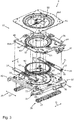
- the transverse oscillating device 21 is still characterized by a transversely to the commercial vehicle longitudinal extension 55 swingable cross slide member 56 whose vibrations are still through Damper 57 can be damped.
- This cross-slide part 56 is guided by the two spaced-apart transverse rail units 34 and 35 corresponding to the base support member 33.
- the commercial vehicle seat 1 still has a in the FIGS. 4 to 11 Locking device 60 shown in more detail, by means of which the cross-slide member 56 can be fixed directly to the base support member 33, a vibration function should not be desired.
- locking device 60 shown in more detail for fixing or releasing the transverse oscillating device 21 according to the invention has two locking units 61 and 62 spaced apart from each other in the longitudinal direction of the commercial vehicle 55, each having a locking element 65 or 66 mounted pivotably about a vertical pivot 63 and 64, respectively.
- locking elements 65 and 66 are designed as lever elements, as will be described in detail below.
- the two vertical pivot axes 63 and 64 are parallel to each other extending in a common vertical plane 67 (only exemplary in FIG. 4 Plotted) arranged.
- This vertical plane 67 is perpendicular to a horizontal plane 68, in which the two locking elements 65, 66 are pivotally mounted, said horizontal plane 68 according to the illustration in accordance with FIGS. 4, 5 . 10 and 11 coincides with the paper plane.
- horizontal plane is to be understood in the sense of the present invention such that this plane extends in the vehicle width direction and in the vehicle longitudinal direction 55 and only horizontally aligned when the utility vehicle is on a horizontal ground. Otherwise, this plane inclines with inclination of the entire commercial vehicle according to the Anlagenbreiten- and vehicle longitudinal direction. The same applies with regard to the vertical plane 67.
- the two locking elements 65 and 66 are arranged synchronously operable in the horizontal plane 68 between the two cross rail units 34 and 35 of the transverse oscillating device 21 exceptionally space-saving.
- the two locking elements 65 and 66 are each made of flat, about five millimeters thick or high basic body disks 70 (only exemplified, see FIGS. 4 and 5 ), so that they can easily accommodate between the two cross rail units 34 and 35.
- main body disks 70 of the two locking elements 65 and 66 are each configured arcuate, wherein at a first long side 71 (only exemplified, see FIG. 5 ) of the locking elements 65 and 66 each have a material recess 72 is provided, with which each of the locking elements 65 and 66 is snapped onto a corresponding locking pin member 73 and 74 of the locking device 60 when the locking device 60 and thus also the transverse oscillating device 21 in a locking position 75 (see FIG. 10 ) is located.
- each of the locking units 61 and 62 comprises a leg spring element 76 and 77, respectively.
- the second long side 78 can be referred to as an articulation side and the first long side 71 as a locking side of the respective locking element 65 or 66.
- a simple connection between the elastically deflectable and exclusively on Switzerland actuating forces transferable actuator 69 and the respective holder 79 of the locking element 65 and 66 is achieved here by the fact that the actuator 69 at its two ends in each case a cylinder barrel element 80, which in the corresponding holder 79 can be inserted.
- the elastically deflectable and transferable exclusively to train actuating forces actuator 69 is structurally advantageous realized by a single cable pull element 81.
- this cable pull element 81 is guided by means of a deflection device 82 from the first of the locking elements 65 to the second one of the locking elements 66 or vice versa.
- the deflecting device 82 in this case has only a guide die part 83 and a deflecting element 84 of the actuating handle 38, so that it is advantageously easy to build.
- the deflecting element 84 is in this case suspended by means of a coil spring 85 on the guide die part 83, so that the cable pull element 81 is always held in tension and thus biased in cooperation of the coil spring 85 and the two leg spring elements 76 and 77.
- the deflecting element 84 is in this case fixed to a rod element 86, wherein the rod element 86 in turn is mounted eccentrically on the actuating handle 38, so that the rod element 86 within the horizontal plane 68 and in or against the clamping direction 87 (see example FIG. 5 ) can be moved when the operating handle 38 is rotated in accordance with a further vertical axis 88.
- Guiding die part 83 shown in more detail is distinguished by two guideways 96 and 97 facing each other with respect to a division axis 95, each having an inlet region 98 or 99 facing the locking elements 65 and 66, wherein the two inlet regions 98 and 99 lie directly opposite one another.
- the guide die part 83 has two further guideways 100 and 101, which with their inlet regions 102 and 103 directly opposite the deflecting element 84 of the actuating handle 38.
- the other inlet regions 102 and 103 are arranged in the horizontal plane 68 by 90 ° with respect to the inlet regions 98 and 99 twisted, so that the single cable pull element 81 by means of two Umlenkrundungen 104 and 105 and the additional deflecting element 84 according to the FIG. 7 shown Seilzugverlauf 106 between the two locking elements 65, 66 and the operating handle 38 is guided continuously and without interruption.
- the locking elements 65, 66 are particularly space-saving between the two cross rail units 34 and 35 of the transverse oscillating device 21 on the cross slide member 56 arranged such that their respective height extent 107 in a spaced from one another by the bottom sides 108 and 109 of the cross rail units 34 and 35 spanned lower fictitious horizontal plane (not shown here) and by one of the upper sides 110 and 111 of the spaced-apart transverse rail units 34 and 35 spanned upper fictitious horizontal plane (also not shown here) limited space 112 are arranged.
- the structure of the seat base 7 in particular with respect to the x-axis can also be formed mirror image, that is:
- the actuating console 32 and in particular the manually operable gripping member 31 and the manually operable operating handle 38 may be arranged instead on the left side of the commercial vehicle seat on the right side of the commercial vehicle.
Landscapes
- Engineering & Computer Science (AREA)
- Aviation & Aerospace Engineering (AREA)
- Transportation (AREA)
- Mechanical Engineering (AREA)
- Seats For Vehicles (AREA)
Claims (11)
- Siège de véhicule utilitaire (1) ayant une partie siège (2), ayant une partie dossier (3) et ayant une sous-structure de siège (7) pour la disposition sur une partie carrosserie (8) d'un véhicule utilitaire, dans lequel la sous-structure de siège (7) comporte un dispositif d'oscillation transversale avec une partie coulisseau transversal (56) oscillant transversalement à l'étendue longitudinale (55) du véhicule utilitaire, au moyen de laquelle au moins la partie siège (2) est montée sur une partie support de base (33) de la sous-structure de siège (7) en étant apte à osciller transversalement à la direction de déplacement (5), et un dispositif de verrouillage (60) pour la fixation de la partie coulisseau transversal (56) sur la partie support de base (33), le dispositif de verrouillage (60) présentant deux unités de verrouillage (61, 62) disposées à distance l'une de l'autre dans l'étendue longitudinale (55) du véhicule utilitaire, ayant respectivement un élément de verrouillage (65, 66),
caractérisé par le fait que
chacun des éléments de verrouillage (65, 66) est monté pivotant autour d'un axe de pivotement vertical (63, 64), lesquels éléments de verrouillage sont disposés entre deux unités de rail transversal (34, 35) du dispositif d'oscillation transversale (21) dans un plan horizontal (68) actionnables de façon synchrone. - Siège de véhicule utilitaire (1) selon la revendication 1,
caractérisé par le fait que
chacun des éléments de verrouillage (65, 66) est disposé sur la partie coulisseau transversal (56), articulable par un élément d'actionnement (69) apte à être dévié élastiquement et apte à transmettre des forces d'actionnement exclusivement en traction. - Siège de véhicule utilitaire (1) selon l'une des revendications 1 ou 2,
caractérisé par le fait que
les deux éléments de verrouillage (65, 66) sont reliés fonctionnellement l'un à l'autre par un élément câble (81) continu unique dévié autour d'un élément déflecteur (84) d'une poignée d'actionnement (38) actionnable manuellement. - Siège de véhicule utilitaire (1) selon l'une des revendications 1 à 3,
caractérisé par le fait que
les éléments de verrouillage (65, 66), un élément d'actionnement (69) apte à être dévié élastiquement apte à être relié fonctionnellement à ces éléments de verrouillage (65, 66), des éléments déflecteurs (83, 84) d'un dispositif déflecteur (82) et une poignée d'actionnement (38) actionnable manuellement sont disposés dans un plan horizontal commun (68). - Siège de véhicule utilitaire (1) selon l'une des revendications 1 à 4,
caractérisé par le fait que
les éléments de verrouillage (65, 66) sont disposés sur la partie coulisseau transversal (56) entre deux unités de rail transversal (34, 35) du dispositif d'oscillation transversale de telle sorte que leur étendue en hauteur (107) est disposée dans un espace de construction (112) limité par un plan horizontal fictif inférieur s'étendant à partir des côtés inférieurs (108, 109) des unités de rail transversal (34, 35) disposées à distance l'une de l'autre et par un plan horizontal fictif supérieur s'étendant à partir des côtés supérieurs (110, 111) des unités de rail transversal (34, 35) disposées à distance l'une de l'autre. - Siège de véhicule utilitaire (1) selon l'une des revendications 1 à 5,
caractérisé par le fait que
un élément d'actionnement (69) apte à être dévié élastiquement et apte à transmettre des forces d'actionnement exclusivement en traction est disposé précontraint par un ressort, en particulier cet élément d'actionnement (69) apte à transmettre des forces d'actionnement en traction étant disposé précontraint par un élément déflecteur (84), précontraint par un ressort, d'une poignée d'actionnement (38) actionnable manuellement. - Siège de véhicule utilitaire (1) selon l'une des revendications 1 à 6,
caractérisé par le fait que
les axes de pivotement vertical (63, 64) des deux éléments de verrouillage (65, 66) sont disposés conjointement dans un plan vertical (67) s'étendant dans la direction longitudinale (55) du véhicule. - Siège de véhicule utilitaire (1) selon l'une des revendications 1 à 7,
caractérisé par le fait que
chacun des éléments de verrouillage (65, 66) est disposé agissant dans la direction d'une position de verrouillage (75) sur la partie coulisseau transversal (56), précontraint par un ressort. - Siège de véhicule utilitaire (1) selon l'une des revendications 1 à 8,
caractérisé par le fait que
les éléments de verrouillage (65, 66) présentent chacun un corps principal plat (70), sur lequel un évidement de matière (72) est prévu pour l'encliquetage sur un élément boulon de verrouillage (73, 74) du dispositif de verrouillage (60), l'évidement de matière (72) étant disposé sur un côté long (71) du corps principal (70), lequel côté long fait face à un côté d'articulation (78) du corps principal (70) défini par l'élément d'actionnement (69). - Siège de véhicule utilitaire (1) selon l'une des revendications 1 à 9,
caractérisé par le fait que
chacune des unités de verrouillage (61, 62) est associée à un élément boulon de verrouillage (65, 66), lequel est disposé sur la partie support de base (33). - Siège de véhicule utilitaire (1) ayant une partie siège (2), ayant une partie dossier (3) et ayant une sous-structure de siège (7) pour la disposition sur une partie carrosserie (8) d'un véhicule utilitaire, dans lequel la sous-structure de siège (7) comporte un dispositif d'oscillation transversale (21) ayant une partie coulisseau transversal (56) oscillant transversalement à l'étendue longitudinale (55) du véhicule utilitaire, au moyen de laquelle au moins la partie siège (2) est montée sur une partie support de base (33) de la sous-structure de siège (7) en étant apte à osciller transversalement par rapport à la direction de déplacement (5), et un dispositif de verrouillage (60) pour la fixation de la partie coulisseau transversal (56) sur la partie support de base (33), le dispositif de verrouillage (60) présentant deux unités de verrouillage (61, 62) disposées à distance l'une de l'autre dans l'étendue longitudinale (55) du véhicule utilitaire, ayant un élément de verrouillage respectif (65, 66),
caractérisé par le fait que
chaque élément de verrouillage (65, 66) est monté déplaçable le long d'un axe linéaire, lesquels éléments de verrouillage sont disposés entre deux unités de rail transversal (34, 35) du dispositif d'oscillation transversale (21) dans un plan horizontal (68), actionnables de façon synchrone.
Applications Claiming Priority (1)
| Application Number | Priority Date | Filing Date | Title |
|---|---|---|---|
| DE102012112525.2A DE102012112525B4 (de) | 2012-12-18 | 2012-12-18 | Nutzfahrzeugsitz mit doppelarretierbarem Querschlittenteil |
Publications (3)
| Publication Number | Publication Date |
|---|---|
| EP2746103A2 EP2746103A2 (fr) | 2014-06-25 |
| EP2746103A3 EP2746103A3 (fr) | 2015-07-22 |
| EP2746103B1 true EP2746103B1 (fr) | 2017-06-14 |
Family
ID=49766967
Family Applications (1)
| Application Number | Title | Priority Date | Filing Date |
|---|---|---|---|
| EP13197277.0A Active EP2746103B1 (fr) | 2012-12-18 | 2013-12-13 | Siège de véhicule utilitaire doté d'une partie de coulisseau transversal à double blocage |
Country Status (4)
| Country | Link |
|---|---|
| US (1) | US9085245B2 (fr) |
| EP (1) | EP2746103B1 (fr) |
| CN (1) | CN103863146A (fr) |
| DE (1) | DE102012112525B4 (fr) |
Families Citing this family (21)
| Publication number | Priority date | Publication date | Assignee | Title |
|---|---|---|---|---|
| DE102012112138B3 (de) | 2012-12-12 | 2014-05-15 | Grammer Ag | Fahrzeugsitz |
| DE102012112523B4 (de) | 2012-12-18 | 2020-11-12 | Grammer Aktiengesellschaft | Nutzfahrzeugsitz mit drehbarem Sitzteil |
| DE102012112528B4 (de) | 2012-12-18 | 2014-09-18 | Grammer Ag | Nutzfahrzeugsitz mit einer Drehverstelleinrichtung-Überlastsicherungseinheit |
| DE102012112527B3 (de) | 2012-12-18 | 2014-06-05 | Grammer Ag | Nutzfahrzeugsitz mit integrierter Drehverstelleinrichtung |
| DE102014107816B4 (de) * | 2014-06-03 | 2018-05-03 | Grammer Aktiengesellschaft | Nutzfahrzeugsitz mit arretierbarem Querschlittenteil |
| DE102014109191B8 (de) | 2014-07-01 | 2018-12-20 | Grammer Aktiengesellschaft | Federungssystem für Fahrzeugsitze und Verfahren zum Federn von Fahrzeugsitzteilen |
| DE102015113176B4 (de) | 2015-08-10 | 2021-12-30 | Grammer Aktiengesellschaft | Horizontalschwingungsvorrichtung für einen Fahrzeugsitz |
| CN207725260U (zh) * | 2017-11-28 | 2018-08-14 | 延锋安道拓座椅有限公司 | 一种锁止装置 |
| US11407336B2 (en) * | 2018-06-05 | 2022-08-09 | Schaeffler Technologies AG & Co. KG | Stamped splined locking mechanism for rotating automotive seat bracket |
| US10800298B2 (en) * | 2018-08-28 | 2020-10-13 | Deere & Company | Seat suspension system with horizontal movement and dampening |
| CN109823239B (zh) * | 2019-02-14 | 2023-03-10 | 延锋国际座椅系统有限公司 | 汽车座椅电动旋转装置 |
| CN109878383B (zh) * | 2019-04-08 | 2024-02-09 | 浙江工业职业技术学院 | 一种无人驾驶汽车的调节座椅 |
| US11772520B2 (en) | 2020-11-09 | 2023-10-03 | Ford Global Technologies, Llc | Remote notification and adjustment of a passenger compartment arrangement |
| US12077068B2 (en) | 2020-11-09 | 2024-09-03 | Ford Global Technologies, Llc | Authorization-based adjustment of passenger compartment arrangement |
| US11904732B2 (en) | 2020-11-09 | 2024-02-20 | Ford Global Technologies, Llc | Vehicular system capable of adjusting a passenger compartment from a first arrangement to a child care arrangement |
| US11772519B2 (en) | 2020-11-09 | 2023-10-03 | Ford Global Technologies, Llc | Vehicular system capable of adjusting a passenger compartment from a first arrangement to a child seat arrangement |
| US11772517B2 (en) | 2020-11-09 | 2023-10-03 | Ford Global Technologies, Llc | Vehicular system capable of adjusting a passenger compartment from a child seat arrangement to a second arrangement |
| US11731535B2 (en) | 2020-11-09 | 2023-08-22 | Ford Global Technologies, Llc | Vehicular system capable of adjusting a passenger compartment from a child care arrangement to a second arrangement |
| US12257932B2 (en) | 2020-11-09 | 2025-03-25 | Ford Global Technologies, Llc | Exterior imager utilized in adjusting a passenger compartment arrangement |
| CN117957138A (zh) | 2021-07-29 | 2024-04-30 | 丰田自动车工程及制造北美公司 | 具有固定框架和可移动座垫的座椅组件 |
| KR20230082382A (ko) * | 2021-12-01 | 2023-06-08 | 주식회사 포스코 | 시트프레임 |
Family Cites Families (33)
| Publication number | Priority date | Publication date | Assignee | Title |
|---|---|---|---|---|
| US3258241A (en) * | 1964-11-12 | 1966-06-28 | Bostrom Corp | Vehicle seat suspension |
| DE1630556A1 (de) * | 1967-11-10 | 1971-06-03 | Isringhausen Geb | Lagerung fuer Fahrzeugsitze |
| FR2060183A1 (fr) * | 1969-09-10 | 1971-06-18 | Peugeot & Renault | |
| IT7953821U1 (it) * | 1979-12-19 | 1981-06-19 | Gilardini Spa | Dispositivo di bloccaggio di una estremita' di una cintura di sicurezza per autoveicoli, rispetto ad una guida di scorrimento di un sedile. |
| US4344597A (en) * | 1980-04-21 | 1982-08-17 | Milsco Manufacturing Company | Vehicle seat with fore-and-aft shock isolation |
| JPS57167832A (en) * | 1981-04-10 | 1982-10-15 | Tenryu Kogyo Kk | Seat extension mechanism which can be easily operated |
| DE3218379A1 (de) * | 1982-05-15 | 1983-11-17 | Heinz 5650 Solingen Seitel | Fahrzeugsitz mit einer in fahrtrichtung verstellbaren und arretierbaren schienenfuehrung |
| JPS5914525A (ja) * | 1982-07-14 | 1984-01-25 | Nissan Motor Co Ltd | 回転座席における摺動ロツク機構 |
| US4834452A (en) * | 1988-07-05 | 1989-05-30 | Goodrich Grover G | Swivel seat and frame |
| US5076529A (en) * | 1991-01-29 | 1991-12-31 | Atwood Industries, Inc. | Seat adjuster with improved crash resistance |
| US5161765A (en) * | 1991-03-04 | 1992-11-10 | Aero Tech United Corporation | Moveable seat mounting device |
| FR2684609B1 (fr) * | 1991-12-10 | 1994-02-11 | Faure Automobile Bertrand | Base tournante a securite permettant la rotation de 180degre d'un siege dans un vehicule automobile ou analogue. |
| US5720462A (en) * | 1995-03-31 | 1998-02-24 | Sears Manufacturing Company | Rotatable and fore-aft slidable seat mount and controls |
| CN2250671Y (zh) * | 1995-08-29 | 1997-04-02 | 上海旭卡机械电器有限公司 | 凸轮锁式滑动和转动装置 |
| US6079786A (en) * | 1997-05-07 | 2000-06-27 | Brunswick Corporation | One-shot pedestal swivel seat lock/release mechanism |
| CN2369064Y (zh) * | 1999-04-08 | 2000-03-15 | 上海旭卡机械电器有限公司 | 可随动操作的滚动旋转座椅装置 |
| US6325456B1 (en) * | 2000-02-18 | 2001-12-04 | Garnett Carnahan | Chair with a sliding and swiveling device |
| IT1320729B1 (it) * | 2000-10-24 | 2003-12-10 | Fiat Auto Spa | Dispositivo di traslazione laterale per un sedile di autoveicolo. |
| US20030189370A1 (en) * | 2002-04-05 | 2003-10-09 | Hemmer Nathan A. | Adjustable chair for vehicles |
| US7350870B2 (en) * | 2003-12-12 | 2008-04-01 | Capro, Ltd. | Integrated compensator module |
| US7044553B2 (en) * | 2004-06-22 | 2006-05-16 | Sears Manufacturing Co. | Vehicle seat suspension with omni directional isolator |
| US7121608B2 (en) * | 2004-09-23 | 2006-10-17 | Crown Equipment Corporation | Rotating and/or swiveling seat |
| US7520567B2 (en) * | 2004-09-23 | 2009-04-21 | Crown Equipment Corporation | Systems and methods for seat repositioning |
| US7219961B2 (en) * | 2005-04-06 | 2007-05-22 | Cnh America Llc | Pivoting seat |
| WO2007094707A1 (fr) * | 2006-02-13 | 2007-08-23 | Volvo Construction Equipment Ab | Dispositif de fixation de siege de vehicule |
| US8033589B2 (en) * | 2006-08-01 | 2011-10-11 | Toyota Shatai Kabushiki Kaisha | Vehicle seat |
| US7845703B2 (en) * | 2007-02-06 | 2010-12-07 | Freedom Sciences, Llc | Seating systems for motor vehicles |
| DE102008022419A1 (de) * | 2008-05-07 | 2009-11-12 | GM Global Technology Operations, Inc., Detroit | Antriebseinrichtung für Kraftfahrzeugschwenksitz |
| JP4505028B2 (ja) * | 2008-06-09 | 2010-07-14 | トヨタ自動車株式会社 | シート |
| US8800976B2 (en) * | 2011-01-21 | 2014-08-12 | Cvg Management Corporation | Fore-aft vibration isolator |
| DE102011013122B4 (de) * | 2011-03-04 | 2017-12-14 | Grammer Aktiengesellschaft | Hebelmechanismus für Dämpferverstellung für Horizontalfederung |
| DE102011103225B4 (de) * | 2011-06-01 | 2013-04-25 | Keiper Gmbh & Co. Kg | Fahrzeugsitz |
| US8857763B2 (en) * | 2012-01-27 | 2014-10-14 | Bell Helicopter Textron Inc. | Vehicle crewstation seat assembly |
-
2012
- 2012-12-18 DE DE102012112525.2A patent/DE102012112525B4/de not_active Expired - Fee Related
-
2013
- 2013-12-13 EP EP13197277.0A patent/EP2746103B1/fr active Active
- 2013-12-17 US US14/109,226 patent/US9085245B2/en active Active
- 2013-12-18 CN CN201310702974.XA patent/CN103863146A/zh active Pending
Non-Patent Citations (1)
| Title |
|---|
| None * |
Also Published As
| Publication number | Publication date |
|---|---|
| DE102012112525B4 (de) | 2017-12-28 |
| US9085245B2 (en) | 2015-07-21 |
| EP2746103A3 (fr) | 2015-07-22 |
| EP2746103A2 (fr) | 2014-06-25 |
| DE102012112525A1 (de) | 2014-06-18 |
| US20140167468A1 (en) | 2014-06-19 |
| CN103863146A (zh) | 2014-06-18 |
Similar Documents
| Publication | Publication Date | Title |
|---|---|---|
| EP2746103B1 (fr) | Siège de véhicule utilitaire doté d'une partie de coulisseau transversal à double blocage | |
| DE102014107816B4 (de) | Nutzfahrzeugsitz mit arretierbarem Querschlittenteil | |
| EP1492702B1 (fr) | Appui-tete pour siege | |
| EP0022933B1 (fr) | Chaise avec siège inclinable et dossier inclinable | |
| DE60304991T2 (de) | Kopfstütze für kraftfahrzeuge | |
| DE2813534C2 (de) | Verstellbarer Fahrzeugsitz, insbesondere Kraftfahrzeugsitz | |
| EP0111165B1 (fr) | Châssis de siège ayant un compensateur de pente pour véhicules, notamment tracteurs agricoles | |
| DE3139945A1 (de) | Sitz, insbesondere kraftfahrzeugsitz | |
| EP3552874B1 (fr) | Siège de véhicule pourvu de console de changement de vitesses réglable | |
| WO2011006592A1 (fr) | Siège pivotant pour véhicule | |
| DE102018009665B3 (de) | Fahrzeugsitz mit einer Einstellvorrichtung und Fahrzeug mit einem solchen Fahrzeugsitz | |
| DE102018109611B4 (de) | Kopfstütze | |
| EP3590760B1 (fr) | Appuie-tête | |
| DE3129063C2 (de) | Kopfstütze für Fahrzeugsitze | |
| DE102014107814B4 (de) | Nutzfahrzeugsitz | |
| DE10236259B4 (de) | Kopfstütze für Fahrzeugsitze | |
| EP3819164B1 (fr) | Dispositif d'équipement du véhicule | |
| DE3531992C2 (de) | Verstelleinrichtung für eine in ihrer Neigung verstellbare Kraftfahrzeug-Hintersitzlehne | |
| WO2014118034A1 (fr) | Dispositif de réglage de l'inclinaison d'un siège de véhicule et siège de véhicule | |
| DE69700609T2 (de) | Einstellbare Rücklehne für Fahrzeugsitz | |
| WO2006079300A2 (fr) | Unite de dossier pour siege d'automobile | |
| DE102010042881B4 (de) | Fahrzeugsitz mit einer Sitztiefenverstelleinrichtung | |
| EP1604863B1 (fr) | Dispositif pour maintenir le dossier d'un siège de véhicule automobile | |
| DE10318718A1 (de) | Verstellbarer Kraftfahrzeugsitz, insbesondere für die zweite und dritte Sitzreihe | |
| DE4310454C1 (de) | Armlehne für Fahrzeugsitze |
Legal Events
| Date | Code | Title | Description |
|---|---|---|---|
| PUAI | Public reference made under article 153(3) epc to a published international application that has entered the european phase |
Free format text: ORIGINAL CODE: 0009012 |
|
| 17P | Request for examination filed |
Effective date: 20131213 |
|
| AK | Designated contracting states |
Kind code of ref document: A2 Designated state(s): AL AT BE BG CH CY CZ DE DK EE ES FI FR GB GR HR HU IE IS IT LI LT LU LV MC MK MT NL NO PL PT RO RS SE SI SK SM TR |
|
| AX | Request for extension of the european patent |
Extension state: BA ME |
|
| PUAL | Search report despatched |
Free format text: ORIGINAL CODE: 0009013 |
|
| AK | Designated contracting states |
Kind code of ref document: A3 Designated state(s): AL AT BE BG CH CY CZ DE DK EE ES FI FR GB GR HR HU IE IS IT LI LT LU LV MC MK MT NL NO PL PT RO RS SE SI SK SM TR |
|
| AX | Request for extension of the european patent |
Extension state: BA ME |
|
| RIC1 | Information provided on ipc code assigned before grant |
Ipc: B60N 2/44 20060101ALI20150618BHEP Ipc: B60N 2/50 20060101AFI20150618BHEP Ipc: B60N 2/14 20060101ALI20150618BHEP Ipc: B60N 2/08 20060101ALI20150618BHEP Ipc: B60N 2/06 20060101ALI20150618BHEP |
|
| R17P | Request for examination filed (corrected) |
Effective date: 20151207 |
|
| RBV | Designated contracting states (corrected) |
Designated state(s): AL AT BE BG CH CY CZ DE DK EE ES FI FR GB GR HR HU IE IS IT LI LT LU LV MC MK MT NL NO PL PT RO RS SE SI SK SM TR |
|
| REG | Reference to a national code |
Ref country code: DE Ref legal event code: R079 Ref document number: 502013007487 Country of ref document: DE Free format text: PREVIOUS MAIN CLASS: B60N0002500000 Ipc: B60N0002015000 |
|
| GRAP | Despatch of communication of intention to grant a patent |
Free format text: ORIGINAL CODE: EPIDOSNIGR1 |
|
| RIC1 | Information provided on ipc code assigned before grant |
Ipc: B60N 2/015 20060101AFI20170303BHEP Ipc: B60N 2/08 20060101ALI20170303BHEP Ipc: B60N 2/14 20060101ALI20170303BHEP Ipc: B60N 2/44 20060101ALI20170303BHEP Ipc: B60N 2/06 20060101ALI20170303BHEP Ipc: B60N 2/50 20060101ALI20170303BHEP |
|
| INTG | Intention to grant announced |
Effective date: 20170328 |
|
| GRAS | Grant fee paid |
Free format text: ORIGINAL CODE: EPIDOSNIGR3 |
|
| GRAA | (expected) grant |
Free format text: ORIGINAL CODE: 0009210 |
|
| AK | Designated contracting states |
Kind code of ref document: B1 Designated state(s): AL AT BE BG CH CY CZ DE DK EE ES FI FR GB GR HR HU IE IS IT LI LT LU LV MC MK MT NL NO PL PT RO RS SE SI SK SM TR |
|
| REG | Reference to a national code |
Ref country code: GB Ref legal event code: FG4D Free format text: NOT ENGLISH |
|
| REG | Reference to a national code |
Ref country code: CH Ref legal event code: EP Ref country code: AT Ref legal event code: REF Ref document number: 900616 Country of ref document: AT Kind code of ref document: T Effective date: 20170615 |
|
| REG | Reference to a national code |
Ref country code: IE Ref legal event code: FG4D Free format text: LANGUAGE OF EP DOCUMENT: GERMAN |
|
| REG | Reference to a national code |
Ref country code: DE Ref legal event code: R096 Ref document number: 502013007487 Country of ref document: DE |
|
| REG | Reference to a national code |
Ref country code: NL Ref legal event code: MP Effective date: 20170614 |
|
| REG | Reference to a national code |
Ref country code: LT Ref legal event code: MG4D |
|
| PG25 | Lapsed in a contracting state [announced via postgrant information from national office to epo] |
Ref country code: LT Free format text: LAPSE BECAUSE OF FAILURE TO SUBMIT A TRANSLATION OF THE DESCRIPTION OR TO PAY THE FEE WITHIN THE PRESCRIBED TIME-LIMIT Effective date: 20170614 Ref country code: FI Free format text: LAPSE BECAUSE OF FAILURE TO SUBMIT A TRANSLATION OF THE DESCRIPTION OR TO PAY THE FEE WITHIN THE PRESCRIBED TIME-LIMIT Effective date: 20170614 Ref country code: HR Free format text: LAPSE BECAUSE OF FAILURE TO SUBMIT A TRANSLATION OF THE DESCRIPTION OR TO PAY THE FEE WITHIN THE PRESCRIBED TIME-LIMIT Effective date: 20170614 Ref country code: GR Free format text: LAPSE BECAUSE OF FAILURE TO SUBMIT A TRANSLATION OF THE DESCRIPTION OR TO PAY THE FEE WITHIN THE PRESCRIBED TIME-LIMIT Effective date: 20170915 Ref country code: NO Free format text: LAPSE BECAUSE OF FAILURE TO SUBMIT A TRANSLATION OF THE DESCRIPTION OR TO PAY THE FEE WITHIN THE PRESCRIBED TIME-LIMIT Effective date: 20170914 |
|
| PG25 | Lapsed in a contracting state [announced via postgrant information from national office to epo] |
Ref country code: NL Free format text: LAPSE BECAUSE OF FAILURE TO SUBMIT A TRANSLATION OF THE DESCRIPTION OR TO PAY THE FEE WITHIN THE PRESCRIBED TIME-LIMIT Effective date: 20170614 Ref country code: RS Free format text: LAPSE BECAUSE OF FAILURE TO SUBMIT A TRANSLATION OF THE DESCRIPTION OR TO PAY THE FEE WITHIN THE PRESCRIBED TIME-LIMIT Effective date: 20170614 Ref country code: LV Free format text: LAPSE BECAUSE OF FAILURE TO SUBMIT A TRANSLATION OF THE DESCRIPTION OR TO PAY THE FEE WITHIN THE PRESCRIBED TIME-LIMIT Effective date: 20170614 Ref country code: BG Free format text: LAPSE BECAUSE OF FAILURE TO SUBMIT A TRANSLATION OF THE DESCRIPTION OR TO PAY THE FEE WITHIN THE PRESCRIBED TIME-LIMIT Effective date: 20170914 Ref country code: SE Free format text: LAPSE BECAUSE OF FAILURE TO SUBMIT A TRANSLATION OF THE DESCRIPTION OR TO PAY THE FEE WITHIN THE PRESCRIBED TIME-LIMIT Effective date: 20170614 |
|
| REG | Reference to a national code |
Ref country code: FR Ref legal event code: PLFP Year of fee payment: 5 |
|
| PG25 | Lapsed in a contracting state [announced via postgrant information from national office to epo] |
Ref country code: RO Free format text: LAPSE BECAUSE OF FAILURE TO SUBMIT A TRANSLATION OF THE DESCRIPTION OR TO PAY THE FEE WITHIN THE PRESCRIBED TIME-LIMIT Effective date: 20170614 Ref country code: EE Free format text: LAPSE BECAUSE OF FAILURE TO SUBMIT A TRANSLATION OF THE DESCRIPTION OR TO PAY THE FEE WITHIN THE PRESCRIBED TIME-LIMIT Effective date: 20170614 Ref country code: CZ Free format text: LAPSE BECAUSE OF FAILURE TO SUBMIT A TRANSLATION OF THE DESCRIPTION OR TO PAY THE FEE WITHIN THE PRESCRIBED TIME-LIMIT Effective date: 20170614 Ref country code: SK Free format text: LAPSE BECAUSE OF FAILURE TO SUBMIT A TRANSLATION OF THE DESCRIPTION OR TO PAY THE FEE WITHIN THE PRESCRIBED TIME-LIMIT Effective date: 20170614 |
|
| PG25 | Lapsed in a contracting state [announced via postgrant information from national office to epo] |
Ref country code: IS Free format text: LAPSE BECAUSE OF FAILURE TO SUBMIT A TRANSLATION OF THE DESCRIPTION OR TO PAY THE FEE WITHIN THE PRESCRIBED TIME-LIMIT Effective date: 20171014 Ref country code: SM Free format text: LAPSE BECAUSE OF FAILURE TO SUBMIT A TRANSLATION OF THE DESCRIPTION OR TO PAY THE FEE WITHIN THE PRESCRIBED TIME-LIMIT Effective date: 20170614 Ref country code: PL Free format text: LAPSE BECAUSE OF FAILURE TO SUBMIT A TRANSLATION OF THE DESCRIPTION OR TO PAY THE FEE WITHIN THE PRESCRIBED TIME-LIMIT Effective date: 20170614 Ref country code: ES Free format text: LAPSE BECAUSE OF FAILURE TO SUBMIT A TRANSLATION OF THE DESCRIPTION OR TO PAY THE FEE WITHIN THE PRESCRIBED TIME-LIMIT Effective date: 20170614 |
|
| REG | Reference to a national code |
Ref country code: DE Ref legal event code: R097 Ref document number: 502013007487 Country of ref document: DE |
|
| PLBE | No opposition filed within time limit |
Free format text: ORIGINAL CODE: 0009261 |
|
| STAA | Information on the status of an ep patent application or granted ep patent |
Free format text: STATUS: NO OPPOSITION FILED WITHIN TIME LIMIT |
|
| PG25 | Lapsed in a contracting state [announced via postgrant information from national office to epo] |
Ref country code: DK Free format text: LAPSE BECAUSE OF FAILURE TO SUBMIT A TRANSLATION OF THE DESCRIPTION OR TO PAY THE FEE WITHIN THE PRESCRIBED TIME-LIMIT Effective date: 20170614 |
|
| 26N | No opposition filed |
Effective date: 20180315 |
|
| REG | Reference to a national code |
Ref country code: CH Ref legal event code: PL |
|
| GBPC | Gb: european patent ceased through non-payment of renewal fee |
Effective date: 20171213 |
|
| PG25 | Lapsed in a contracting state [announced via postgrant information from national office to epo] |
Ref country code: SI Free format text: LAPSE BECAUSE OF FAILURE TO SUBMIT A TRANSLATION OF THE DESCRIPTION OR TO PAY THE FEE WITHIN THE PRESCRIBED TIME-LIMIT Effective date: 20170614 |
|
| REG | Reference to a national code |
Ref country code: IE Ref legal event code: MM4A |
|
| PG25 | Lapsed in a contracting state [announced via postgrant information from national office to epo] |
Ref country code: MT Free format text: LAPSE BECAUSE OF FAILURE TO SUBMIT A TRANSLATION OF THE DESCRIPTION OR TO PAY THE FEE WITHIN THE PRESCRIBED TIME-LIMIT Effective date: 20170614 Ref country code: LU Free format text: LAPSE BECAUSE OF NON-PAYMENT OF DUE FEES Effective date: 20171213 |
|
| REG | Reference to a national code |
Ref country code: BE Ref legal event code: MM Effective date: 20171231 |
|
| PG25 | Lapsed in a contracting state [announced via postgrant information from national office to epo] |
Ref country code: IE Free format text: LAPSE BECAUSE OF NON-PAYMENT OF DUE FEES Effective date: 20171213 |
|
| PG25 | Lapsed in a contracting state [announced via postgrant information from national office to epo] |
Ref country code: LI Free format text: LAPSE BECAUSE OF NON-PAYMENT OF DUE FEES Effective date: 20171231 Ref country code: CH Free format text: LAPSE BECAUSE OF NON-PAYMENT OF DUE FEES Effective date: 20171231 Ref country code: GB Free format text: LAPSE BECAUSE OF NON-PAYMENT OF DUE FEES Effective date: 20171213 Ref country code: BE Free format text: LAPSE BECAUSE OF NON-PAYMENT OF DUE FEES Effective date: 20171231 |
|
| PG25 | Lapsed in a contracting state [announced via postgrant information from national office to epo] |
Ref country code: MC Free format text: LAPSE BECAUSE OF FAILURE TO SUBMIT A TRANSLATION OF THE DESCRIPTION OR TO PAY THE FEE WITHIN THE PRESCRIBED TIME-LIMIT Effective date: 20170614 Ref country code: HU Free format text: LAPSE BECAUSE OF FAILURE TO SUBMIT A TRANSLATION OF THE DESCRIPTION OR TO PAY THE FEE WITHIN THE PRESCRIBED TIME-LIMIT; INVALID AB INITIO Effective date: 20131213 |
|
| PG25 | Lapsed in a contracting state [announced via postgrant information from national office to epo] |
Ref country code: CY Free format text: LAPSE BECAUSE OF NON-PAYMENT OF DUE FEES Effective date: 20170614 |
|
| PG25 | Lapsed in a contracting state [announced via postgrant information from national office to epo] |
Ref country code: MK Free format text: LAPSE BECAUSE OF FAILURE TO SUBMIT A TRANSLATION OF THE DESCRIPTION OR TO PAY THE FEE WITHIN THE PRESCRIBED TIME-LIMIT Effective date: 20170614 |
|
| REG | Reference to a national code |
Ref country code: AT Ref legal event code: MM01 Ref document number: 900616 Country of ref document: AT Kind code of ref document: T Effective date: 20181213 |
|
| PG25 | Lapsed in a contracting state [announced via postgrant information from national office to epo] |
Ref country code: TR Free format text: LAPSE BECAUSE OF FAILURE TO SUBMIT A TRANSLATION OF THE DESCRIPTION OR TO PAY THE FEE WITHIN THE PRESCRIBED TIME-LIMIT Effective date: 20170614 |
|
| PG25 | Lapsed in a contracting state [announced via postgrant information from national office to epo] |
Ref country code: AT Free format text: LAPSE BECAUSE OF NON-PAYMENT OF DUE FEES Effective date: 20181213 |
|
| PG25 | Lapsed in a contracting state [announced via postgrant information from national office to epo] |
Ref country code: PT Free format text: LAPSE BECAUSE OF FAILURE TO SUBMIT A TRANSLATION OF THE DESCRIPTION OR TO PAY THE FEE WITHIN THE PRESCRIBED TIME-LIMIT Effective date: 20170614 |
|
| PG25 | Lapsed in a contracting state [announced via postgrant information from national office to epo] |
Ref country code: AL Free format text: LAPSE BECAUSE OF FAILURE TO SUBMIT A TRANSLATION OF THE DESCRIPTION OR TO PAY THE FEE WITHIN THE PRESCRIBED TIME-LIMIT Effective date: 20170614 |
|
| P01 | Opt-out of the competence of the unified patent court (upc) registered |
Effective date: 20230522 |
|
| PGFP | Annual fee paid to national office [announced via postgrant information from national office to epo] |
Ref country code: FR Payment date: 20251217 Year of fee payment: 13 |
|
| PGFP | Annual fee paid to national office [announced via postgrant information from national office to epo] |
Ref country code: DE Payment date: 20251222 Year of fee payment: 13 |
|
| PGFP | Annual fee paid to national office [announced via postgrant information from national office to epo] |
Ref country code: IT Payment date: 20251231 Year of fee payment: 13 |