EP2746204A2 - Vorrichtung und Verfahren zum Drehen von flachen Gütern - Google Patents
Vorrichtung und Verfahren zum Drehen von flachen Gütern Download PDFInfo
- Publication number
- EP2746204A2 EP2746204A2 EP13195686.4A EP13195686A EP2746204A2 EP 2746204 A2 EP2746204 A2 EP 2746204A2 EP 13195686 A EP13195686 A EP 13195686A EP 2746204 A2 EP2746204 A2 EP 2746204A2
- Authority
- EP
- European Patent Office
- Prior art keywords
- rotating means
- rotating
- rotation
- engagement
- rotary
- Prior art date
- Legal status (The legal status is an assumption and is not a legal conclusion. Google has not performed a legal analysis and makes no representation as to the accuracy of the status listed.)
- Granted
Links
Images


Classifications
-
- B—PERFORMING OPERATIONS; TRANSPORTING
- B65—CONVEYING; PACKING; STORING; HANDLING THIN OR FILAMENTARY MATERIAL
- B65G—TRANSPORT OR STORAGE DEVICES, e.g. CONVEYORS FOR LOADING OR TIPPING, SHOP CONVEYOR SYSTEMS OR PNEUMATIC TUBE CONVEYORS
- B65G47/00—Article or material-handling devices associated with conveyors; Methods employing such devices
- B65G47/22—Devices influencing the relative position or the attitude of articles during transit by conveyors
- B65G47/24—Devices influencing the relative position or the attitude of articles during transit by conveyors orientating the articles
- B65G47/244—Devices influencing the relative position or the attitude of articles during transit by conveyors orientating the articles by turning them about an axis substantially perpendicular to the conveying plane
- B65G47/2445—Devices influencing the relative position or the attitude of articles during transit by conveyors orientating the articles by turning them about an axis substantially perpendicular to the conveying plane by means of at least two co-operating endless conveying elements
-
- B—PERFORMING OPERATIONS; TRANSPORTING
- B65—CONVEYING; PACKING; STORING; HANDLING THIN OR FILAMENTARY MATERIAL
- B65H—HANDLING THIN OR FILAMENTARY MATERIAL, e.g. SHEETS, WEBS, CABLES
- B65H5/00—Feeding articles separated from piles; Feeding articles to machines
- B65H5/06—Feeding articles separated from piles; Feeding articles to machines by rollers or balls, e.g. between rollers
- B65H5/062—Feeding articles separated from piles; Feeding articles to machines by rollers or balls, e.g. between rollers between rollers or balls
-
- B—PERFORMING OPERATIONS; TRANSPORTING
- B65—CONVEYING; PACKING; STORING; HANDLING THIN OR FILAMENTARY MATERIAL
- B65H—HANDLING THIN OR FILAMENTARY MATERIAL, e.g. SHEETS, WEBS, CABLES
- B65H7/00—Controlling article feeding, separating, pile-advancing, or associated apparatus, to take account of incorrect feeding, absence of articles, or presence of faulty articles
- B65H7/02—Controlling article feeding, separating, pile-advancing, or associated apparatus, to take account of incorrect feeding, absence of articles, or presence of faulty articles by feelers or detectors
- B65H7/06—Controlling article feeding, separating, pile-advancing, or associated apparatus, to take account of incorrect feeding, absence of articles, or presence of faulty articles by feelers or detectors responsive to presence of faulty articles or incorrect separation or feed
- B65H7/08—Controlling article feeding, separating, pile-advancing, or associated apparatus, to take account of incorrect feeding, absence of articles, or presence of faulty articles by feelers or detectors responsive to presence of faulty articles or incorrect separation or feed responsive to incorrect front register
-
- B—PERFORMING OPERATIONS; TRANSPORTING
- B65—CONVEYING; PACKING; STORING; HANDLING THIN OR FILAMENTARY MATERIAL
- B65H—HANDLING THIN OR FILAMENTARY MATERIAL, e.g. SHEETS, WEBS, CABLES
- B65H9/00—Registering, e.g. orientating, articles; Devices therefor
- B65H9/002—Registering, e.g. orientating, articles; Devices therefor changing orientation of sheet by only controlling movement of the forwarding means, i.e. without the use of stop or register wall
-
- B—PERFORMING OPERATIONS; TRANSPORTING
- B65—CONVEYING; PACKING; STORING; HANDLING THIN OR FILAMENTARY MATERIAL
- B65H—HANDLING THIN OR FILAMENTARY MATERIAL, e.g. SHEETS, WEBS, CABLES
- B65H2301/00—Handling processes for sheets or webs
- B65H2301/30—Orientation, displacement, position of the handled material
- B65H2301/33—Modifying, selecting, changing orientation
- B65H2301/332—Turning, overturning
- B65H2301/3321—Turning, overturning kinetic therefor
- B65H2301/33216—Turning, overturning kinetic therefor about an axis perpendicular to the direction of displacement and to the surface of material
-
- B—PERFORMING OPERATIONS; TRANSPORTING
- B65—CONVEYING; PACKING; STORING; HANDLING THIN OR FILAMENTARY MATERIAL
- B65H—HANDLING THIN OR FILAMENTARY MATERIAL, e.g. SHEETS, WEBS, CABLES
- B65H2301/00—Handling processes for sheets or webs
- B65H2301/30—Orientation, displacement, position of the handled material
- B65H2301/33—Modifying, selecting, changing orientation
- B65H2301/332—Turning, overturning
- B65H2301/3322—Turning, overturning according to a determined angle
- B65H2301/33222—90°
-
- B—PERFORMING OPERATIONS; TRANSPORTING
- B65—CONVEYING; PACKING; STORING; HANDLING THIN OR FILAMENTARY MATERIAL
- B65H—HANDLING THIN OR FILAMENTARY MATERIAL, e.g. SHEETS, WEBS, CABLES
- B65H2301/00—Handling processes for sheets or webs
- B65H2301/30—Orientation, displacement, position of the handled material
- B65H2301/34—Modifying, selecting, changing direction of displacement
- B65H2301/341—Modifying, selecting, changing direction of displacement without change of plane of displacement
- B65H2301/3411—Right angle arrangement, i.e. 90 degrees
- B65H2301/34112—Right angle arrangement, i.e. 90 degrees changing leading edge
-
- B—PERFORMING OPERATIONS; TRANSPORTING
- B65—CONVEYING; PACKING; STORING; HANDLING THIN OR FILAMENTARY MATERIAL
- B65H—HANDLING THIN OR FILAMENTARY MATERIAL, e.g. SHEETS, WEBS, CABLES
- B65H2404/00—Parts for transporting or guiding the handled material
- B65H2404/10—Rollers
- B65H2404/14—Roller pairs
- B65H2404/144—Roller pairs with relative movement of the rollers to / from each other
-
- B—PERFORMING OPERATIONS; TRANSPORTING
- B65—CONVEYING; PACKING; STORING; HANDLING THIN OR FILAMENTARY MATERIAL
- B65H—HANDLING THIN OR FILAMENTARY MATERIAL, e.g. SHEETS, WEBS, CABLES
- B65H2511/00—Dimensions; Position; Numbers; Identification; Occurrences
- B65H2511/20—Location in space
- B65H2511/21—Angle
- B65H2511/216—Orientation, e.g. with respect to direction of movement
-
- B—PERFORMING OPERATIONS; TRANSPORTING
- B65—CONVEYING; PACKING; STORING; HANDLING THIN OR FILAMENTARY MATERIAL
- B65H—HANDLING THIN OR FILAMENTARY MATERIAL, e.g. SHEETS, WEBS, CABLES
- B65H2513/00—Dynamic entities; Timing aspects
- B65H2513/10—Speed
- B65H2513/11—Speed angular
-
- B—PERFORMING OPERATIONS; TRANSPORTING
- B65—CONVEYING; PACKING; STORING; HANDLING THIN OR FILAMENTARY MATERIAL
- B65H—HANDLING THIN OR FILAMENTARY MATERIAL, e.g. SHEETS, WEBS, CABLES
- B65H2513/00—Dynamic entities; Timing aspects
- B65H2513/50—Timing
- B65H2513/52—Age; Duration; Life time or chronology of event
Definitions
- the invention relates to a device for rotating flat goods moving in a transport direction according to the preamble of claim 1 and to a corresponding method according to the preamble of claim 2.
- Devices of the generic type are used for example in paper processing machines, such. As inserters, printers or copiers used.
- the material to be turned may be, for example, individual sheets or sheets or a sheet stack of at least two sheets.
- generic devices can also be used for turning other flat goods, such. For example, for turning plastic films, cardboard sheets or the like or for turning of connected or stapled sheets in the form of catalogs, brochures, booklets or similar products.
- a device for rotating rectangular cardboard sheets by 90 ° is known, which are stored in a predetermined orientation for further processing in a container.
- This known device comprises a conveyor belt which is moved at a first speed in a transport direction in order to move the cardboard sheets to be rotated by an angle of 90 ° in a first orientation to a rotating device.
- the rotator includes a first nip and a second nip, wherein a first portion of the paperboard sheet to be rotated is brought into engagement with the first nip and a second portion of the paperboard sheet is engaged with the second nip.
- the first gap in this case has a first pressure roller, which defines a gap between its outer circumference and the conveyor belt, in which the first section of the cardboard sheet is brought into engagement.
- the second gap is defined by a pair of rotary rollers with a driven rotary roller and a pressure roller between the outer periphery engages the second portion of the cardboard sheet to be rotated.
- the driven roller of the rotary roller pair is driven to rotate the cardboard sheet at a speed which is different from the transport speed of the transport path.
- the EP 0 814 041 B1 discloses a method for rotating sheets from a first orientation to a perpendicular orientation and a sheet stacking apparatus in which sheets to be stacked are rotated according to the method from a first orientation to a perpendicular orientation.
- the sheets to be rotated are smoothly moved between an upstream and a downstream position during rotation, and differentially moved in an intermediate phase of movement without changing the speed component in the sheet travel direction.
- the sheet In the intermediate phase of movement (rotational phase), the sheet is moved with a speed-time profile containing a first speed function in which the movement speed is temporarily increased by a predetermined amount and a second speed function in which the movement speed is temporarily the same predetermined Amount and at the same time is temporarily reduced, thereby rotating the arc by a rotation angle, wherein the amount of the rotation angle is determined by the duration of the increased or reduced movement speed.
- a lateral displacement which is determined by appropriately selecting the point in time at which the rotation of the sheet is initiated with respect to the arrival of the sheet at a fixed reference point.
- the rotation of the sheet takes place by means of a rotating device, which has transversely to the sheet running direction spaced roller pairs, which are driven by a stepper motor to produce the predetermined speed-time profiles of the roller pairs.
- the division of the entire turning process into two or more sub-steps allows for a very high cycle rate or decreasing cycle time, that more time and more space for the individual turning operations is available.
- the clock power can be increased in a division of the entire turning operation in two or more sub-steps, because already the following good can be introduced into the first rotating device, while the previous good is still in the turning process in a downstream rotary device.
- a conveyor device for rotating sheet stacks moving along a turning path comprising a turning conveyor consisting of conveyor belts driven in two tracks and driven at different speeds, a first conveyor having a conveyor belt drivable and revolving at a first speed and the second conveyor In the conveying direction one behind the other at least two circulating conveyor, which are driven at a different speed from the first speed. Due to the different speeds of the first web and the plurality of conveyors of the second web, a rotation of the sheet stack resting on the two webs takes place by a predetermined angle of rotation, which depends on the difference between the speeds of the first web and the second web.
- the conveyor belts of the first and the second web are each provided with bristles on their upper side carrying the stack of sheets, in order to ensure good adhesion between the upper side of the conveyor belts and the underside of the stack of sheets.
- the adhesion of the sheet stack to the conveyor belt is permanently present. This can lead to problems in the transition of a sheet stack from a conveyor of the second web to a subsequent conveyor of the second web, since the sheet stack at least briefly simultaneously with two conveyors is engaged, each exerting a possibly different torque on the stack of sheets. This can lead to buckling or stretching of the leaves or to slipping of the sheet stack.
- an apparatus for rotating mailpieces from a first orientation to a second orientation which are moved along a transport path.
- the device comprises a plurality of roller pairs arranged one behind the other in the transport direction, which are arranged in the transverse direction to the transport direction at a distance from each other.
- the transversely spaced pairs of rollers are driven to rotate the mail pieces at different speeds, with the mail piece in each of the pairs of rollers being rotated by a predetermined angle of rotation, which depends on the differential speed of the pairs of rollers, which may be different for each pair of rollers.
- the order the pairs of rollers comprises at the beginning and at the end each a pair of rollers with which the mailpiece is not rotated but linearly moved in the transport direction.
- the postal item is moved further in the transporting direction.
- the lateral distance from corresponding rollers of a pair of rollers can be adjusted to produce a defined rotation of the mailpiece in the respective pair of rollers and to adjust an offset of the mail piece.
- the known rotating devices and methods in which the entire turning process is carried out in at least two sub-steps prove to be disadvantageous because the distance of the fulcrums in the lateral direction (transport direction) is fixed and can not be adjusted. This is particularly disadvantageous if goods, for example sheets, with different formats are to be processed with the same turning device. Furthermore, in the known rotating devices and methods in which the entire rotating operation is carried out in partial steps in a plurality of rotating devices arranged one behind the other, there is the risk that during the transfer of the goods from one rotating device to the following rotating device to upsets or expansions of Guts comes damage the goods or lead to disturbances in the rotating equipment.
- the rotating devices arranged one behind the other in the transport direction are arranged at a fixed and short distance from one another. This results, in particular in the processing of goods with larger dimensions, that a good can be in engagement with two adjacent rotating devices at the same time, which results in that the material can be stretched, compressed or bent and thereby damaged.
- the object of the invention is to provide a device and a method for turning flat goods moving in a transport direction, with which goods of different formats can be processed with as high a throughput as possible and as trouble-free as possible.
- the goods to be turned should be treated gently, so that it can not come to damage the goods during the turning process.
- the rotation of a product moving in a transport direction is divided by the predetermined total rotation angle into two or more sub-steps, each sub-step of the rotation taking place in a rotating device provided for this purpose.
- the device according to the invention contains at least a first rotating device and a second rotating device, which are arranged one behind the other in the transport direction and at a distance from each other and each comprise rotating means which engage the material for turning.
- the material is rotated by a first angle of rotation and in the second rotary device by a second angle of rotation and optionally in further, in the transport direction successively arranged rotating means by further rotation angle until the total rotation angle is reached.
- At least the first and the second rotating means and expediently any further rotating means which may be present include switchable engagement means with which the rotating means can be brought in or out of engagement with the goods at selected times.
- the pitch of the fulcrums can be selected regardless of the size of the crop.
- the beginning of the turning operation in the first and the second rotating device can be arbitrarily selected and adapted for example to the format of the Guts or the desired position and orientation of the Guts after the turning operation.
- a lateral offset of the material in the lateral direction can be set or compensated.
- the rotational means of the first rotating means are disengaged from the material at selected times by switchable engagement means while the material is engaged with the rotating means of the second rotating means.
- first rotation period (t1) For rotation of the material, it is brought into engagement, at least during a first rotation period (t1), by the switchable engagement means with the rotation means of the first rotation means to first turn the material about a first rotation angle ( ⁇ 1) in the first rotation means.
- the switchable engagement means disengage the good from the rotation means of the second rotation means, so that the material is engaged only with the first rotation means.
- the material is then engaged by the switchable engagement means with the rotation means of the second rotation means for at least a second rotation period (t2) to rotate the material in the second rotation means by a second rotation angle.
- the switchable engagement means disengage the material during this second rotation period (t2) from the rotation means of the first rotation means so that the material is engaged only with the second rotation means.
- the material is expediently firstly moved without rotation linearly in the transport direction (x) and then transferred to the second rotating device, wherein for transferring the Guts of the first rotating device to the second rotating device, the switchable engagement means the good except Bring engagement with the rotating means of the first rotating means and into engagement with the rotating means of the second rotating means.
- a transport phase decoupled from the rotational phase expediently follows the first rotating operation in the first rotating device, in which the material rotated about the first rotational angle initially continues linearly in the transport direction (without rotation) is transported and then passed to the second rotating means by the switchable engagement means, the rotation means of the first rotating means out of engagement with the good and the rotating means of the second Turning device into engagement with the goods.
- the material is held during an overlap time both in engagement with the rotating means of the first rotating means and in engagement with the rotating means of the second rotating means and the material is moved during this overlapping time preferably at a constant speed linearly and without rotation in the transport direction , This ensures that the material is always safely engaged with at least one rotating device at any time and can be moved during the entire process at a constant speed in the transport direction.
- the material After transfer to the second rotating device, the material is preferably further moved without rotation linearly in the transport direction (x) and then rotated during a second rotation period (t2) in the second rotating means by a predetermined second rotation angle.
- the material is rotated ⁇ in at least two decoupled rotational phases by a total rotational angle ⁇ , wherein the sum of the first rotational angle ⁇ 1 and the second rotational angle ⁇ 2 corresponds to the total rotational angle ⁇ , which is, for example, 90 °.
- the entire rotation process can also be divided into more than two rotational phases, what then join further rotating devices in the transport direction behind the second rotating device.
- the entire turning process is preferably split into two sub-steps, so that the sum of the first turning angle in the first turning operation and the second turning angle in the second turning operation yields the desired overall turning angle.
- the desired total rotation angle is, for example, 90 °, when the material to be rotated is to be rotated from a first orientation in portrait orientation to a second orientation in landscape orientation (or vice versa).
- the inventive method is not limited to the rotation of goods by a total rotation angle of 90 °. Rather, any desired angle of rotation can be achieved with the method according to the invention.
- the rotation angle (first rotation angle, second rotation angle and optionally further rotation angles in further rotation means of the device according to the invention) which takes place in the individual rotation steps depends on a speed difference of the rotation means in the first or second rotation means or optionally further rotation means present.
- each rotating means comprises first rotating means and second rotating means which are arranged in a lateral distance to each other in the transverse direction (y) to the transport direction (x) and are rotationally driven by a motor either at different rotational speeds the material to be rotated or driven in rotation at the same rotational speeds to linearly move the material (without rotation) while the material is in engagement with the rotating means.
- the lateral distance of the corresponding rotating means of the first rotating means and / or the second rotating means is adjustable and in particular adapted to the format of the Guts. This further improves the use of the device according to the invention for turning different goods with different formats and sizes.
- the rotating means are in one embodiment of the invention to pairs of revolving roller with mutually corresponding roles.
- the switchable engaging means are adapted to move corresponding rollers of the pairs of rotary rollers toward or away from each other to bring the product into or out of engagement with the corresponding rollers of the pairs of rotary rollers.
- the first rotating means and / or the second rotating means on a first pair of rotary rollers and a second pair of rotary rollers, wherein the first pair of rotary rollers and the second pair of rotary rollers in the transverse direction (y) to the transport direction (x) are arranged at a lateral distance from each other and to rotate of the Guts are rotationally driven by a motor at different rotational speeds.
- the rotating means in an alternative embodiment of the invention are moving conveyor belts with corresponding rotating rollers.
- the switchable engagement means move the rotary rollers toward and away from the associated conveyor belt, respectively, to bring the product into or out of engagement with the rotating means.
- the rotating means are formed by vacuum belts which can be driven at different speeds and which can be acted upon with negative pressure in a switchable manner.
- the switchable engagement means apply vacuum to the vacuum bands to engage the product to bring with the vacuum bands. To bring the material out of engagement with the vacuum bands, the negative pressure is switched off by the switchable engagement means.
- a drawing-in device which initially moves the material in the first orientation linearly in the transport direction and then transfers it to the first rotating device.
- a further transport direction which takes over the coming of the second rotating device Good and initially moved linearly in the transport direction and then to an optional further rotary device or to another Nachiquer issued such.
- a collecting station or a folding station or an inserter transfers.
- the following device may in particular be an alignment device for aligning the material.
- any angular errors that were already present at the entrance of the Guts in the first rotating device, or incurred during the turning operation in the first or second rotating device can be compensated to the rotated Good at the end of the entire turning process in a perfect To get location and orientation.
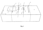
- FIG. 1 schematically shown apparatus for rotating flat goods 10 about an axis perpendicular to the plane 10 standing axis includes a (here only schematically illustrated) retraction device 17 which moves the goods 10 linearly in the transport direction x.
- the feed device 17 may be, for example, a conveyor belt, in particular a vacuum belt, or - as shown in the figures - for transport rollers or the like.
- the device further comprises a first rotary device 1 and a second rotary device 2 arranged in the transport direction x downstream of the intake device 17.
- the second rotary device 2 is followed by a transport device 18 and a trailer device 9 in the transport direction x (which is shown here only schematically).
- the two rotating devices 1, 2 are constructed substantially identical and each comprise rotating means 1a, 1b; 2a, 2b for rotating the Guts 10.
- the good is rotated by a predetermined first rotation angle ⁇ 1 and in the second rotator 2, the material 10 is later rotated by a predetermined second rotation angle ⁇ 2.
- the rotating means of the two rotating means 1 and 2 include in the in FIG. 1 shown embodiment, in each case a first pair of rotary rollers 1a and 2a and a second pair of rotary rollers 1b and 2b.
- the first rotary roller pair 1a, 2a and the second rotary roller pair 1b, 2b are each arranged in the transverse direction y to the transport direction x at a lateral distance y1 and y2 to each other.
- Each rotary roller pair 1a, 2a; 1b, 2b in each case comprises an upper roller and a lower roller, which each have a transverse direction y extending axis are rotatably mounted. Between each upper roller and the associated lower roller, a gap is formed in which the material 10 can be brought into engagement.
- each rotary roller pair 1a, 1b and 2a, 2b is either the upper roller and / or the lower roller with a motor 3a, 3b; 4a, 4b and is driven in rotation by this motor.
- a motor 3a, 3b; 4a, 4b For rotating a stock 10, which has been brought into engagement with the first pair of rotary rollers 1a and the second pair of rotary rollers 1b of the first rotating means 1, the rollers of the first pair of rotary rollers 1a and the rollers of the second pair of rotary rollers 1b at different speeds from the respective associated motor 3a , 3b are driven.
- the material 10 in engagement with the first rotary device 1 is rotated by a predetermined angle of rotation ⁇ 1.
- the rotation angle ⁇ 1 depends on the differential speed between the first pair of rotary rollers 1a and the second pair of rotary rollers 1b. Accordingly, a material 10, which is in engagement with the pair of pairs of rotary rollers 2a and 2b of the second rotary device 2, can be rotated by a predetermined angle of rotation ⁇ 2 by moving the rollers of the first roller roller pair 2a and the rollers of the second rotary roller pair 2b from the associated motors 4a, 4b are driven at different speeds.
- the rotating roller pairs 1a, 2a or 1b, 2b located on one side with respect to the longitudinal center plane of the device are driven at a constant predetermined speed, which expediently corresponds to the transport speed of the intake device 17.
- the laterally opposed and corresponding pair of rotary rollers is driven at a lower or higher speed, thereby causing rotation of the Guts 10.
- the rotating means 1a, 1b; 2a 2b of the first and the second rotating means can also each at the same speed of the associated motors 3a, 3b; 4a, 4b are driven.
- the rotating means 1a, 1b; 2a 2b shows a linear movement of the material 10 (without rotation) in the transport direction x when the product is in engagement with the rotation means 1a, 1b of the first rotation device 1 or with the rotation means 2a, 2b of the second rotation device 2.
- the rotating means 1a, 1b; 2a 2b of the first and the second rotating means are each assigned switchable engagement means 5 and 6.
- the rotation means 1a, 1b of the first rotating means 1 and the rotation means 2a 2b of second rotary device 2 are each brought into or out of engagement with a good 10 each independently.
- a control device (not illustrated here).
- the times and phases are determined in which the goods in or out of engagement with the rotating means 1a, 1b; 2a 2b of the first and the second rotating device is brought.
- the controller also determines at what speeds the motors 3a, 3b and 4a, 4b of the first and second rotors respectively run. This can be controlled via the control device, whether the rotating means 1a, 1b; 2a 2b of the first and second rotating means rotate at different or equal speeds to either rotate the product or linearly transport it without rotation.
- the switchable engagement means 5 and 6 may be, for example, hydraulic or pneumatic cylinders or motors which comprise the rotation means 1a, 1b; 2a 2b bring the first and the second rotating device in or out of engagement with the estate.
- the rotating means are each formed by corresponding rollers, for example, one of the rollers is coupled to an associated engagement means 5 and 6, respectively, and the engagement means 5 and 6, respectively, can move the corresponding rollers toward and away from each other to move them in or out Intervention with the estate 10 to bring.
- ⁇ which may be 90 °, for example, in the FIGS. 1 and 2 shown device operated as follows ( FIG. 3 ):
- the intake device 17 moves the goods 10 located in a first orientation a expediently at a constant speed linearly in the transport direction x to the first rotary device 1 (FIG. FIGS. 3a and 3b ).
- the first rotating device 1 takes over the moving material 10, in that the switchable engagement means 5 of the first rotating device 1 brings the rotating means 1a, 1b into engagement with the goods 10. After the takeover of the Guts 10 by the first rotating device 1 this transports the Good 10 while maintaining the (suitably constant) transport speed initially over a predetermined inlet path in the transport direction x linearly.
- the pairs of rotary rollers 1a, 1b of the first rotary device 1 are driven by the associated motors 3a, 3b at the same speed.
- the first rotary device 1 From a selectable point in time, which is predetermined by the control device, the first rotary device 1 starts rotating the material 10 in engagement therewith via a first rotation time t1 predetermined by the control device ( Figures 3c and 3d ) By changing the speed of one pair of rotary rollers 1a or 1b with respect to the other pair of rotary rollers 1b or 1a. Due to the different speeds of the first pair of rotary rollers 1a and of the second pair of rotary rollers 1b, the material 10 is rotated until a predetermined first angle of rotation ⁇ 1 is reached ( Figure 2d ).
- the first rotation angle ⁇ 1 which is conveyed to the material 10 in the first rotary device 1, depends on the difference between the speeds of the first pair of rotary rollers 1a and of the second pair of rotary rollers 1b of the first rotary device 1 and can be controlled accordingly by setting this differential speed. While the material 10 is rotated in the first rotator 1, it is not engaged with the pairs of rotary rollers 2a, 2b of the second rotator, as shown 3d figure seen.
- the product 10 In order to take over the workpiece 10 rotated by the first angle of rotation ⁇ 1, it is engaged by the second rotary device 2 ( FIG. 3f ) by bringing the material 10 into engagement with the rotating means 2a, 2b of the second rotating means 2.
- the product 10 remains in engagement with both turning means 1 and 2 during an overlapping time t3.
- the controller overlap time t3 bring the switchable engagement means 5 of the first rotating device 1, the Good 10 out of engagement with the rotation means 1a, 1b, for example, by moving the corresponding roles of pairs of rotary rolls 1a and 1b away from each other, as in FIG. 3h shown.
- the Good 10 is then only in engagement with the rotating means 2a and 2b of the second rotating device 2.
- the pairs of rotary rollers 2a, 2b of the second rotary device 2 are driven at different speeds during a second rotational period t2, as a result of which the material 10 in the second rotary device 2 continues to be rotated ( FIGS. 3j and 3k ).
- the rotation in the second rotating device 2 takes place until a predetermined second rotation angle ⁇ 2 is reached ( FIG. 3j ). This depends on the differential speed of the pairs of rotary rollers 2a, 2b of the second rotary device 2, which is adjusted accordingly.
- the speeds of the first pair of rotary rollers 2a and of the second pair of rotary rollers 2b of the second rotary device 2 are again matched to one another and driven at the same speed by the associated motors 4a, 4b.
- the good 10 () rotated by the total rotation angle ⁇ ⁇ 1 + ⁇ 2 FIG. 3j ) in the second rotary device 2 by a predetermined outlet distance linearly in the transport direction x.
- the speed of this linear movement of the material 10, which is then in its second orientation b also takes place expediently with the transport speed predetermined by the intake device 17.
- the material 10 can be rotated thereby, for example, from a first orientation a portrait in a second orientation b in landscape orientation.
- the second rotary device 2 leads the material 10 rotated by the total angle of rotation ⁇ finally to the downstream transport device 18 ( FIG. 3f ). This takes over the now located in the second orientation b Good 10 and transported it linearly in the transport direction x to a subsequent Nachiquer sensible 9 (Fig. Figures 3l and 3m ).
- the follower device 9 can be, for example, an alignment device with which a fine alignment of the orientation and the position of the rotated material 10 is carried out.
- the Nachauerr sexual 9 may also be a device for further processing of Guts 10, such. B. a collection station or a folding station or an inserting device, which introduces the turned material 10 into an envelope.
- the rotating means of the first and second rotating means are each formed by circulating vacuum bands 1a, 1b and 2a, 2b, wherein corresponding vacuum bands 1a, 1b and 2a, 2b in the transverse direction y in one lateral distance to each other are arranged and are driven at different speeds or at the same speeds to rotate the goods 10 or to transport it linearly.
- the vacuum bands 1a, 1b; 2a, 2b can be acted upon by engaging means 5, 6 switched on or off with negative pressure to suck a located on the respective vacuum belt Good 10 and bring into engagement with the respective rotating device 1, 2.
- the engagement means 5 and 6 are pumps and associated pump lines with switchable valves, which can apply negative pressure to the vacuum bands 1a, 1b on and off.
- the rotating means of the first rotating device 1 and / or the second rotating device 2 can be configured differently.
- cooperating pairs of rotary rollers 1a, 2a; 1b, 2b can be used as a rotating means, for example, with conveyor belts or belts and thus cooperating roles.
- any means which can impart a defined rotation to a moving material 10 can be used as the rotating means.
- sensors in particular optical sensors, can be used in the devices according to the invention to detect the position and optionally an orientation of the item 10 in different phases of the turning operation.
- Exemplary is in Figure 3c a sensor 16 for detecting the front edge of the Guts 10 is shown.
- the signals detected by the sensors are in this case transmitted to the control device for controlling the rotary devices 1, 2 and in particular for controlling the motors 3a, 3b; 4a, 4b used which the Driving means of rotation of the first rotator 1 and the second rotator 2 drive.
- the entire turning process has been divided into two sub-steps, namely in a first sub-step in the first rotating device 1 and a second sub-step in the second rotating device 2. It is also possible to divide the overall turning process into more than two sub-steps and for this purpose provide further rotating devices, which then connect in the transport direction x to the second rotating device 2 and the subsequent transport device 18 and / or are arranged in front of the first rotating device 1.
Landscapes
- Engineering & Computer Science (AREA)
- Mechanical Engineering (AREA)
- Registering Or Overturning Sheets (AREA)
- Attitude Control For Articles On Conveyors (AREA)
Abstract
Description
- Die Erfindung betrifft eine Vorrichtung zum Drehen von in einer Transportrichtung bewegten flachen Gütern nach dem Oberbegriff des Anspruchs 1 sowie ein entsprechendes Verfahren nach dem Oberbegriff des Anspruchs 2.
- Vorrichtungen der gattungsgemäßen Art werden beispielsweise in papierverarbeitenden Maschinen, wie z. B. Kuvertiermaschinen, Druckern oder Kopierern eingesetzt. Bei dem zu drehenden Gut kann es sich beispielsweise um einzelne Blätter oder Bögen oder um einen Blattstapel aus wenigstens zwei Blättern handeln. Gattungsgemäße Vorrichtungen können jedoch auch zum Drehen von anderen flachen Gütern verwendet werden, wie z. B. zum Drehen von Kunststofffolien, Kartonbögen oder dergleichen oder auch zum Drehen von verbundenen oder gehefteten Blättern in Form von Katalogen, Broschüren, Heften oder ähnlichen Produkten.
- Aus der
US3758104 ist eine Vorrichtung zum Drehen von rechteckigen Kartonbögen um 90° bekannt, welche in einer vorgegebenen Orientierung zur Weiterverarbeitung in einem Behälter abgelegt werden. Diese bekannte Vorrichtung umfasst ein Transportband, welches mit einer ersten Geschwindigkeit in einer Transportrichtung bewegt wird, um die um einen Winkel von 90° zu drehenden Kartonbögen in einer ersten Orientierung zu einer Dreheinrichtung zu bewegen. Die Dreheinrichtung weist einen ersten Spalt und einen zweiten Spalt auf, wobei ein erster Abschnitt des zu drehenden Kartonbogens in Eingriff mit dem ersten Spalt und ein zweiter Abschnitt des Kartonbogens in Eingriff mit dem zweiten Spalt gebracht wird. Der erste Spalt weist dabei eine erste Andrückwalze auf, welche zwischen ihrem Außenumfang und dem Transportband einen Spalt definiert, in dem der erste Abschnitt des Kartonbogens in Eingriff gebracht wird. Der zweite Spalt ist durch ein Drehrollenpaar mit einer angetriebenen Drehrolle und einer Andrückrolle definiert, zwischen deren Außenumfang der zweite Abschnitt des zu drehenden Kartonbogens eingreift. Die angetriebene Rolle des Drehrollenpaars wird zum Drehen des Kartonbogens mit einer Geschwindigkeit angetrieben, welche unterschiedlich zur Transportgeschwindigkeit der Transportbahn ist. - Die
EP 0 814 041 B1 offenbart ein Verfahren zur Drehung von Bogen von einer ersten Orientierung in eine dazu senkrechte Orientierung sowie eine Bogenstapelvorrichtung, in der zu stapelnde Bogen gemäß dem Verfahren von einer ersten Orientierung in eine dazu senkrecht stehende Orientierung gedreht werden. Die zu drehenden Bogen werden während des Drehens gleichmäßig zwischen einer stromaufwärts und einer stromabwärts gelegenen Position bewegt und in einer dazwischen liegenden Bewegungsphase differentiell bewegt, ohne dass die Geschwindigkeitskomponente in Bogenlaufrichtung geändert wird. In der dazwischenlegenden Bewegungsphase (Drehphase) wird der Bogen mit einem Geschwindigkeits-Zeit-Profil bewegt, welches eine erste Geschwindigkeitsfunktion enthält, bei der die Bewegungsgeschwindigkeit vorübergehend um einen vorbestimmten Betrag erhöht wird und eine zweite Geschwindigkeitsfunktion, bei der die Bewegungsgeschwindigkeit vorübergehend um den selben vorbestimmten Betrag und zur gleichen Zeit vorübergehend verringert wird, um dadurch den Bogen um einen Drehwinkel zu drehen, wobei der Betrag des Drehwinkels durch die Dauer der erhöhten bzw. verringerten Bewegungsgeschwindigkeit bestimmt wird. Gleichzeitig mit der Drehung des Bogens erfolgt eine seitliche Verschiebung, welche dadurch bestimmt wird, dass der Zeitpunkt zu dem die Drehung des Bogens eingeleitet wird, bezüglich dem Eintreffen des Bogens an einem festen Bezugspunkt geeignet ausgewählt wird. Die Drehung des Bogens erfolgt dabei mittels einer Dreheinrichtung, welche transversal zur Bogenlaufrichtung voneinander beabstandete Rollenpaare aufweist, die von einem Schrittmotor angetrieben werden, um die vorgegebenen Geschwindigkeits-Zeit-Profile der Rollenpaare zu erzeugen. - Diese aus dem Stand der Technik bekannten Vorrichtungen und Verfahren zum Drehen von flachen Gütern wie Blätter, Blattstapel oder Bögen können wegen der beim Drehvorgang auftretenden Beschleunigungen und Verzögerungen nur bei vergleichsweise geringen Transportgeschwindigkeiten des zu drehenden Guts eingesetzt werden. In modernen papierverarbeitenden Maschinen mit hohen Durchsatzzahlen in der Größenordnung von 100.000 Gütern pro Stunde müssen die zu drehenden Güter beim Drehvorgang stark abgebremst und wieder beschleunigt werden, wenn der Drehvorgang um einen vorgegebenen Drehwinkel, der beispielsweise 90° beträgt, in einem einzigen Drehschritt ausgeführt wird. Zur Vermeidung von starken Verzögerungen und Beschleunigungen des Guts ist es aus dem Stand der Technik bereits bekannt, den gesamten Drehvorgang in zwei oder mehr Teilschritte aufzuteilen.
- Die Aufteilung des gesamten Drehvorgangs in zwei oder mehr Teilschritte ermöglicht bei sehr hoher Taktleistung bzw. sinkender Zykluszeit, dass mehr Zeit und mehr Raum für die einzelnen Drehvorgänge zur Verfügung steht. Die Taktleistung kann bei einer Aufteilung des gesamten Drehvorgangs in zwei oder mehr Teilschritte erhöht werden, weil bereits das nachfolgende Gut in die erste Dreheinrichtung eingeführt werden kann, während sich das vorausgehende Gut noch im Drehvorgang in einer nachgeordneten Dreheinrichtung befindet.
- So ist beispielsweise aus der
DE 3718206 A1 eine Fördervorrichtung zum Drehen von entlang einer Wendestrecke bewegten Blattstapeln bekannt, welche einen Wendeförderer umfasst, der aus in zwei Bahnen nebeneinander verlaufenden und mit unterschiedlichen Geschwindigkeiten angetriebenen Förderbändern besteht, wobei eine erste Bahn ein mit einer ersten Geschwindigkeit antreibbares und umlaufendes Förderband aufweist und die zweite Bahn in Förderrichtung hintereinander wenigstens zwei umlaufende Förderer aufweist, welche mit einer von der ersten Geschwindigkeit unterschiedlichen Geschwindigkeit angetrieben werden. Durch die unterschiedlichen Geschwindigkeiten der ersten Bahn und der mehreren Förderer der zweiten Bahn erfolgt eine Drehung der auf den beiden Bahnen aufliegenden Blattstapel um einen vorgegebenen Drehwinkel, der von der Differenz der Geschwindigkeiten der ersten Bahn und der zweiten Bahn abhängt. Die Förderbänder der ersten und der zweiten Bahn sind dabei auf ihrer die Blattstapel tragenden Oberseite jeweils mit Borsten versehen, um eine gute Haftung zwischen der Oberseite der Förderbänder und der Unterseite der Blattstapel zu gewährleisten. Die Haftung des Blattstapels am Förderband liegt dabei permanent vor. Dies kann beim Übergang eines Blattstapels von einem Förderer der zweiten Bahn auf einen nachfolgenden Förderer der zweiten Bahn zu Problemen führen, da der Blattstapel zumindest kurzzeitig gleichzeitig mit zwei Förderern in Eingriff steht, welche jeweils ein ggf. unterschiedliches Drehmoment auf den Blattstapel ausüben. Dies kann zu Stauchungen oder Dehnungen der Blätter oder zu einem Verrutschen des Blattstapels führen. - Aus der
US2009/0107892A1 ist eine Vorrichtung zum Drehen von Poststücken von einer ersten Orientierung in eine zweite Orientierung bekannt, welche entlang einer Transportbahn bewegt werden. Die Vorrichtung umfasst mehrere in Transportrichtung hintereinander angeordnete Rollenpaare, welche in Querrichtung zur Transportrichtung im Abstand zueinander angeordnet sind. Die in transversalem Abstand zueinander angeordneten Rollenpaare werden zum Drehen der Poststücke mit unterschiedlichen Geschwindigkeiten angetrieben, wobei dem Poststück in jedem der Rollenpaare eine Drehung um einen vorgegebenen Drehwinkel vermittelt wird, der von der Differenzgeschwindigkeit der Rollenpaare abhängt, welche für jedes Rollenpaar unterschiedlich sein kann. Die Anordnung der Rollenpaare umfasst am Beginn und am Ende jeweils ein Rollenpaar, mit dem das Poststück nicht gedreht sondern in Transportrichtung linear weiterbewegt wird. Während der Drehung eines Poststücks durch die in transversalem Abstand zueinander angeordneten Rollenpaare wird das Poststück in Transportrichtung weiterbewegt. Der laterale Abstand von korrespondierenden Rollen eines Rollenpaars kann dabei eingestellt werden, um eine definierte Drehung des Poststücks in dem betreffenden Rollenpaar zu erzeugen und einen Versatz des Poststücks einzustellen. - Die bekannten Drehvorrichtungen und Verfahren, in denen der gesamte Drehvorgang in wenigstens zwei Teilschritten durchgeführt wird, erweisen sich allerdings als nachteilig, weil der Abstand der Drehpunkte in lateraler Richtung (Transportrichtung) fest vorgegeben ist und nicht angepasst werden kann. Dies ist insbesondere dann nachteilig, wenn mit derselben Drehvorrichtung Güter, beispielsweise Blätter, mit unterschiedlichen Formaten verarbeitet werden sollen. Weiterhin besteht bei den bekannten Drehvorrichtungen und Verfahren, in denen der gesamte Drehvorgang in Teilschritten in mehreren hintereinander angeordneten Dreheinrichtungen durchgeführt wird, die Gefahr, dass es bei der Übergabe des Guts von einer Dreheinrichtung an die nachfolgende Dreheinrichtung zu Stauchungen oder Dehnungen des Guts kommt, welche das Gut beschädigen oder zu Störungen in den Dreheinrichtungen führen können. In den bekannten Drehvorrichtungen sind die in Transportrichtung hintereinander liegenden Dreheinrichtungen in einem festen und kurzen Abstand zueinander angeordnet. Dies führt insbesondere bei der Verarbeitung von Gütern mit größeren Abmessungen dazu, dass sich ein Gut gleichzeitig in Eingriff mit zwei benachbarten Dreheinrichtungen befinden kann, was dazu führt, dass das Gut gedehnt, gestaucht oder verbogen und dadurch beschädigt werden kann.
- Hiervon ausgehend liegt der Erfindung die Aufgabe zugrunde, eine Vorrichtung und ein Verfahren zum Drehen von in einer Transportrichtung bewegten flachen Gütern aufzuzeigen, mit denen Güter unterschiedlichen Formats mit einem möglichst hohen Durchsatz und möglichst störungsfrei verarbeitet werden können. Die zu drehenden Güter sollen dabei schonend behandelt werden, so dass es beim Drehvorgang nicht zu Beschädigungen des Guts kommen kann.
- Diese Aufgaben werden mit einer Vorrichtung mit den Merkmalen des Anspruchs 1 sowie mit dem Verfahren mit den Merkmalen des Anspruchs 2 gelöst. Bevorzugte Ausführungsformen der Vorrichtung und der Verfahren sind den abhängigen Ansprüchen zu entnehmen.
- In der erfindungsgemäßen Vorrichtung und dem erfindungsgemäßen Verfahren wird die Drehung eines Guts, das sich in einer Transportrichtung bewegt, um den vorgegebenen Gesamt-Drehwinkel in zwei oder mehr Teilschritte aufgeteilt, wobei jeder Teilschritt der Drehung in einer dafür vorgesehenen Dreheinrichtung erfolgt. Die erfindungsgemäße Vorrichtung enthält hierfür wenigstens eine erste Dreheinrichtung und eine zweite Dreheinrichtung, welche in Transportrichtung hintereinander und im Abstand zueinander angeordnet sind und jeweils Drehmittel umfassen, welche das Gut zum Drehen in Eingriff nehmen. In der ersten Dreheinrichtung wird das Gut um einen ersten Drehwinkel und in der zweiten Dreheinrichtung um einen zweiten Drehwinkel und gegebenenfalls in weiteren, in Transportrichtung hintereinander angeordneten Dreheinrichtungen um weitere Drehwinkel gedreht, bis der Gesamt-Drehwinkel erreicht ist. Gemäß der Erfindung umfasst zumindest die erste und die zweite Dreheinrichtung und zweckmäßig jede weitere ggf. vorhandene Dreheinrichtung schaltbare Eingriffsmittel, mit denen die Drehmittel zu ausgewählten Zeitpunkten in oder außer Eingriff mit dem Gut gebracht werden können. Dadurch kann der Drehvorgang in der ersten Dreheinrichtung und der zweiten Dreheinrichtung entkoppelt und sicher gestellt werden, dass sich das Gut während eines Drehvorgangs immer nur mit einer Dreheinrichtung in Eingriff befindet, so dass es nicht zu Stauchungen, Dehnungen oder Verwindungen des Guts kommen kann.
- Durch das Entkoppeln der Drehvorgänge in der ersten Dreheinrichtung und der zweiten Dreheinrichtung kann ferner der Abstand der Drehpunkte unabhängig vom Format des Guts gewählt werden. Weiterhin kann der Beginn des Drehvorgangs in der ersten bzw. der zweiten Dreheinrichtung beliebig ausgewählt und beispielsweise an das Format des Guts oder der nach dem Drehvorgang gewünschten Lage und Orientierung des Guts angepasst werden. Dadurch kann beispielsweise ein seitlicher Versatz des Guts in lateraler Richtung (quer zur Transportrichtung) eingestellt oder ausgeglichen werden. Durch das Aufteilen des gesamten Drehvorgangs um den Gesamt-Drehwinkel in wenigstens zwei Teilschritte, mit einem ersten Teilschritt, in dem das Gut um den ersten Drehwinkel gedreht wird und einem zweiten Teilschritt, in dem das Gut um den zweiten Drehwinkel gedreht wird, steht für die Gesamtdrehung eine längere Drehzeit zur Verfügung (bei gleichbleibender Transportgeschwindigkeit des Guts längs der Transportrichtung), weshalb große Beschleunigungen des Guts vor und nach den Drehvorgängen vermieden werden können.
- In dem erfindungsgemäßen Verfahren ist vorgesehen, dass die Drehmittel der ersten Dreheinrichtung zu ausgewählten Zeitpunkten durch schaltbare Eingriffsmittel außer Eingriff mit dem Gut gebracht werden, während sich das Gut in Eingriff mit den Drehmitteln der zweiten Dreheinrichtung befindet. Dadurch kann eine definierte Übergabe des Guts von der ersten Dreheinrichtung an die zweite Dreheinrichtung erfolgen, ohne dass das Gut gedehnt, gestaucht oder verbogen wird.
- Zur Drehung des Guts wird dieses zumindest während einer ersten Drehdauer (t1) von den schaltbaren Eingriffsmitteln in Eingriff mit den Drehmitteln der ersten Dreheinrichtung gebracht, um das Gut zunächst in der ersten Dreheinrichtung um einen ersten Drehwinkel (α1) zu drehen. Während dieser ersten Drehdauer (t1) bringen die schaltbaren Eingriffsmittel das Gut außer Eingriff mit den Drehmitteln der zweiten Dreheinrichtung, so dass das Gut nur mit der ersten Dreheinrichtung in Eingriff steht. Nach Ablauf der ersten Drehdauer (t1) wird das Gut dann wenigstens über eine zweite Drehdauer (t2) von den schaltbaren Eingriffsmitteln in Eingriff mit den Drehmitteln der zweiten Dreheinrichtung gebracht, um das Gut in der zweiten Dreheinrichtung um einen zweiten Drehwinkel zu drehen. Die schaltbaren Eingriffsmittel bringen das Gut während dieser zweiten Drehdauer (t2) außer Eingriff mit den Drehmitteln der ersten Dreheinrichtung, so dass das Gut nur mit der zweiten Dreheinrichtung in Eingriff steht. Nach Ablauf der ersten Drehdauer (t1) wird das Gut zweckmäßig zunächst ohne Drehung linear in Transportrichtung (x) weiter bewegt und anschließend an die zweite Dreheinrichtung übergeben, wobei zur Übergabe des Guts von der ersten Dreheinrichtung an die zweite Dreheinrichtung die schaltbaren Eingriffsmittel das Gut außer Eingriff mit den Drehmitteln der ersten Dreheinrichtung und in Eingriff mit den Drehmitteln der zweiten Dreheinrichtung bringen.
- Zur Übergabe des Guts von der ersten Dreheinrichtung an die zweite Dreheinrichtung schließt sich also zweckmäßig an den ersten Drehvorgang in der ersten Dreheinrichtung eine von der Drehphase entkoppelte Transportphase an, in der das um den ersten Drehwinkel gedrehte Gut zunächst (ohne Drehung) linear in Transportrichtung weiter transportiert und dann an die zweite Dreheinrichtung übergeben wird, indem die schaltbaren Eingriffsmittel die Drehmittel der ersten Dreheinrichtung außer Eingriff mit dem Gut und die Drehmittel der zweiten Dreheinrichtung in Eingriff mit dem Gut bringen. Dabei ist es zweckmäßig, wenn das Gut während einer Überlappungszeit sowohl in Eingriff mit den Drehmitteln der ersten Dreheinrichtung als auch in Eingriff mit den Drehmitteln der zweiten Dreheinrichtung gehalten wird und das Gut während dieser Überlappungszeit bevorzugt mit gleichbleibender Geschwindigkeit linear und ohne Drehung in Transportrichtung bewegt wird. Dies stellt sicher, dass das Gut zu jeder Zeit sicher mit mindestens einer Dreheinrichtung in Eingriff steht und während des gesamten Vorgangs mit gleichbleibender Geschwindigkeit in Transportrichtung weiterbewegt werden kann.
- Nach Übergabe an die zweite Dreheinrichtung wird das Gut bevorzugt zunächst ohne Drehung linear in Transportrichtung (x) weiter bewegt und anschließend während einer zweiten Drehdauer (t2) in der zweiten Dreheinrichtung um einen vorgegebenen zweiten Drehwinkel gedreht. Auf diese Weise wird das Gut in wenigstens zwei entkoppelten Drehphasen um einen Gesamt-Drehwinkel α gedreht, wobei die Summe des ersten Drehwinkels α1 und des zweiten Drehwinkels α2 dem Gesamt-Drehwinkel α entspricht, welcher bspw. 90° beträgt. Der gesamte Drehvorgang kann jedoch auch in mehr als zwei Drehphasen aufgeteilt werden, wozu sich dann weitere Dreheinrichtungen in Transportrichtung hinter der zweiten Dreheinrichtung anschließen.
- Bevorzugt wird der gesamte Drehvorgang in dem erfindungsgemäßen Verfahren auf zwei Teilschritte aufgeteilt, so dass die Summe des ersten Drehwinkels in dem ersten Drehvorgang und des zweiten Drehwinkels in dem zweiten Drehvorgang den gewünschten Gesamt-Drehwinkel ergibt. Der gewünschte Gesamt-Drehwinkel beträgt dabei beispielsweise 90°, wenn das zu drehende Gut von einer ersten Orientierung im Hochformat in eine zweite Orientierung im Querformat (oder umgekehrt) gedreht werden soll. Das erfindungsgemäße Verfahren ist jedoch nicht auf die Drehung von Gütern um einen Gesamt-Drehwinkel von 90° beschränkt. Vielmehr kann mit dem erfindungsgemäßen Verfahren jeder beliebige Drehwinkel erzielt werden. Der in den einzelnen Drehschritten erfolgende Drehwinkel (erster Drehwinkel, zweiter Drehwinkel und gegebenenfalls weitere Drehwinkel in weiteren Dreheinrichtungen der erfindungsgemäßen Vorrichtung) hängt dabei von einer Geschwindigkeitsdifferenz der Drehmittel in der ersten bzw. zweiten Dreheinrichtung oder gegebenenfalls weiteren vorhandenen Dreheinrichtungen ab.
- In einem bevorzugten Ausführungsbeispiel der Erfindung ist vorgesehen, dass jede Dreheinrichtung erste Drehmittel und zweite Drehmittel aufweist, welche in Querrichtung (y) zur Transportrichtung (x) in einem lateralen Abstand zueinander angeordnet sind und von einem Motor entweder mit unterschiedlichen Drehgeschwindigkeiten drehend angetrieben werden, um das Gut zu Drehen oder mit gleichen Drehgeschwindigkeiten drehend angetrieben werden, um das Gut (ohne Drehung) linear zu bewegen, während sich das Gut in Eingriff mit den Drehmitteln befindet. Bevorzugt ist der laterale Abstand der korrespondierenden Drehmittel der ersten Dreheinrichtung und/oder der zweiten Dreheinrichtung einstellbar und insbesondere an das Format des Guts anpassbar. Dies verbessert noch die Verwendung der erfindungsgemäßen Vorrichtung für das Drehen unterschiedlicher Gütern mit verschiedenen Formaten und Größen.
- Bei den Drehmitteln handelt es sich in einem Ausführungsbeispiel der Erfindung um Drehrollenpaare mit zueinander korrespondierenden Rollen. Die schaltbaren Eingriffsmittel sind dabei so eingerichtet, dass sie korrespondierende Rollen der Drehrollenpaare aufeinander zu bzw. voneinander weg bewegen, um das Gut in bzw. außer Eingriff mit den korrespondierenden Rollen der Drehrollenpaare zu bringen. In diesem Ausführungsbeispiel weisen die erste Dreheinrichtung und/oder die zweite Dreheinrichtung ein erstes Drehrollenpaar und ein zweites Drehrollenpaar auf, wobei das erste Drehrollenpaar und das zweite Drehrollenpaar in Querrichtung (y) zur Transportrichtung (x) in einem lateralen Abstand zueinander angeordnet sind und zum Drehen des Guts mit unterschiedlichen Drehgeschwindigkeiten von einem Motor drehend angetrieben werden.
- Bei den Drehmitteln handelt es sich in einem alternativen Ausführungsbeispiel der Erfindung um sich bewegende Transportbänder mit dazu korrespondierenden Drehrollen. In diesem Ausführungsbeispiel bewegen die schaltbaren Eingriffsmittel die Drehrollen auf das jeweils zugeordnete Transportband zu bzw. davon weg, um das Gut in bzw. außer Eingriff mit den Drehmitteln zu bringen.
- In einem weiteren alternativen Ausführungsbeispiel der Erfindung sind die Drehmittel von mit unterschiedlicher Geschwindigkeit antreibbaren Vakuumbändern gebildet, welche schaltbar mit Unterdruck beaufschlagbar sind. In diesem Ausführungsbeispiel beaufschlagen die schaltbaren Eingriffsmittel die Vakuumbänder mit Unterdruck, um das Gut in Eingriff mit den Vakuumbändern zu bringen. Um das Gut außer Eingriff mit den Vakuumbändern zu bringen wird der Unterdruck von den schaltbaren Eingriffsmitteln abgeschaltet.
- In Transportrichtung gesehen vor der ersten Dreheinrichtung kann zweckmäßig eine Einzugseinrichtung angeordnet sein, welche das sich in der ersten Orientierung befindliche Gut zunächst linear in Transportrichtung bewegt und dann an die erste Dreheinrichtung übergibt. In Transportrichtung gesehen nach der zweiten Dreheinrichtung kann gegebenenfalls eine weitere Transportrichtung angeordnet sein, welche das aus der zweiten Dreheinrichtung kommende Gut übernimmt und zunächst linear in Transportrichtung weiterbewegt und anschließend an eine gegebenenfalls vorhandene weitere Dreheinrichtung oder an eine andere Nachläufereinrichtung, wie z.B. eine Sammelstation oder eine Falzstation oder eine Kuvertiereinrichtung übergibt. Bei der Nachläufereinrichtung kann es sich insbesondere um eine Ausrichteinrichtung zum Ausrichten des Guts handeln. Mit einer solchen Ausrichteinrichtung können etwaige Winkelfehler, die bereits beim Einlauf des Guts in die erste Dreheinrichtung vorhanden waren, oder die während des Drehvorgangs in der ersten oder zweiten Dreheinrichtung entstanden sind, ausgeglichen werden, um das gedrehte Gut am Ende des gesamten Drehvorgangs in einer perfekten Lage und Orientierung zu erhalten.
- Diese und weitere Merkmale und Vorteile der Erfindung ergeben sich aus den nachfolgend unter Bezugnahme auf die begleitenden Zeichnungen näher beschriebenen Ausführungsbeispielen. Die Zeichnungen zeigen:
- Fig. 1:
- schematische Darstellung einer erfindungsgemäßen Vorrichtung zum Drehen von flachen Gütern in einer perspektivischen Draufsicht und in einer ersten Phase des erfindungsgemäßen Verfahrens,
- Fig. 2:
- schematische Darstellung der Vorrichtung von
Figur 1 in einer perspektivischen Seitenansicht und in einer ersten Phase des erfindungsgemäßen Verfahrens; - Fig. 3:
- schematische Darstellungen der Vorrichtung von
Figur 1 in verschiedenen Phasen des erfindungsgemäßen Verfahrens in einer perspektivischen Draufsicht (Figuren 3a ,3c ,3e ,3g ,3j ,3l ) und in einer perspektivischen Seitenansicht (Figuren 3b ,3d ,3f ,3h ,3k ,3m ); - Die in
Figur 1 schematisch dargestellte Vorrichtung zum Drehen von flachen Gütern 10 um eine senkrecht zur Ebene des Guts 10 stehende Achse umfasst eine (hier nur schematisch dargestellte) Einzugseinrichtung 17, welche die Güter 10 linear in Transportrichtung x bewegt. Bei der Einzugseinrichtung 17 kann es sich beispielsweise um ein Transportband, insbesondere ein Vakuumband, oder - wie in in den Figuren dargestellt - um Transportrollen oder dergleichen handeln. Die Vorrichtung umfasst weiterhin in Transportrichtung x nach der Einzugseinrichtung 17 angeordnet eine erste Dreheinrichtung 1 und eine zweite Dreheinrichtung 2. An die zweite Dreheinrichtung 2 schließt sich in Transportrichtung x eine Transporteinrichtung 18 sowie eine Nachläufereinrichtung 9 an (welche hier nur schematisch dargestellt ist). - In dem in
Figur 1 zeichnerisch dargestellten Ausführungsbeispiel sind die beiden Dreheinrichtungen 1, 2 im Wesentlichen identisch aufgebaut und umfassen jeweils Drehmittel 1a, 1b; 2a, 2b zum Drehen des Guts 10. In der ersten Dreheinrichtung 1 wird das Gut um einen vorgegebenen ersten Drehwinkel α1 gedreht und in der zweiten Dreheinrichtung 2 wird das Gut 10 später um einen vorgegebenen zweiten Drehwinkel α2 gedreht. Durch die Drehung des Guts 10 in der ersten Dreheinrichtung 1 um den ersten Drehwinkel α1 und anschließend in der zweiten Dreheinrichtung 2 um den zweiten Drehwinkel α2 erhält das Gut in der Vorrichtung eine Gesamtdrehung um einen Gesamt-Drehwinkel α = α1+α2. In vielen Anwendungen ist eine Drehung des Guts 10 um einen Gesamt-Drehwinkel von α=90° gefordert. In diesem Anwendungsfall können die beiden vorgegebenen Drehwinkel α1 und α2 beispielsweise symmetrisch zu α1=α2=45° gewählt werden. Es ist jedoch auch eine asymmetrische Aufteilung der beiden Teil-Drehungen in der ersten Dreheinrichtung 1 und der zweiten Dreheinrichtung 2 möglich, wie z. B. α1=30° und α2=60° oder umgekehrt. - Die Drehmittel der beiden Dreheinrichtungen 1 und 2 umfassen bei dem in
Figur 1 gezeigten Ausführungsbeispiel jeweils ein erstes Drehrollenpaar 1a bzw. 2a und ein zweites Drehrollenpaar 1b bzw. 2b. Das erste Drehrollenpaar 1a, 2a und das zweite Drehrollenpaar 1b, 2b sind dabei jeweils in Querrichtung y zur Transportrichtung x in einem lateralen Abstand y1 bzw. y2 zueinander angeordnet. Jedes Drehrollenpaar 1a, 2a; 1b, 2b umfasst dabei jeweils eine obere Rolle und eine untere Rolle, welche jeweils um eine in Querrichtung y verlaufende Achse drehbar gelagert sind. Zwischen jeder oberen Rolle und der ihr zugeordneten unteren Rolle ist ein Spalt ausgebildet, in dem das Gut 10 in Eingriff gebracht werden kann. Von jedem Drehrollenpaar 1a, 1b bzw. 2a, 2b ist entweder die obere Rolle und/oder die untere Rolle mit einem Motor 3a, 3b; 4a, 4b gekoppelt und wird von diesem Motor drehend angetrieben. Zum Drehen eines Guts 10, das in Eingriff mit dem ersten Drehrollenpaar 1a und dem zweiten Drehrollenpaar 1b der ersten Dreheinrichtung 1 gebracht worden ist, können die Rollen des ersten Drehrollenpaars 1a und die Rollen des zweiten Drehrollenpaars 1b mit unterschiedlichen Geschwindigkeiten von dem jeweils zugeordneten Motor 3a, 3b angetrieben werden. Beim Einstellen unterschiedlicher Geschwindigkeiten des ersten Drehrollenpaars 1a und des zweiten Drehrollenpaars 1b wird das sich im Eingriff mit der ersten Dreheinrichtung 1 befindliche Gut 10 um einen vorgegebenen Drehwinkel α1 gedreht. Der Drehwinkel α1 hängt dabei von der Differenzgeschwindigkeit zwischen dem ersten Drehrollenpaar 1a und dem zweiten Drehrollenpaar 1b ab. Entsprechend kann ein Gut 10, das in Eingriff mit den beiden Drehrollenpaaren 2a und 2b der zweiten Dreheinrichtung 2 steht, um einen vorgegebenen Drehwinkel α2 gedreht werden, indem die Rollen des ersten Drehrollenrollenpaars 2a und die Rollen des zweiten Drehrollenpaars 2b von den zugeordneten Motoren 4a, 4b mit unterschiedlichen Geschwindigkeiten angetrieben werden. Bevorzugt werden die sich auf einer Seite in Bezug auf die Längsmittelebene der Vorrichtung befindlichen Drehrollenpaare 1a, 2a oder 1b, 2b mit einer konstanten vorgegebenen Geschwindigkeit angetrieben, welche zweckmäßig der Transportgeschwindigkeit der Einzugseinrichtung 17 entspricht. Zum Drehen des Guts 10 wird dann das lateral dazu gegenüberliegende und korrespondierende Drehrollenpaar mit einer niedrigeren oder einer höheren Geschwindigkeit angetrieben, um dadurch eine Drehung des Guts 10 zu bewirken. - Die Drehmittel 1a, 1b; 2a 2b der ersten und der der zweiten Dreheinrichtung können auch jeweils mit derselben Geschwindigkeit von den zugeordneten Motoren 3a, 3b; 4a, 4b angetrieben werden. In diesem Fall erzeugen die Drehmittel 1a, 1b; 2a 2b eine lineare Bewegung des Guts 10 (ohne Drehung) in Transportrichtung x, wenn sich das Gut mit den Drehmitteln 1a, 1b der ersten Dreheinrichtung 1 bzw. mit den Drehmitteln 2a, 2b der zweiten Dreheinrichtung 2 in Eingriff befindet.
- Den Drehmitteln 1a, 1b; 2a 2b der ersten und der der zweiten Dreheinrichtung sind jeweils schaltbare Eingriffsmittel 5 und 6 zugeordnet. Über diese schaltbaren Eingriffsmittel 5 und 6 können die Drehmittel 1a, 1b der ersten Dreheinrichtung 1 und die Drehmittel 2a 2b der zweiten Dreheinrichtung 2 jeweils unabhängig voneinander in oder außer Eingriff mit einem Gut 10 gebracht werden. Zur Steuerung der schaltbaren Eingriffsmittel 5 und 6 sind diese mit einer (hier zeichnerisch nicht dargestellten) Steuereinrichtung gekoppelt. Über die Steuereinrichtung werden die Zeitpunkte und Phasen festgelegt, in denen das Gut in oder außer Eingriff mit den Drehmitteln 1a, 1b; 2a 2b der ersten bzw. der zweiten Dreheinrichtung gebracht wird. Die Steuereinrichtung legt auch fest, mit welchen Geschwindigkeiten die Motoren 3a, 3b und 4a, 4b der ersten bzw. der zweiten Dreheinrichtung laufen. Dadurch kann über die Steuereinrichtung gesteuert werden, ob sich die Drehmittel 1a, 1b; 2a 2b der ersten bzw. der zweiten Dreheinrichtung mit unterschiedlichen oder mit gleichen Geschwindigkeiten drehen, um das Gut entweder zu drehen oder ohne Drehung linear zu transportieren.
- Bei den schaltbaren Eingriffsmitteln 5 und 6 kann es sich bspw. um Hydraulik- oder Pneumatik-Zylinder oder um Motoren handeln, welche die Drehmittel 1a, 1b; 2a 2b der ersten bzw. der zweiten Dreheinrichtung in oder außer Eingriff mit dem Gut bringen. Wenn die Drehmittel jeweils durch korrespondierende Rollen gebildet sind, ist bspw. eine der Rollen an ein zugeordnetes Eingriffsmittel 5 bzw. 6 gekoppelt und das Eingriffsmittel 5 bzw. 6 kann die korrespondierenden Rollen aufeinander zu bzw. voneinander weg bewegen, um diese in bzw. außer Eingriff mit dem Gut 10 zu bringen.
- Zum Drehen eines Guts 10 um einen Gesamt-Drehwinkel α, der beispielsweise 90° betragen kann, wird die in den
Figuren 1 und2 gezeigte Vorrichtung wie folgt betrieben (Figur 3 ): - Die Einzugseinrichtung 17 bewegt das sich in einer ersten Orientierung a befindliche Gut 10 zweckmäßig mit konstanter Geschwindigkeit linear in Transportrichtung x zu der ersten Dreheinrichtung 1 (
Figuren 3a und 3b ). Die erste Dreheinrichtung 1 übernimmt das sich bewegende Gut 10, indem die schaltbaren Eingriffsmittel 5 der ersten Dreheinrichtung 1 die Drehmittel 1a, 1b in Eingriff mit dem Gut 10 bringt. Nach der Übernahme des Guts 10 durch die erste Dreheinrichtung 1 transportiert diese das Gut 10 unter Beibehaltung der (zweckmäßig konstanten) Transportgeschwindigkeit zunächst über eine vorgegebene Einlaufstrecke in Transportrichtung x linear weiter. Hierzu werden die Drehrollenpaare 1a, 1b der ersten Dreheinrichtung 1 von den zugeordneten Motoren 3a, 3b mit gleicher Geschwindigkeit angetrieben. Ab einem wählbaren Zeitpunkt, der von der Steuereinrichtung vorgegeben wird, beginnt die erste Dreheinrichtung 1 das sich mit dieser im Eingriff stehende Gut 10 über eine von der Steuereinrichtung vorgegebene erste Drehdauer t1 zu drehen (Figuren 3c und 3d ), indem die Geschwindigkeit eines Drehrollenpaars 1a oder 1b gegenüber dem anderen Drehrollenpaar 1b oder 1a verändert wird. Durch die unterschiedlichen Geschwindigkeiten des ersten Drehrollenpaars 1a und des zweiten Drehrollenpaars 1b wird das Gut 10 gedreht, bis ein vorgegebener erster Drehwinkel α1 erreicht ist (Figur 2d ). Der erste Drehwinkel α1, welcher dem Gut 10 in der ersten Dreheinrichtung 1 vermittelt wird, hängt dabei von der Differenz der Geschwindigkeiten des ersten Drehrollenpaars 1a und des zweiten Drehrollenpaars 1b der ersten Dreheinrichtung 1 ab und kann durch Einstellung dieser Differenzgeschwindigkeit entsprechend gesteuert werden. Während das Gut 10 in der ersten Dreheinrichtung 1 gedreht wird, befindet es sich nicht im Eingriff mit den Drehrollenpaaren 2a, 2b der zweiten Dreheinrichtung, wie ausFigur 3d ersichtlich. Wenn das Gut um den vorgegebenen ersten Drehwinkel α1 gedreht worden ist, wird die Geschwindigkeit des Drehrollenpaars 1a oder 1b wieder an die Geschwindigkeit des anderen Drehrollenpaars 1b oder 1a angeglichen, so dass beide Drehrollenpaare 1a, 1b der ersten Dreheinrichtung 1 wieder mit gleicher Geschwindigkeit angetrieben werden. Dadurch wird das Gut 10 in der ersten Transporteinrichtung 1 linear in Transportrichtung x weiter bewegt (Figuren 3e und 3f ). Zweckmäßig erfolgt auch dieser lineare Transport in der ersten Dreheinrichtung 1 mit der von der Einzugseinrichtung 17 vorgegebenen konstanten Transportgeschwindigkeit. Das Gut 10 wird auf diese Weise in der ersten Dreheinrichtung 1 um eine vorgegeben Auslaufstrecke linear in Transportrichtung x weiterbewegt und anschließend an die nachgeschaltete zweite Dreheinrichtung 2 übergeben. - Zur Übernahme des um den ersten Drehwinkel α1 gedrehten Guts 10 wird dieses von der zweiten Dreheinrichtung 2 in Eingriff genommen (
Figur 3f ), indem das Gut 10 in Eingriff mit den Drehmitteln 2a, 2b der zweiten Dreheinrichtung 2 gebracht wird. Zweckmäßig bleibt das Gut 10 während einer Überlappungszeit t3 mit beiden Dreheinrichtungen 1 und 2 im Eingriff. Nach Ablauf der von der Steuereinrichtung vorgegebenen Überlappungszeit t3 bringen die schaltbaren Eingriffsmittel 5 der ersten Dreheinrichtung 1 das Gut 10 außer Eingriff mit deren Drehmittel 1a, 1b, indem sie bspw. die korrespondierenden Rollen der Drehrollenpaare 1a und 1b voneinander weg bewegen, wie inFigur 3h gezeigt. Das Gut 10 befindet sich dann nur noch in Eingriff mit den Drehmitteln 2a und 2b der zweiten Dreheinrichtung 2. Diese werden zunächst noch mit gleicher Geschwindigkeit von den Motoren 4a, 4b angetrieben, um das Gut 10 (ohne Drehung) in der zweiten Dreheinrichtung 2 um eine vorgegebene Einlaufstrecke linear weiter zu bewegen (Figur 3g ). Sobald das Gut 10 die erste Dreheinrichtung 1 verlassen hat und nicht mehr mit den Drehmitteln 1a, 1b im Eingriff steht, kann bereits ein nachfolgendes Gut zur seriellen Verarbeitung der Güter an die erste Dreheinrichtung 1 übergeben und dort wie oben beschrieben gedreht werden. Dies führt zu einer erheblichen Verringerung der Zykluszeiten und damit zu einer Erhöhung der Taktleistung und des Durchsatzes. - Nach einer bestimmten, von der Steuereinrichtung vorgebbaren Zeitdauer werden die Drehrollenpaare 2a, 2b der zweiten Dreheinrichtung 2 während einer zweiten Drehdauer t2 mit unterschiedlichen Geschwindigkeiten angetrieben, wodurch das Gut 10 in der zweiten Dreheinrichtung 2 weiter gedreht wird (
Figuren 3j und 3k ). Die Drehung in der zweiten Dreheinrichtung 2 erfolgt solange, bis ein vorgegebener zweiter Drehwinkel α2 erreicht ist (Figur 3j ). Dieser hängt von der Differenzgeschwindigkeit der Drehrollenpaare 2a, 2b der zweiten Dreheinrichtung 2 ab, welche entsprechend eingestellt wird. Ist das Gut 10 in der zweiten Dreheinrichtung 2 um den vorgegebenen zweiten Drehwinkel α2 gedreht worden, werden die Geschwindigkeiten des ersten Drehrollenpaars 2a und des zweiten Drehrollenpaars 2b der zweiten Dreheinrichtung 2 wieder aneinander angeglichen und mit gleicher Geschwindigkeit von den zugeordneten Motoren 4a, 4b angetrieben. Dadurch wird das dann um den Gesamt-Drehwinkel α = α1+α2 gedrehte Gut 10 (Figur 3j ) in der zweiten Dreheinrichtung 2 um eine vorgegebene Auslaufstrecke linear in Transportrichtung x weiterbewegt. Die Geschwindigkeit dieser linearen Bewegung des dann sich in seiner zweiten Orientierung b befindlichen Guts 10, erfolgt auch hier zweckmäßig mit der von der Einzugseinrichtung 17 vorgegebenen Transportgeschwindigkeit. Bei einer Drehung des Guts 10 um einen Gesamt-Drehwinkel von α = 90° kann das Gut 10 dadurch beispielsweise von einer ersten Orientierung a im Hochformat in eine zweite Orientierung b im Querformat gedreht werden. - Die zweite Dreheinrichtung 2 führt das um den Gesamtdrehwinkel α gedrehte Gut 10 schließlich der nachgeschalteten Transporteinrichtung 18 zu (
Figur 3f ). Diese übernimmt das sich nun in der zweiten Orientierung b befindliche Gut 10 und transportiert es linear in Transportrichtung x zu einer sich anschließenden Nachläufereinrichtung 9 (Figuren 3l und 3m ). Bei der Nachläufereinrichtung 9 kann es sich beispielsweise um eine Ausrichteinrichtung handeln, mit der eine Feinausrichtung der Orientierung und der Lage des gedrehten Guts 10 durchgeführt wird. Bei der Nachläufereinrichtung 9 kann es sich auch um eine Vorrichtung zur Weiterverarbeitung des Guts 10 handeln, wie z. B. eine Sammelstation oder eine Falzstation oder eine Kuvertiereinrichtung, welche das gedrehte Gut 10 in einen Umschlag einführt. - In einer weiteren, hier zeichnerisch nicht dargestellten Ausführungsform einer erfindungsgemäßen Vorrichtung sind die Drehmittel der ersten und der zweiten Dreheinrichtung jeweils durch umlaufende Vakuumbänder 1a, 1b und 2a, 2b gebildet, wobei korrespondierende Vakuumbänder 1a, 1b bzw. 2a, 2b in Querrichtung y in einem lateralen Abstand zueinander angeordnet sind und mit unterschiedlichen Geschwindigkeiten oder mit gleichen Geschwindigkeiten angetrieben werden, um das Gut 10 zu drehen oder es linear zu transportieren. Die Vakuumbänder 1a, 1b; 2a, 2b können dabei von Eingriffsmitteln 5, 6 an- bzw. abschaltbar mit Unterdruck beaufschlagt werden, um ein sich auf dem jeweiligen Vakuumband befindliches Gut 10 anzusaugen und in Eingriff mit der jeweiligen Dreheinrichtung 1, 2 zu bringen. Bei den Eingriffsmitteln 5 und 6 handelt es sich dabei um Pumpen und zugehörige Pumpleitungen mit schaltbaren Ventilen, welche die Vakuumbänder 1a, 1b an- und abschaltbar mit Unterdruck beaufschlagen können.
- Die Erfindung ist nicht auf die hier zeichnerisch dargestellten Ausführungsbeispiele beschränkt. So können beispielsweise die Drehmittel der ersten Dreheinrichtung 1 und/oder der zweiten Dreheinrichtung 2 anders ausgestaltet sein. Statt zusammenwirkender Drehrollenpaare 1a, 2a; 1b, 2b können als Drehmittel beispielsweise auch mit Transportbändern oder -riemen und damit kooperierende Rollen verwendet werden. Grundsätzlich können als Drehmittel jegliche Einrichtungen verwendet werden, welche einem sich bewegenden Gut 10 eine definierte Drehung vermitteln können. Es ist weiterhin möglich die Drehmittel der ersten und/oder der zweiten Dreheinrichtung 1 bzw. 2 so auszubilden, dass diese einzeln und unabhängig voneinander das Gut in und außer Eingriff nehmen können. So kann bspw. realisiert werden, dass nur das Drehmittel 1a, nicht jedoch das dazu korrespondierende Drehmittel 1b der ersten Dreheinrichtung 1 das Gut in Eingriff nimmt.
- Ergänzend können in den erfindungsgemäßen Vorrichtungen Sensoren, insbesondere optische Sensoren, verwendet werden, um die Lage und gegebenenfalls eine Orientierung des Guts 10 in verschiedenen Phasen des Drehvorgangs zu erfassen. Beispielhaft ist in
Figur 3c ein Sensor 16 zur Erfassung der Vorderkante des Guts 10 dargestellt. Die von den Sensoren erfassten Signale werden hierbei an die Steuereinrichtung zur Steuerung der Dreheinrichtungen 1, 2 übermittelt und insbesondere zur Steuerung der Motoren 3a, 3b; 4a, 4b verwendet, welche die Drehmittel der ersten Dreheinrichtung 1 bzw. der zweiten Dreheinrichtung 2 antreiben. Durch die Verwendung solcher Sensoren ist es beispielsweise möglich, die Orientierung des Guts 10 in Zwischenstufen des Drehvorgangs zu erfassen und in den nachfolgenden Stufen zu korrigieren, falls eine Fehlorientierung durch die Sensoren erfasst worden ist. - In den hier beschriebenen Ausführungsbeispielen ist der gesamte Drehvorgang in zwei Teilschritte aufgeteilt worden, nämlich in einem ersten Teilschritt in der ersten Dreheinrichtung 1 und einem zweiten Teilschritt in der zweiten Dreheinrichtung 2. Es ist auch möglich, den Gesamtdrehvorgang in mehr als zwei Teilschritte aufzuteilen und hierfür weitere Dreheinrichtungen vorzusehen, welche sich dann in Transportrichtung x an die zweite Dreheinrichtung 2 bzw. die nachfolgende Transporteinrichtung 18 anschließen und/oder vor der ersten Dreheinrichtung 1 angeordnet sind.
Claims (12)
- Vorrichtung zum Drehen von in einer Transportrichtung (x) bewegten flachen Gütern (10), insbesondere von Blättern oder Blattstapeln, von einer ersten Orientierung (a) in eine zweite Orientierung (b) um einen vorgegebenen Gesamt-Drehwinkel (α), mit einer ersten Dreheinrichtung (1), in der das Gut (10) zunächst um einen ersten Drehwinkel (α1) gedreht wird und mit mindestens einer zweiten Dreheinrichtung (2), in der das Gut (10) später um einen zweiten Drehwinkel (α2) gedreht wird, wobei die erste Dreheinrichtung (1) und die zweite Dreheinrichtung (2) in Transportrichtung (x) hintereinander angeordnet sind und jede Dreheinrichtung (1, 2) Drehmittel (1a, 1b; 2a, 2b) umfasst, welche das Gut (10) zum Drehen in Eingriff nehmen, dadurch gekennzeichnet, dass zumindest die erste Dreheinrichtung (1) schaltbare Eingriffsmittel (5, 6) aufweist, mit denen die Drehmittel (1a, 1b; 2a, 2b) zu ausgewählten Zeitpunkten in oder außer Eingriff mit dem Gut (10) gebracht werden können.
- Verfahren zum Drehen von in einer Transportrichtung (x) bewegten flachen Gütern (10), insbesondere von Blättern oder Blattstapeln, von einer ersten Orientierung (a) in eine zweite Orientierung (b) um einen vorgegebenen Gesamt-Drehwinkel (α), mit einer ersten Dreheinrichtung (1), in der das Gut (10) zunächst um einen ersten Drehwinkel (α1) gedreht wird und mit mindestens einer zweiten Dreheinrichtung (2), in der das Gut (10) später um einen zweiten Drehwinkel (α2) gedreht wird, wobei die erste Dreheinrichtung (1) und die zweite Dreheinrichtung (2) in Transportrichtung (x) hintereinander angeordnet sind und jede Dreheinrichtung (1, 2) Drehmittel (1a, 1b; 2a, 2b) umfasst, welche das Gut (10) zum Drehen in Eingriff nehmen, dadurch gekennzeichnet, dass die Drehmittel (1a, 1b) der ersten Dreheinrichtung (1) zu ausgewählten Zeitpunkten durch schaltbare Eingriffsmittel (5) außer Eingriff mit dem Gut (10) gebracht werden, während sich das Gut (10) in Eingriff mit den Drehmitteln (2a, 2b) der zweiten Dreheinrichtung (2) befindet.
- Vorrichtung oder Verfahren nach Anspruch 1 oder 2, dadurch gekennzeichnet, dass jede Dreheinrichtung (1, 2) erste Drehmittel (1a; 2a) und zweite Drehmittel (1b; 2b) aufweist, welche in Querrichtung (y) zur Transportrichtung (x) in einem lateralen Abstand (y1; y2) zueinander angeordnet sind und von einem Motor (3a, 3b; 4a, 4b) mit unterschiedlichen Drehgeschwindigkeiten drehend angetrieben werden, um das Gut (10) zu Drehen oder mit gleichen Drehgeschwindigkeiten drehend angetrieben werden, um das Gut (10) linear zu bewegen, wenn sich das Gut (10) in Eingriff mit den Drehmitteln (1a, 1b; 2a, 2b) befindet.
- Vorrichtung oder Verfahren nach einem der Ansprüche 1 bis 3, dadurch gekennzeichnet, dass das Gut (10) zumindest während einer ersten Drehdauer (t1) von den schaltbaren Eingriffsmitteln (5) in Eingriff mit den Drehmitteln (1a, 1b) der ersten Dreheinrichtung (1) gebracht wird, um das Gut (10) in der ersten Dreheinrichtung (1) um einen ersten Drehwinkel (α1) zu drehen, und dass die schaltbaren Eingriffsmittel (6) während dieser ersten Drehdauer (t1) das Gut (10) außer Eingriff mit den Drehmitteln (2a, 2b) der zweiten Dreheinrichtung (2) bringen.
- Vorrichtung oder Verfahren nach Anspruch 4, dadurch gekennzeichnet, dass das Gut (10) nach Ablauf der ersten Drehdauer (t1) und wenigstens über eine zweite Drehdauer (t2) von den schaltbaren Eingriffsmitteln (6) in Eingriff mit den Drehmitteln (2a, 2b) der zweiten Dreheinrichtung (2) gebracht wird, um das Gut (10) in der zweiten Dreheinrichtung (2) um einen zweiten Drehwinkel (α2) zu drehen, und dass die schaltbaren Eingriffsmittel (5) während dieser zweiten Drehdauer (t2) das Gut (10) außer Eingriff mit den Drehmitteln (1a, 1b) der ersten Dreheinrichtung (1) bringen.
- Vorrichtung oder Verfahren nach einem der Ansprüche 4 oder 5, dadurch gekennzeichnet, dass das Gut (10) nach Ablauf der ersten Drehdauer (t1) in der ersten Dreheinrichtung (1) zunächst ohne Drehung linear in Transportrichtung (x) weiter bewegt und anschließend an die zweite Dreheinrichtung (2) übergeben wird, wobei zur Übergabe des Guts (10) von der ersten Dreheinrichtung (1) an die zweite Dreheinrichtung (2) die schaltbaren Eingriffsmittel (5, 6) das Gut (10) außer Eingriff mit den Drehmitteln (1a, 1b) der ersten Dreheinrichtung (1) und in Eingriff mit den Drehmitteln (2a, 2b) der zweiten Dreheinrichtung (2) bringen.
- Vorrichtung oder Verfahren nach einem der Ansprüche 1 bis 6, dadurch gekennzeichnet, dass bei der Übergabe des Guts (10) von der ersten Dreheinrichtung (1) an die zweite Dreheinrichtung (2) die schaltbaren Eingriffsmittel (5, 6) das Gut (10) während einer Überlappungszeit (t3) sowohl in Eingriff mit den Drehmitteln (1a, 1b) der ersten Dreheinrichtung (1) als auch in Eingriff mit den Drehmitteln (2a, 2b) der zweiten Dreheinrichtung (2) halten, wobei das Gut (10) während der Überlappungszeit (t3) bevorzugt mit gleichbleibender Geschwindigkeit linear und ohne Drehung in Transportrichtung (x) bewegt wird.
- Vorrichtung oder Verfahren nach Anspruch 6 oder 7, dadurch gekennzeichnet, dass das Gut (10) nach Übergabe an die zweite Dreheinrichtung (2) zunächst ohne Drehung linear in Transportrichtung (x) weiter bewegt und anschließend während einer zweiten Drehdauer (t2) in der zweiten Dreheinrichtung (2) um einen zweiten Drehwinkel (α2) gedreht wird.
- Vorrichtung oder Verfahren nach einem der voranstehenden Ansprüche, dadurch gekennzeichnet, dass die Summe des ersten Drehwinkels (α1) und des zweiten Drehwinkels (α2) kleiner oder gleich dem Gesamt-Drehwinkel (α) ist, welcher insbesondere 90° beträgt.
- Vorrichtung oder Verfahren nach einem der voranstehenden Ansprüche, dadurch gekennzeichnet, dass es sich bei den Drehmitteln um Drehrollenpaare (1a, 1b; 2a, 2b) mit zueinander korrespondierenden Rollen handelt und dass die schaltbaren Eingriffsmittel (5, 6) korrespondierende Rollen der Drehrollenpaare aufeinander zu bzw. voneinander weg bewegen, um das Gut (10) in bzw. außer Eingriff mit den korrespondierenden Rollen der Drehrollenpaare (1a, 1b; 2a, 2b) zu bringen.
- Vorrichtung oder Verfahren nach einem der Ansprüche 3 bis 10, dadurch gekennzeichnet, dass der laterale Abstand (y1, y2) der korrespondierenden Drehmittel (1a, 1b; 2a, 2b) der ersten Dreheinrichtung (1) und/oder der zweiten Dreheinrichtung (2) einstellbar und insbesondere an das Format des Guts (10) anpassbar ist.
- Vorrichtung oder Verfahren nach einem der voranstehenden Ansprüche, dadurch gekennzeichnet, dass in Transportrichtung (x) vor der ersten Dreheinrichtung (1) eine Einzugseinrichtung (17) angeordnet ist, welche das sich in der ersten Orientierung (a) befindliche Gut (10) linear in Transportrichtung (x) bewegt und an die erste Dreheinrichtung (1) übergibt und dass in Transportrichtung (x) nach der zweiten Dreheinrichtung (2) eine Transporteinrichtung (18) angeordnet ist, welche das aus der zweiten Dreheinrichtung (2) kommende Gut (10) übernimmt und linear in Transportrichtung (x) weiter bewegt und an eine ggf. vorhandene weitere Dreheinrichtung oder an eine Nachläufereinrichtung (9), insbesondere eine Ausrichteinrichtung zum Ausrichten des Guts (10) übergibt.
Applications Claiming Priority (1)
| Application Number | Priority Date | Filing Date | Title |
|---|---|---|---|
| DE102012112718.2A DE102012112718A1 (de) | 2012-12-20 | 2012-12-20 | Vorrichtung und Verfahren zum Drehen von flachen Gütern |
Publications (3)
| Publication Number | Publication Date |
|---|---|
| EP2746204A2 true EP2746204A2 (de) | 2014-06-25 |
| EP2746204A3 EP2746204A3 (de) | 2017-03-01 |
| EP2746204B1 EP2746204B1 (de) | 2018-05-16 |
Family
ID=49765314
Family Applications (1)
| Application Number | Title | Priority Date | Filing Date |
|---|---|---|---|
| EP13195686.4A Active EP2746204B1 (de) | 2012-12-20 | 2013-12-04 | Vorrichtung und Verfahren zum Drehen von flachen Gütern |
Country Status (3)
| Country | Link |
|---|---|
| US (1) | US9187261B2 (de) |
| EP (1) | EP2746204B1 (de) |
| DE (1) | DE102012112718A1 (de) |
Families Citing this family (2)
| Publication number | Priority date | Publication date | Assignee | Title |
|---|---|---|---|---|
| US10315376B2 (en) * | 2012-11-08 | 2019-06-11 | The C.W. Zumbiel Company | System and associated method for digital scoring of carton blanks |
| CN104960894A (zh) * | 2015-06-04 | 2015-10-07 | 广西北流市红日紫砂陶瓷厂 | 一种陶瓷板转向输送装置 |
Citations (4)
| Publication number | Priority date | Publication date | Assignee | Title |
|---|---|---|---|---|
| US3758104A (en) | 1971-09-23 | 1973-09-11 | W Daily | Turning apparatus |
| DE3718206A1 (de) | 1987-05-29 | 1988-12-15 | Will E C H Gmbh & Co | Vorrichtung zum foerdern und drehen von papierstapeln |
| EP0814041B1 (de) | 1996-06-17 | 2001-11-14 | C.P. Bourg S.A. | Verfahren zum Drehen von Bögen und Blattstapler mit einer Blattdrehungseinrichtung |
| US20090107892A1 (en) | 2007-10-31 | 2009-04-30 | Pitney Bowes Inc. | Sheet material transposition for sorting apparatus |
Family Cites Families (8)
| Publication number | Priority date | Publication date | Assignee | Title |
|---|---|---|---|---|
| DE8519708U1 (de) * | 1985-07-08 | 1985-09-12 | Maschinenbau Louise GmbH, 5000 Köln | Leiteinrichtung an einer Vorrichtung zum Palettieren von gefüllten Säcken od.dgl. |
| DE4125342C2 (de) * | 1991-07-31 | 2002-11-14 | Adolf Stambera | Positioniereinrichtung für Palettiermaschinen |
| NL1013670C2 (nl) | 1999-11-25 | 2001-05-28 | Ocu Technologies B V | Werkwijze voor het in zijdelings register brengen van een vel met een daarop over te dragen beeld. |
| JP4845658B2 (ja) * | 2006-04-07 | 2011-12-28 | キヤノン株式会社 | シート搬送装置およびこれを備えた画像形成装置 |
| JP4795134B2 (ja) * | 2006-06-26 | 2011-10-19 | キヤノン株式会社 | シート搬送装置及び画像形成装置及び画像読取装置 |
| US7669842B2 (en) * | 2006-08-22 | 2010-03-02 | Xerox Corporation | Sheet rotator |
| JP4922079B2 (ja) * | 2007-06-20 | 2012-04-25 | 株式会社東芝 | 紙葉類処理装置 |
| US8584832B2 (en) * | 2009-12-07 | 2013-11-19 | Pitney Bowes Inc. | System and method for mailpiece skew correction |
-
2012
- 2012-12-20 DE DE102012112718.2A patent/DE102012112718A1/de not_active Withdrawn
-
2013
- 2013-12-04 EP EP13195686.4A patent/EP2746204B1/de active Active
- 2013-12-19 US US14/134,241 patent/US9187261B2/en active Active
Patent Citations (4)
| Publication number | Priority date | Publication date | Assignee | Title |
|---|---|---|---|---|
| US3758104A (en) | 1971-09-23 | 1973-09-11 | W Daily | Turning apparatus |
| DE3718206A1 (de) | 1987-05-29 | 1988-12-15 | Will E C H Gmbh & Co | Vorrichtung zum foerdern und drehen von papierstapeln |
| EP0814041B1 (de) | 1996-06-17 | 2001-11-14 | C.P. Bourg S.A. | Verfahren zum Drehen von Bögen und Blattstapler mit einer Blattdrehungseinrichtung |
| US20090107892A1 (en) | 2007-10-31 | 2009-04-30 | Pitney Bowes Inc. | Sheet material transposition for sorting apparatus |
Also Published As
| Publication number | Publication date |
|---|---|
| DE102012112718A1 (de) | 2014-06-26 |
| EP2746204A3 (de) | 2017-03-01 |
| EP2746204B1 (de) | 2018-05-16 |
| US9187261B2 (en) | 2015-11-17 |
| US20140178170A1 (en) | 2014-06-26 |
Similar Documents
| Publication | Publication Date | Title |
|---|---|---|
| EP1854750B1 (de) | Vorrichtung zum Wenden von kontinuierlich geförderten, flachliegenden Druckprodukten | |
| EP2411309B1 (de) | Verfahren zum betreiben eines ein falzmesser und einen falztisch aufweisenden längsfalzapparates und längsfalzapparat | |
| DE102008048287A1 (de) | Vorrichtung und Verfahren zum Falzen von Bogen | |
| EP1341712B1 (de) | Vorrichtungen zur ausrichtung von bogen | |
| EP2883820B1 (de) | Vorrichtung und Verfahren zum Eintakten von Buchblocks | |
| EP2935060B1 (de) | Vorrichtung und verfahren zum drehen von flachen gütern | |
| EP3533609B1 (de) | Vorrichtung und verfahren zur weiterverarbeitung sequenziell bedruckter druckbogen | |
| EP2133295B1 (de) | Vorrichtung und Verfahren zum Entnehmen flacher Druckprodukte aus einem Stapel und zum Übergeben der Druckprodukte an eine laufende Transportvorrichtung | |
| EP1528023B1 (de) | Verfahren und Vorrichtung zur Wandlung eines Förderstromes von flachen Gegenständen | |
| EP2746204B1 (de) | Vorrichtung und Verfahren zum Drehen von flachen Gütern | |
| EP2055660B1 (de) | Vorrichtung zum getakteten Umlenken von flächigen Gegenständen | |
| EP2867148A1 (de) | Drehvorrichtung für flächige erzeugnisse oder für einen stapel davon | |
| EP2559549B1 (de) | Vorrichtung und Verfahren zum Bearbeiten von Bogen aus Papier oder einem anderen flexiblen Material | |
| DE102020107836B4 (de) | Bogenverarbeitende Maschine mit einem Bogentrenner | |
| CH701621A1 (de) | Vorrichtung und Verfahren zum Ablegen von Produkten. | |
| EP1661833B1 (de) | Verfahren und Vorrichtung zum Verarbeiten von Druckereierzeugnissen | |
| EP3957582A1 (de) | Vorrichtung und verfahren zum zuführen von flächenförmigen gütern zu einer bearbeitungseinheit | |
| DE102020107837A1 (de) | Bogenverarbeitende Maschine mit einem Bogentrenner | |
| EP2192057B1 (de) | Vorrichtung zum Transportieren von Produkten | |
| DE19608939A1 (de) | Einrichtung zur Vereinzelung und Beschleunigung von Druckprodukten | |
| DE102020107838A1 (de) | Bogenverarbeitende Maschine mit einem Bogentrenner | |
| CH701619A1 (de) | Vorrichtung und Verfahren zum Falzen von Druckereiprodukten. | |
| DE102015004857A1 (de) | Verfahren und Vorrichtung zum Beladen einer Dreimesserschneidemaschine mit Schneidgut | |
| EP2660171A2 (de) | Saugtransportvorrichtung und Verfahren zur Abnahme eines Bogens von einem Bogenstapel | |
| WO2011063855A1 (de) | Papiersammel- und stapeleinrichtung |
Legal Events
| Date | Code | Title | Description |
|---|---|---|---|
| PUAI | Public reference made under article 153(3) epc to a published international application that has entered the european phase |
Free format text: ORIGINAL CODE: 0009012 |
|
| 17P | Request for examination filed |
Effective date: 20131204 |
|
| AK | Designated contracting states |
Kind code of ref document: A2 Designated state(s): AL AT BE BG CH CY CZ DE DK EE ES FI FR GB GR HR HU IE IS IT LI LT LU LV MC MK MT NL NO PL PT RO RS SE SI SK SM TR |
|
| AX | Request for extension of the european patent |
Extension state: BA ME |
|
| PUAL | Search report despatched |
Free format text: ORIGINAL CODE: 0009013 |
|
| AK | Designated contracting states |
Kind code of ref document: A3 Designated state(s): AL AT BE BG CH CY CZ DE DK EE ES FI FR GB GR HR HU IE IS IT LI LT LU LV MC MK MT NL NO PL PT RO RS SE SI SK SM TR |
|
| AX | Request for extension of the european patent |
Extension state: BA ME |
|
| RIC1 | Information provided on ipc code assigned before grant |
Ipc: B65H 7/08 20060101ALI20170125BHEP Ipc: B65H 9/00 20060101ALI20170125BHEP Ipc: B65H 5/06 20060101AFI20170125BHEP |
|
| R17P | Request for examination filed (corrected) |
Effective date: 20170901 |
|
| RBV | Designated contracting states (corrected) |
Designated state(s): AL AT BE BG CH CY CZ DE DK EE ES FI FR GB GR HR HU IE IS IT LI LT LU LV MC MK MT NL NO PL PT RO RS SE SI SK SM TR |
|
| RIC1 | Information provided on ipc code assigned before grant |
Ipc: B65H 5/06 20060101AFI20171219BHEP Ipc: B65H 7/08 20060101ALI20171219BHEP Ipc: B65H 9/00 20060101ALI20171219BHEP |
|
| GRAP | Despatch of communication of intention to grant a patent |
Free format text: ORIGINAL CODE: EPIDOSNIGR1 |
|
| INTG | Intention to grant announced |
Effective date: 20180205 |
|
| GRAS | Grant fee paid |
Free format text: ORIGINAL CODE: EPIDOSNIGR3 |
|
| GRAA | (expected) grant |
Free format text: ORIGINAL CODE: 0009210 |
|
| AK | Designated contracting states |
Kind code of ref document: B1 Designated state(s): AL AT BE BG CH CY CZ DE DK EE ES FI FR GB GR HR HU IE IS IT LI LT LU LV MC MK MT NL NO PL PT RO RS SE SI SK SM TR |
|
| REG | Reference to a national code |
Ref country code: GB Ref legal event code: FG4D Free format text: NOT ENGLISH |
|
| REG | Reference to a national code |
Ref country code: CH Ref legal event code: EP Ref country code: CH Ref legal event code: NV Representative=s name: LUCHS AND PARTNER AG PATENTANWAELTE, CH |
|
| REG | Reference to a national code |
Ref country code: IE Ref legal event code: FG4D Free format text: LANGUAGE OF EP DOCUMENT: GERMAN |
|
| REG | Reference to a national code |
Ref country code: DE Ref legal event code: R096 Ref document number: 502013010140 Country of ref document: DE |
|
| REG | Reference to a national code |
Ref country code: AT Ref legal event code: REF Ref document number: 999346 Country of ref document: AT Kind code of ref document: T Effective date: 20180615 |
|
| REG | Reference to a national code |
Ref country code: NL Ref legal event code: MP Effective date: 20180516 |
|
| REG | Reference to a national code |
Ref country code: LT Ref legal event code: MG4D |
|
| PG25 | Lapsed in a contracting state [announced via postgrant information from national office to epo] |
Ref country code: NO Free format text: LAPSE BECAUSE OF FAILURE TO SUBMIT A TRANSLATION OF THE DESCRIPTION OR TO PAY THE FEE WITHIN THE PRESCRIBED TIME-LIMIT Effective date: 20180816 Ref country code: FI Free format text: LAPSE BECAUSE OF FAILURE TO SUBMIT A TRANSLATION OF THE DESCRIPTION OR TO PAY THE FEE WITHIN THE PRESCRIBED TIME-LIMIT Effective date: 20180516 Ref country code: BG Free format text: LAPSE BECAUSE OF FAILURE TO SUBMIT A TRANSLATION OF THE DESCRIPTION OR TO PAY THE FEE WITHIN THE PRESCRIBED TIME-LIMIT Effective date: 20180816 Ref country code: SE Free format text: LAPSE BECAUSE OF FAILURE TO SUBMIT A TRANSLATION OF THE DESCRIPTION OR TO PAY THE FEE WITHIN THE PRESCRIBED TIME-LIMIT Effective date: 20180516 Ref country code: LT Free format text: LAPSE BECAUSE OF FAILURE TO SUBMIT A TRANSLATION OF THE DESCRIPTION OR TO PAY THE FEE WITHIN THE PRESCRIBED TIME-LIMIT Effective date: 20180516 Ref country code: ES Free format text: LAPSE BECAUSE OF FAILURE TO SUBMIT A TRANSLATION OF THE DESCRIPTION OR TO PAY THE FEE WITHIN THE PRESCRIBED TIME-LIMIT Effective date: 20180516 |
|
| PG25 | Lapsed in a contracting state [announced via postgrant information from national office to epo] |
Ref country code: RS Free format text: LAPSE BECAUSE OF FAILURE TO SUBMIT A TRANSLATION OF THE DESCRIPTION OR TO PAY THE FEE WITHIN THE PRESCRIBED TIME-LIMIT Effective date: 20180516 Ref country code: HR Free format text: LAPSE BECAUSE OF FAILURE TO SUBMIT A TRANSLATION OF THE DESCRIPTION OR TO PAY THE FEE WITHIN THE PRESCRIBED TIME-LIMIT Effective date: 20180516 Ref country code: LV Free format text: LAPSE BECAUSE OF FAILURE TO SUBMIT A TRANSLATION OF THE DESCRIPTION OR TO PAY THE FEE WITHIN THE PRESCRIBED TIME-LIMIT Effective date: 20180516 Ref country code: NL Free format text: LAPSE BECAUSE OF FAILURE TO SUBMIT A TRANSLATION OF THE DESCRIPTION OR TO PAY THE FEE WITHIN THE PRESCRIBED TIME-LIMIT Effective date: 20180516 Ref country code: GR Free format text: LAPSE BECAUSE OF FAILURE TO SUBMIT A TRANSLATION OF THE DESCRIPTION OR TO PAY THE FEE WITHIN THE PRESCRIBED TIME-LIMIT Effective date: 20180817 |
|
| PG25 | Lapsed in a contracting state [announced via postgrant information from national office to epo] |
Ref country code: EE Free format text: LAPSE BECAUSE OF FAILURE TO SUBMIT A TRANSLATION OF THE DESCRIPTION OR TO PAY THE FEE WITHIN THE PRESCRIBED TIME-LIMIT Effective date: 20180516 Ref country code: PL Free format text: LAPSE BECAUSE OF FAILURE TO SUBMIT A TRANSLATION OF THE DESCRIPTION OR TO PAY THE FEE WITHIN THE PRESCRIBED TIME-LIMIT Effective date: 20180516 Ref country code: RO Free format text: LAPSE BECAUSE OF FAILURE TO SUBMIT A TRANSLATION OF THE DESCRIPTION OR TO PAY THE FEE WITHIN THE PRESCRIBED TIME-LIMIT Effective date: 20180516 Ref country code: CZ Free format text: LAPSE BECAUSE OF FAILURE TO SUBMIT A TRANSLATION OF THE DESCRIPTION OR TO PAY THE FEE WITHIN THE PRESCRIBED TIME-LIMIT Effective date: 20180516 Ref country code: DK Free format text: LAPSE BECAUSE OF FAILURE TO SUBMIT A TRANSLATION OF THE DESCRIPTION OR TO PAY THE FEE WITHIN THE PRESCRIBED TIME-LIMIT Effective date: 20180516 Ref country code: SK Free format text: LAPSE BECAUSE OF FAILURE TO SUBMIT A TRANSLATION OF THE DESCRIPTION OR TO PAY THE FEE WITHIN THE PRESCRIBED TIME-LIMIT Effective date: 20180516 |
|
| REG | Reference to a national code |
Ref country code: DE Ref legal event code: R097 Ref document number: 502013010140 Country of ref document: DE |
|
| PG25 | Lapsed in a contracting state [announced via postgrant information from national office to epo] |
Ref country code: SM Free format text: LAPSE BECAUSE OF FAILURE TO SUBMIT A TRANSLATION OF THE DESCRIPTION OR TO PAY THE FEE WITHIN THE PRESCRIBED TIME-LIMIT Effective date: 20180516 Ref country code: IT Free format text: LAPSE BECAUSE OF FAILURE TO SUBMIT A TRANSLATION OF THE DESCRIPTION OR TO PAY THE FEE WITHIN THE PRESCRIBED TIME-LIMIT Effective date: 20180516 |
|
| PLBE | No opposition filed within time limit |
Free format text: ORIGINAL CODE: 0009261 |
|
| STAA | Information on the status of an ep patent application or granted ep patent |
Free format text: STATUS: NO OPPOSITION FILED WITHIN TIME LIMIT |
|
| 26N | No opposition filed |
Effective date: 20190219 |
|
| PG25 | Lapsed in a contracting state [announced via postgrant information from national office to epo] |
Ref country code: SI Free format text: LAPSE BECAUSE OF FAILURE TO SUBMIT A TRANSLATION OF THE DESCRIPTION OR TO PAY THE FEE WITHIN THE PRESCRIBED TIME-LIMIT Effective date: 20180516 |
|
| GBPC | Gb: european patent ceased through non-payment of renewal fee |
Effective date: 20181204 |
|
| PG25 | Lapsed in a contracting state [announced via postgrant information from national office to epo] |
Ref country code: LU Free format text: LAPSE BECAUSE OF NON-PAYMENT OF DUE FEES Effective date: 20181204 Ref country code: MC Free format text: LAPSE BECAUSE OF FAILURE TO SUBMIT A TRANSLATION OF THE DESCRIPTION OR TO PAY THE FEE WITHIN THE PRESCRIBED TIME-LIMIT Effective date: 20180516 |
|
| REG | Reference to a national code |
Ref country code: IE Ref legal event code: MM4A |
|
| REG | Reference to a national code |
Ref country code: BE Ref legal event code: MM Effective date: 20181231 |
|
| PG25 | Lapsed in a contracting state [announced via postgrant information from national office to epo] |
Ref country code: IE Free format text: LAPSE BECAUSE OF NON-PAYMENT OF DUE FEES Effective date: 20181204 Ref country code: FR Free format text: LAPSE BECAUSE OF NON-PAYMENT OF DUE FEES Effective date: 20181231 |
|
| PG25 | Lapsed in a contracting state [announced via postgrant information from national office to epo] |
Ref country code: AL Free format text: LAPSE BECAUSE OF FAILURE TO SUBMIT A TRANSLATION OF THE DESCRIPTION OR TO PAY THE FEE WITHIN THE PRESCRIBED TIME-LIMIT Effective date: 20180516 Ref country code: BE Free format text: LAPSE BECAUSE OF NON-PAYMENT OF DUE FEES Effective date: 20181231 |
|
| PG25 | Lapsed in a contracting state [announced via postgrant information from national office to epo] |
Ref country code: GB Free format text: LAPSE BECAUSE OF NON-PAYMENT OF DUE FEES Effective date: 20181204 |
|
| PG25 | Lapsed in a contracting state [announced via postgrant information from national office to epo] |
Ref country code: MT Free format text: LAPSE BECAUSE OF FAILURE TO SUBMIT A TRANSLATION OF THE DESCRIPTION OR TO PAY THE FEE WITHIN THE PRESCRIBED TIME-LIMIT Effective date: 20180516 |
|
| REG | Reference to a national code |
Ref country code: AT Ref legal event code: MM01 Ref document number: 999346 Country of ref document: AT Kind code of ref document: T Effective date: 20181204 |
|
| PG25 | Lapsed in a contracting state [announced via postgrant information from national office to epo] |
Ref country code: TR Free format text: LAPSE BECAUSE OF FAILURE TO SUBMIT A TRANSLATION OF THE DESCRIPTION OR TO PAY THE FEE WITHIN THE PRESCRIBED TIME-LIMIT Effective date: 20180516 |
|
| PG25 | Lapsed in a contracting state [announced via postgrant information from national office to epo] |
Ref country code: AT Free format text: LAPSE BECAUSE OF NON-PAYMENT OF DUE FEES Effective date: 20181204 |
|
| PG25 | Lapsed in a contracting state [announced via postgrant information from national office to epo] |
Ref country code: PT Free format text: LAPSE BECAUSE OF FAILURE TO SUBMIT A TRANSLATION OF THE DESCRIPTION OR TO PAY THE FEE WITHIN THE PRESCRIBED TIME-LIMIT Effective date: 20180516 |
|
| PG25 | Lapsed in a contracting state [announced via postgrant information from national office to epo] |
Ref country code: MK Free format text: LAPSE BECAUSE OF NON-PAYMENT OF DUE FEES Effective date: 20180516 Ref country code: HU Free format text: LAPSE BECAUSE OF FAILURE TO SUBMIT A TRANSLATION OF THE DESCRIPTION OR TO PAY THE FEE WITHIN THE PRESCRIBED TIME-LIMIT; INVALID AB INITIO Effective date: 20131204 Ref country code: CY Free format text: LAPSE BECAUSE OF FAILURE TO SUBMIT A TRANSLATION OF THE DESCRIPTION OR TO PAY THE FEE WITHIN THE PRESCRIBED TIME-LIMIT Effective date: 20180516 |
|
| PG25 | Lapsed in a contracting state [announced via postgrant information from national office to epo] |
Ref country code: IS Free format text: LAPSE BECAUSE OF FAILURE TO SUBMIT A TRANSLATION OF THE DESCRIPTION OR TO PAY THE FEE WITHIN THE PRESCRIBED TIME-LIMIT Effective date: 20180916 |
|
| P01 | Opt-out of the competence of the unified patent court (upc) registered |
Effective date: 20230515 |
|
| PGFP | Annual fee paid to national office [announced via postgrant information from national office to epo] |
Ref country code: CH Payment date: 20250101 Year of fee payment: 12 |
|
| REG | Reference to a national code |
Ref country code: CH Ref legal event code: U11 Free format text: ST27 STATUS EVENT CODE: U-0-0-U10-U11 (AS PROVIDED BY THE NATIONAL OFFICE) Effective date: 20260101 |
|
| PGFP | Annual fee paid to national office [announced via postgrant information from national office to epo] |
Ref country code: DE Payment date: 20251211 Year of fee payment: 13 |