EP2746464B1 - Chargeuse à pneus - Google Patents
Chargeuse à pneus Download PDFInfo
- Publication number
- EP2746464B1 EP2746464B1 EP12867723.4A EP12867723A EP2746464B1 EP 2746464 B1 EP2746464 B1 EP 2746464B1 EP 12867723 A EP12867723 A EP 12867723A EP 2746464 B1 EP2746464 B1 EP 2746464B1
- Authority
- EP
- European Patent Office
- Prior art keywords
- air cleaner
- cab
- engine
- disposed
- exhaust gas
- Prior art date
- Legal status (The legal status is an assumption and is not a legal conclusion. Google has not performed a legal analysis and makes no representation as to the accuracy of the status listed.)
- Not-in-force
Links
Images






Classifications
-
- E—FIXED CONSTRUCTIONS
- E02—HYDRAULIC ENGINEERING; FOUNDATIONS; SOIL SHIFTING
- E02F—DREDGING; SOIL-SHIFTING
- E02F9/00—Component parts of dredgers or soil-shifting machines, not restricted to one of the kinds covered by groups E02F3/00 - E02F7/00
- E02F9/08—Superstructures; Supports for superstructures
-
- E—FIXED CONSTRUCTIONS
- E02—HYDRAULIC ENGINEERING; FOUNDATIONS; SOIL SHIFTING
- E02F—DREDGING; SOIL-SHIFTING
- E02F9/00—Component parts of dredgers or soil-shifting machines, not restricted to one of the kinds covered by groups E02F3/00 - E02F7/00
- E02F9/08—Superstructures; Supports for superstructures
- E02F9/0858—Arrangement of component parts installed on superstructures not otherwise provided for, e.g. electric components, fenders, air-conditioning units
- E02F9/0866—Engine compartment, e.g. heat exchangers, exhaust filters, cooling devices, silencers, mufflers, position of hydraulic pumps in the engine compartment
-
- B—PERFORMING OPERATIONS; TRANSPORTING
- B60—VEHICLES IN GENERAL
- B60K—ARRANGEMENT OR MOUNTING OF PROPULSION UNITS OR OF TRANSMISSIONS IN VEHICLES; ARRANGEMENT OR MOUNTING OF PLURAL DIVERSE PRIME-MOVERS IN VEHICLES; AUXILIARY DRIVES FOR VEHICLES; INSTRUMENTATION OR DASHBOARDS FOR VEHICLES; ARRANGEMENTS IN CONNECTION WITH COOLING, AIR INTAKE, GAS EXHAUST OR FUEL SUPPLY OF PROPULSION UNITS IN VEHICLES
- B60K13/00—Arrangement in connection with combustion air intake or gas exhaust of propulsion units
- B60K13/02—Arrangement in connection with combustion air intake or gas exhaust of propulsion units concerning intake
-
- E—FIXED CONSTRUCTIONS
- E02—HYDRAULIC ENGINEERING; FOUNDATIONS; SOIL SHIFTING
- E02F—DREDGING; SOIL-SHIFTING
- E02F9/00—Component parts of dredgers or soil-shifting machines, not restricted to one of the kinds covered by groups E02F3/00 - E02F7/00
- E02F9/08—Superstructures; Supports for superstructures
- E02F9/0833—Improving access, e.g. for maintenance, steps for improving driver's access, handrails
-
- E—FIXED CONSTRUCTIONS
- E02—HYDRAULIC ENGINEERING; FOUNDATIONS; SOIL SHIFTING
- E02F—DREDGING; SOIL-SHIFTING
- E02F9/00—Component parts of dredgers or soil-shifting machines, not restricted to one of the kinds covered by groups E02F3/00 - E02F7/00
- E02F9/08—Superstructures; Supports for superstructures
- E02F9/0858—Arrangement of component parts installed on superstructures not otherwise provided for, e.g. electric components, fenders, air-conditioning units
- E02F9/0883—Tanks, e.g. oil tank, urea tank, fuel tank
-
- E—FIXED CONSTRUCTIONS
- E02—HYDRAULIC ENGINEERING; FOUNDATIONS; SOIL SHIFTING
- E02F—DREDGING; SOIL-SHIFTING
- E02F9/00—Component parts of dredgers or soil-shifting machines, not restricted to one of the kinds covered by groups E02F3/00 - E02F7/00
- E02F9/16—Cabins, platforms, or the like, for drivers
-
- F—MECHANICAL ENGINEERING; LIGHTING; HEATING; WEAPONS; BLASTING
- F02—COMBUSTION ENGINES; HOT-GAS OR COMBUSTION-PRODUCT ENGINE PLANTS
- F02M—SUPPLYING COMBUSTION ENGINES IN GENERAL WITH COMBUSTIBLE MIXTURES OR CONSTITUENTS THEREOF
- F02M35/00—Combustion-air cleaners, air intakes, intake silencers, or induction systems specially adapted for, or arranged on, internal-combustion engines
- F02M35/16—Combustion-air cleaners, air intakes, intake silencers, or induction systems specially adapted for, or arranged on, internal-combustion engines characterised by use in vehicles
- F02M35/164—Heavy duty vehicles, e.g. trucks, trains, agricultural or construction machines
Definitions
- the present invention relates to a wheel loader and in particular to a wheel loader equipped with an air cleaner.
- An exhaust gas post-processing device is mounted on a wheel loader.
- the exhaust gas post-processing device includes a diesel particulate filtering device that collects and removes particulate matter of soot and the like included in the diesel engine exhaust gas.
- the diesel particulate filtering device is mounted in a row with an air cleaner on an upper portion of the engine.
- a nitrogen oxide reduction catalyst device may also be provided to remove NOx from the exhaust gas.
- the nitrogen oxide reduction catalyst device is provided on the exhaust downstream side of the diesel particulate filtering device.
- the installation location of the nitrogen oxide reduction catalyst device becomes a problem if the nitrogen oxide reduction catalyst device is installed in addition to the diesel particulate filtering device. Since the nitrogen oxide reduction catalyst device needs to be disposed on the exhaust downstream side of the diesel particulate filtering device, generally the nitrogen oxide reduction catalyst device is mounted in a row with the air cleaner and the diesel particulate filtering device on the upper portion of the engine when the nitrogen oxide reduction catalyst device is installed in addition to the diesel particulate filtering device.
- JP 2012-184602 A discloses wheel loader comprising a frame, an engine, and an exhaust gas purifier.
- the purifier is provided with a filter for catching particulate substances contained in an exhaust gas discharged from the engine.
- An exhaust gas purifier support member is disposed within the engine compartment for mounting the exhaust gas purifier in a suspended manner from the engine hood. Thereby vibrations of the exhaust gas purifier are suppressed.
- US 2012/018732 A1 discloses a motor grader having a cab placed on a mainframe, and two ground engaging members rotatably coupled to the mainframe.
- An engine is coupled to the mainframe and placed within an engine compartment.
- a cooling package includes a radiator coupled to the mainframe and placed within the engine compartment, where the radiator is placed forward the engine and rearward the cab.
- An enclosure partially encloses the engine compartment, and includes an air intake forward the radiator and rearward the cab and in line between the radiator and the cab.
- the enclosure includes the air intake forward the radiator and rearward the cab and in line between the radiator and the cab, thus enabling efficient operation of the cooling package.
- the radiator of the cooling package is placed forward the engine and rearward the cab, thus enabling efficient packaging of remaining components within the enclosure, and hence enhancing visibility of the surrounding terrain around the machine.
- An object of the present invention is to dispose the air cleaner on the wheel loader in such a way as to prevent a reduction in visibility to the rear and to enable ease of maintenance work.
- a wheel loader has a cab with a driver's seat provided therein, steps provided beside the cab for ascending to and descending from the cab, an engine disposed to the rear of the cab, and an air cleaner.
- the air cleaner includes a filter that can be exchanged by being pulled out horizontally, and is connected to the engine via an intake pipe.
- the air cleaner is slanted so that a front side from which the filter can be pulled out is further away from the cab than an opposite rear side.
- the wheel loader is characterized in that the air cleaner is disposed to the outside of the vehicle cover, beside the rear of the cab, and to the rear of the steps, such that the filter can be pulled out toward the steps.
- the air cleaner in the wheel loader is provided on the outside of the vehicle body cover and to the rear of the cab, and is not provided on the engine room.
- the air cleaner is disposed so as to be slanted so that the front side from which the filter is pulled out is further away from the cab than the opposite rear side.
- the air cleaner is disposed beside the rear of the cab and to the rear of the steps in such a way, that the filter is pulled out toward the steps.
- the air cleaner since the air cleaner is disposed outside of the engine room, the top plate of the engine room does not need to be made higher even if the exhaust gas post-processing device is installed above the engine inside the engine room. Therefore, a reduction in visibility to the rear can be avoided even with the installation of the exhaust gas post-processing device. Further, an operator is able to perform maintenance of the air cleaner while standing on the steps and thus maintenance work becomes easier. Furthermore, since the air cleaner is disposed in a slanted manner so that the side from which the filter is pulled out is further away from the cab than the opposite side, the filter can be removed easily when exchanging the filter. Since the air cleaner is disposed to the rear of the steps, work can be performed more easily when the operator stands on the steps to perform the maintenance of the air cleaner.
- a wheel loader is related to the wheel loader of the first aspect, wherein the cab has a cab body and a door supported by a rear portion of the cab body so that the front side of the door is openable and closable.
- the air cleaner is disposed at a location that does not obstruct the door when the door is fully open.
- the door is not obstructed by the air cleaner when the operator opens or closes the door to enter or exit the cab.
- a wheel loader is related to the wheel loader of the first or second aspect, and further comprises an operating fluid tank disposed between the cab and the engine, wherein the air cleaner is disposed beside the operating fluid tank.
- a wheel loader is related to the wheel loader of any of the first to third aspects, and further comprises a rear wheel fender disposed above a rear wheel, wherein the air cleaner is fixed to an upper portion of the rear wheel fender.
- a wheel loader is related to the wheel loader of any of the first to fourth aspects, and further includes an exhaust gas post-processing device that is disposed above the engine and includes a diesel particulate filtering device and a nitrogen oxide reduction catalyst device that are disposed in a row in the front-back direction.
- the air cleaner is disposed toward the rear portion of the cab, the diesel particulate filtering device and the nitrogen oxide reduction catalyst device can be installed above the engine without hampering visibility to the rear.
- a wheel loader is related to the wheel loader of the fifth aspect, and further comprises a vehicle body frame that supports the engine, and a supporting mechanism that is fixed to the vehicle body frame and upon which is mounted the exhaust gas post-processing device.
- the exhaust gas post-processing device that includes the diesel particulate filtering device and the nitrogen oxide reduction catalyst device is heavy. As a result, when the above devices are supported directly by the engine, the center of mass of the structure including the engine increases and the engine vibration becomes very large.
- the supporting mechanism fixed to the vehicle body frame is provided in the wheel loader of the sixth aspect and the exhaust gas post-processing device is mounted on the supporting mechanism.
- engine vibration can be suppressed.
- a wheel loader further comprises an air cleaner cover covering portions except for a pull-out opening for the filter and an air intake mouth.
- the air cleaner can be protected by the air cleaner cover.
- a reduction in visibility to the rear is prevented and maintenance work on the air cleaner can be performed more easily in the wheel loader of the present invention as described above since the air cleaner is disposed toward the rear portion of the cab and is disposed in a slanted manner so that the front from where the filter is pulled out is further away from the cab.
- FIG. 1 illustrates an external perspective view of a wheel loader 1 according to an embodiment of the present invention.
- FIG. 2 illustrates a portion of the wheel loader on the left side of the cab.
- front refers to the front of the vehicle and “rear” refers to the rear of the vehicle.
- rear refers to the rear of the vehicle.
- Left and right refer respectively to the left and right of the vehicle looking toward the front of the vehicle.
- the wheel loader 1 includes a vehicle body frame 2, working equipment 3, front wheels 4, rear wheels 5, and a cab 6.
- the wheel loader 1 is capable of traveling due to the rotation of the front wheels 4 and the rear wheels 5, and desired work can be conducted using the working equipment 3.
- the vehicle body frame 2 includes a front body portion and a rear body portion which are connected to each other to allow for pivoting in the crosswise direction.
- the working equipment 3 and the front wheels 4 are provided on the front body portion.
- the rear wheels 5 and the cab 6 are provided on the rear body portion.
- the working equipment 3 is disposed at the front of the front body portion and includes a bucket 7, a bucket cylinder 8 and the like.
- Fenders 4a, 5a are respectively provided above and to the rear of the front wheels 4 and the rear wheels 5.
- An operating cabin 6a and various operating members and an operating panel are provided inside the cab 6.
- steps 10 for ascending to and descending from the cab 6 are provided on the left side of the cab 6.
- the steps 10 are disposed in front of the rear wheel fender 5a.
- a door 11 is provided in the cab 6 with the rear thereof supported by a hinge on the cab body 6b and the front thereof being openable and closable. The maximum degree of opening of the door 11 is limited by a stopper 12 provided on the outside of the cab body 6b.
- An air cleaner 13 is disposed on an upper portion of the rear wheel fender 5a on the left side. A detailed explanation of the air cleaner 13 is provided below. Foreign matter in the air drawn into the engine 15 is removed and the air is purified by the air cleaner 13.
- FIG. 3 is a view of the rear body portion as seen from the left side of the vehicle with a vehicle body cover 9 ( FIG. 1 ) to the rear of the cab 6 removed.
- the engine 15, a cooling unit 16 disposed to the rear of the engine 15, a supporting mechanism 17, and an exhaust gas post-processing device 18 mounted on the supporting mechanism 17 above the engine 15 are disposed in the rear portion of the rear body portion.
- An operating fluid tank 19 is disposed between the cab 6 and the engine 15.
- the engine 15 is a so-called vertical mounted engine and is disposed so that a crankshaft extends in the front-back direction.
- the engine 15 is fixed to a transmission 20 with bolts to form an integrated structure as illustrated in FIG. 4 .
- the engine 15 and the transmission 20 are supported in four locations on the vehicle body frame 2 via rubber mounts 21.
- a turbo charger 22 that supercharges intake air with the exhaust gas is provided on the left side of the engine 15.
- the turbo charger 22 is provided so that an exhaust gas outlet faces to the rear.
- a pipe unit 23 is provided between the turbo charger 22 and the exhaust gas post-processing device 18.
- a flexible intake pipe 24 made of rubber or plastic is provided between the turbo charger 22 and the air cleaner 13. A difference in vibration between the engine 15 and the air cleaner 13 is absorbed by the intake pipe 24.
- FIG. 5 is a perspective view of a portion of FIG. 3 as seen from the rear.
- FIG. 6 is a perspective view illustrating the supporting mechanism 17 in a disassembled state.
- the supporting mechanism 17 is fixed directly to the vehicle body frame 2 with bolts and is configured by a front supporting frame 26, a rear supporting frame 27, and a base plate 28.
- side frames 2a, 2b that extend in the front-back direction are provided respectively on the left and right sides of the rear body portion.
- Brackets 29 are provided in the front and back of the left and right side frames 2a, 2b and the front supporting frame 26 and the rear supporting frame 27 are fixed to the brackets 29.
- the front supporting frame 26 includes left and right side portions 30, 31, a top plate portion 32, and a connecting portion 33. Front portions of the left and right side portions 30, 31 are formed in rectangle shape and respectively have substantially semi-circular notched portions 30a, 31 a. Plates of the left and right side portions 30, 31 have attachment portions 30b, 31 b formed at the lower ends thereof to extend to the outside. The attachment portions 30b, 31 b are fixed with a plurality of bolts 34 to the brackets 29 provided on the inside of the left and right side frames 2a, 2b.
- the top plate portion 32 is provided to connect the upper portions of the left and right side portions 30, 31.
- the operating fluid tank 19 is mounted on the upper surface of the top plate portion 32.
- the front supporting frame 26 also acts as a base to support the operating fluid tank 19.
- the connecting portion 33 connects the rear portions of the left and right side portions 30, 31.
- the center portion in the crosswise direction of the connecting portion 33 projects further upward than the upper surface of the top plate portion 32 to form a front supporting portion 35.
- the width in the crosswise direction of the front supporting portion 35 is formed to be narrower than the width in the crosswise direction of the top plate portion 32.
- the rear supporting frame 27 includes left and right posts 37, 38, a top beam 39, and a rear supporting portion 40.
- the left and right posts 37, 38 respectively include attachment portions 37a, 38a at the lower ends thereof.
- the attachment portions 37a, 38a are substantially triangular as seen from the side and the lower ends thereof are formed to extend toward the inside.
- the portions extending toward the inside are fixed with a plurality of bolts 41 to the brackets 29 provided on the inside of the left and right side frames 2a, 2b.
- the top beam 39 connects the upper portions of the left and right posts 37, 38, and the rear supporting portion 40 is provided in the center portion in the crosswise direction of the top beam 39.
- the rear supporting portion 40 projects further upward than the top beam 39 and is formed to be at the same height as the front supporting portion 35 of the front supporting frame 26.
- the base plate 28 is provided between the front supporting portion 35 of the front supporting frame 26 and the rear supporting portion 40 of the rear supporting frame 27.
- the base plate 28 is formed to have a rectangular shape and the width in the crosswise direction is substantially the same as the widths of the front supporting portion 35 and the rear supporting portion 40.
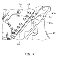
- a shim 43 can be mounted in two locations in the crosswise direction between the bottom surface of the base plate 28 and the top surface of the rear supporting portion 40 of the rear supporting frame 27 (only one is illustrated in FIG. 7 ).
- the shim 43 is used for adjusting the height of the exhaust gas post-processing device 18 and the pipe unit 23 when the base plate 28 upon which is mounted the exhaust gas post-processing device 18 is fixed to the rear supporting portion 40 of the rear supporting frame 27.
- the shim 43 is rectangular and has a pair of notches 43a that open to one side at both ends in the crosswise direction, and a through hole 43b located between the pair of notches 43a.
- the shim 43 is fixed to the top surface of the rear supporting portion 40 by a bolt 44.
- a large hole 28a with a diameter greater than the head of the bolt 44 is formed in the base plate 28 in the location where the bolt 44 is provided. Obstruction between the base plate 28 and the bolt 44 can be avoided as a result of the hole 28a. Therefore, the base plate 28 can be attached or detached with the shim 43 fixed to the rear supporting portion 40.
- the shim 43 can be prepared in various thicknesses or one or a plurality of shims 43 can be used in combination to allow the height to be adjusted.
- the exhaust gas post-processing device 18 is equipped with a diesel particulate filtering device 45, a connecting pipe 48, and a nitrogen oxide reduction catalyst device 47 in order from the exhaust gas upstream side of the engine 15 (hereinafter referred to simply as "upstream side").
- An urea aqueous solution mixing device 46 is attached to the connecting pipe 48.
- the diesel particulate filtering device 45 collects particulate matter such as soot and the like in the exhaust gas, and is mounted on the rear portion of the base plate 28 of the supporting mechanism 17.
- the urea aqueous solution mixing device 46 emits an urea aqueous solution sucked up by a pump that is not illustrated from an urea aqueous solution tank that is not illustrated, and adds the urea aqueous solution to the exhaust gas as a reducing agent.
- the added urea aqueous solution is hydrolyzed to become ammonia, and the ammonia is fed with the exhaust gas through the connecting pipe 48 to the nitrogen oxide reduction catalyst device 47.
- the ammonia from the urea aqueous solution mixing device 46 is used as the reducing agent to purify by reduction the nitrogen oxides in the exhaust gas in the nitrogen oxide reduction catalyst device 47.
- the nitrogen oxide reduction catalyst device 47 is mounted on the front portion of the base plate 28 of the supporting mechanism 17 in the same way as the diesel particulate filtering device 45.
- the diesel particulate filtering device 45 and the nitrogen oxide reduction catalyst device 47 are fixed to the base plate 28 via each of the separate attachment plates.
- the diesel particulate filtering device 45 and the nitrogen oxide reduction catalyst device 47 are disposed parallel to each other. Specifically, the diesel particulate filtering device 45 and the nitrogen oxide reduction catalyst device 47 are both cylindrical and the center axes thereof are disposed so as to extend in the crosswise direction and be parallel to each other.
- An exhaust gas inlet 45a is provided on the left edge portion of the diesel particulate filtering device 45, and an opening of the exhaust gas inlet 45a faces toward the rear.
- An exhaust gas outlet 45b is provided on the right edge portion of the diesel particulate filtering device 45, and an opening of the exhaust gas outlet 45b faces toward the front.
- An exhaust gas inlet 47a is provided on the left edge portion of the nitrogen oxide reduction catalyst device 47, and an opening of the exhaust gas inlet 47a faces toward the rear.
- An exhaust gas outlet 47b is provided on the right edge portion of the nitrogen oxide reduction catalyst device 47, and an opening of the exhaust gas outlet 47b faces toward the rear and obliquely upward.
- the connecting pipe 48 is disposed between the exhaust gas outlet 45b of the diesel particulate filtering device 45 and the exhaust gas inlet 47a of the nitrogen oxide reduction catalyst device 47.
- the connecting pipe 48 has a first bend section 48a, a linear section 48b, and a second bend section 48c, and the entire connecting pipe 48 forms an S shape.
- the first bend section 48a is located near the exhaust gas outlet 45b of the diesel particulate filtering device 45
- the second bend section 48c is located near the exhaust gas inlet 47a of the nitrogen oxide reduction catalyst device 47.
- the linear section 48b is located between the first bend section 48a and the second bend section 48c and is disposed parallel to the diesel particulate filtering device 45 and the nitrogen oxide reduction catalyst device 47.
- the urea aqueous solution mixing device 46 is provided on the first bend section 48a and emits an urea aqueous solution into the connecting pipe 48.
- the emitted urea aqueous solution becomes evenly mixed with the exhaust gas while passing through the long linear section 48b.
- the lengths in the crosswise direction of the diesel particulate filtering device 45 and the nitrogen oxide reduction catalyst device 47 are formed to be longer than the width in the crosswise direction of the base plate 28.
- FIG. 8 illustrates an enlargement of the pipe unit 23.
- the pipe unit 23 has an upstream side pipe 51 and a downstream side pipe 52.
- the upstream side pipe 51 includes a pipe body 54, and a front flange 55 and a rear flange 56 respectively provided at either end of the pipe body 54.
- Spherical joints 57 are provided between the pipe body 54 and the front and rear flanges 55, 56.
- the pipe body 54 is made of stainless steel and includes a linear extending section 54a that extends from the front toward the rear, and a bend section 54b that bends upward from the rear end portion of the extension 54a.
- Two bellows-like flexible pipe sections 54c, 54d are formed in the extending section 54a.
- the front and rear flanges 55, 56 respectively include rectangular connecting end faces 55a, 56a and pipe sections 55b, 56b that respectively extend from the connecting ends 55a, 56a.
- the connecting end face 55a of the front flange 55 is connected to an exhaust gas outlet of the turbo charger 22.
- the connecting end face 56a of the rear flange 56 is connected to the downstream side pipe 52.
- a spherical joint that uses the known technology disclosed in US Patent No. 2011/007415 may be used for example as the spherical joint 57.
- the upstream side pipe 51 is fixed to the left post 37 of the rear supporting frame 27 via a fixing plate 60 and a U-shaped metal fitting 61.
- the fixing plate 60 is L-shaped and a lower side thereof is fixed to the upper portion of the left post 37. Both ends of the U-shaped metal fitting 61 that holds the rear portion (exhaust gas downstream side) of the flexible pipe section 54d of the pipe body 54 are fixed to the standing side of the fixing plate 60 with nuts 62.
- the downstream side pipe 52 is a 90-degree elbow and includes a first pipe section 64 that is connected to the diesel particulate filtering device 45, and a second pipe section 65 that is orthogonal to the first pipe section 64.
- the second pipe section 65 is configured by the bend section 54b of the upstream side pipe 51 and a linking section that links the lower and upper sections of the connecting pipe 23.
- a flange 64a is formed at the exhaust gas downstream side end of the first pipe section 64 and is connected to the exhaust gas inlet 45a of the diesel particulate filtering device 45.
- a flange 65a is formed at the exhaust gas upstream side end of the second pipe section 65 and is connected to the connecting end face 56a of the rear flange 56 of the upstream side pipe 51.
- one or two bolt through holes H in the flange F is formed to have a larger diameter than the diameter of a coupling bolt B.
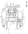
- the air cleaner 13 and a disposition thereof are explained with reference to FIGS. 2 and 11 .
- the air cleaner 13 is provided outside of the engine room and on the upper portion of the rear wheel fender 5a.
- the rear wheel fender 5a is configured of a fender front portion 5b and a fender rear portion 5c fastened to the fender front portion 5b.
- the fender front portion 5b is configured by a horizontal portion and a sloped portion that slopes forward and downward from the horizontal portion.
- the fender rear portion 5c is formed in an arced shape as seen from the side and covers the upper portion and the upper rear portion of the rear wheel 5.
- the air cleaner 13 is mounted on the horizontal portion of the fender front portion 5b.
- FIG. 11 is a plan view of the air cleaner 13 and portions related to the air cleaner 13 with the vehicle body cover 9 and the air cleaner cover 70 removed.
- the air cleaner 13 is cylindrical and a cap 71 that covers an air intake mouth 13a is provided on the upper portion of the air cleaner 13, and an openable and closable lid 13b is provided on the front portion of the air cleaner 13.
- a filter 72 is provided in an attachable and detachable manner inside the air cleaner 13.
- the air cleaner cover 70 covers most of the air cleaner 13 excluding the front end portion to which the air intake mouth 13a, the cap 71, and the lid 13b are attached.
- the filter 72 can be maintained and exchanged by opening the lid 13b and pulling the filter 72 out obliquely toward the front.
- the air cleaner 13 is disposed on the upper portion of the fender front portion 5b of the rear wheel fender 5a and the lateral side of the rear of the cab 6. More specifically, the front portion of the air cleaner 13 is located to the rear of the steps 10 and beside the rear end portion of the cab 6, and the rear portion of the air cleaner 13 is located beside the front portion of the operating fluid tank 19.
- a center axis C of the air cleaner 13 is substantially horizontal and is slanted with respect to a center axis extending to the front and rear of the vehicle so that the front portion of the air cleaner 13 is further away from the cab 6 than the rear portion.
- the filter 72 can be pulled out toward the front along the center axis C.
- the stopper 12 is provided on the cab 6 to limit the maximum opening degree of the door 11, and as illustrated in FIG. 12 , the front end portion of the air cleaner 13 is disposed in a location that does not obstruct the door 11 even if the door 11 is opened to the maximum to abut the stopper 12.
- the operator can stand on the steps 10 and open the lid 13b of the air cleaner 13 to easily perform maintenance or exchange the filter 72 as illustrated in FIG. 12 .
- air is introduced from the air cleaner 13 and fed into the engine 15 through the intake pipe 24 and the turbo charger 22.
- Exhaust gas from the engine 15 is introduced through the pipe unit 23 into the exhaust gas post-processing device 18 after driving the turbo charger 22.
- Particulate matter such as soot is collected by the diesel particulate filtering device 45 in the exhaust gas post-processing device 18.
- the particulate matter is introduced into the urea aqueous solution mixing device 46.
- An urea aqueous solution is emitted into the exhaust gas to mix with the exhaust gas in the urea aqueous solution mixing device 46. Consequently, the urea aqueous solution is hydrolyzed by the heat of the exhaust gas and water vapor in the exhaust gas to become ammonia.
- the ammonia generated in this way is fed with the exhaust gas through the connecting pipe 48 to the nitrogen oxide reduction catalyst device 47.
- the ammonia is used as the reducing agent to purify by reduction the nitrogen oxides in the exhaust gas in the nitrogen oxide reduction catalyst device 47.
- the diesel particulate filtering device 45 is desirably removed from the vehicle at certain time periods for maintenance. Accordingly, the exhaust gas post-processing device 18 is made into a sub-unit with the base plate 28 to facilitate assembly and maintenance of the exhaust gas post-processing device 18. When assembling the sub-unit onto the supporting mechanism 17, the pipe unit 23 is fixed to the engine 15 and the supporting mechanism 17.
- the front flange 55 of the upstream side pipe 51 is connected to the exhaust gas outlet of the turbo charger 22, and the downstream side of the flexible pipe 54d of the pipe body 54 is fixed to the supporting mechanism 17 with the fixing plate 60 and the U-shaped metal fitting 61.
- the upstream side pipe 51 and the spherical joint 57 on the exhaust gas upstream side are connected temporarily.
- the U-shaped metal fitting 61 is also fastened temporarily.
- the downstream side pipe 52 is connected to the upstream side pipe 51.
- the upstream side pipe 51 and the downstream side pipe 52 may be connected to each other before coupling the upstream side pipe 51 to the turbo charger 22.
- the flanges 56 and 65a are connected to each other with the exhaust gas downstream side spherical joint 57 in a temporarily fastened state.
- the sub-unit is supported by the supporting mechanism 17 in a state in which the pipe unit 23 is fixed to the engine 15 and the supporting mechanism 17 side.
- both the heights thereof are adjusted by the shim 43 and adjustment in the front-rear, vertical, and crosswise directions are performed by adjusting the assembly of the flanges 64a, 65a at both ends of the downstream side pipe 52.
- angle adjustment of the sub-unit and the supporting mechanism 17 is performed with the spherical joints 57 at either end of the upstream side pipe 51.
- the shim adjustments are rarely performed during maintenance since the adjustments are performed by the manufacturer before shipping.
- the engine 15 and the transmission 20 are mounted on the vehicle body frame 2 via the rubber mounts 21, and the exhaust gas post-processing device 18 is mounted directly onto the vehicle body frame 2 via the supporting mechanism 17.
- the exhaust gas post-processing device 18 is mounted directly onto the vehicle body frame 2 via the supporting mechanism 17.
- the difference between the two vibrations can be sufficiently absorbed since the relatively long flexible pipe sections 54c, 54d are formed in the extending section 54a of the pipe unit 23. Therefore, the vibration of the engine 15 can be suppressed.
- Exchanging and cleaning of the filter 72 are desirably performed at certain time periods in the air cleaner 13. At this time the filter 72 is desirably removed from the air cleaner 13.
- the operator When removing the filter 72 from the air cleaner 13, the operator stands on the steps 10 and opens the lid 13b of the air cleaner 13 as illustrated in FIG. 13.
- the filter 72 of the air cleaner 13 may be pulled out toward the front along the center axis C of the air cleaner 13. At this time, since the air cleaner 13 is slanted so that the front side thereof is further away from the cab 6 than the rear side thereof, the work to remove the filter 72 is easy to perform.
- a reduction in visibility to the rear is prevented and maintenance work on the air cleaner can be performed more easily in the wheel loader of the present invention since the air cleaner is disposed toward the rear portion of the cab and is disposed in a slanted manner so that the front from where the filter is pulled out is further away from the cab.
Landscapes
- Engineering & Computer Science (AREA)
- General Engineering & Computer Science (AREA)
- Mining & Mineral Resources (AREA)
- Civil Engineering (AREA)
- Structural Engineering (AREA)
- Chemical & Material Sciences (AREA)
- Combustion & Propulsion (AREA)
- Mechanical Engineering (AREA)
- Transportation (AREA)
- Exhaust Gas After Treatment (AREA)
- Processes For Solid Components From Exhaust (AREA)
- Cooling, Air Intake And Gas Exhaust, And Fuel Tank Arrangements In Propulsion Units (AREA)
Claims (7)
- Chargeuse sur roues (1) comprenant :une cabine (6) avec un siège de conducteur prévu à l'intérieur ;des marches (10) prévues à côté de la cabine (6) pour monter à la cabine (6) et pour descendre de celle-ci ;un moteur (15) disposé à l'arrière de la cabine (6) ;un couvercle de corps de véhicule (9) qui couvre le moteur (15) ; etun purificateur d'air (13) ayant à l'intérieur un filtre (72) qui peut être échangé en le tirant horizontalement, le purificateur d'air (13) étant connecté au moteur (15) via un tube d'admission (24), le purificateur d'air (13) étant disposé de manière inclinée de telle façon qu'un côté avant du purificateur d'air (13) depuis lequel le filtre (45) peut être tiré est plus éloigné de la cabine (6) qu'un côté arrière opposé ;caractérisée en ce quele purificateur d'air (13) est disposé à l'extérieur du couvercle de corps de véhicule (9), à côté et à l'arrière de la cabine (6), et en arrière des marches (10), de telle façon que le filtre (72) peut être extrait en le tirant vers les marches (10).
- Chargeuse sur roues (1) selon la revendication 1, caractérisée en ce que
la cabine (6) comprend un corps de cabine (6b) et une porte (11) supportée par une portion arrière du corps de cabine (6b) de sorte que le côté avant de la porte (11) est susceptible d'être ouvert et fermé ; et
le purificateur d'air (13) est disposé à un emplacement qui n'obstrue pas la porte (11) quand la porte (11) est totalement ouverte. - Chargeuse sur roues (1) selon l'une quelconque des revendications 1 et 2, caractérisée par
un réservoir pour fluide de travail (19) disposé entre la cabine (6) et le moteur (15) ; dans laquelle
le purificateur d'air (13) est disposé à côté du réservoir pour fluide de travail (19). - Chargeuse sur roues (1) selon l'une quelconque des revendications 1 à 3, caractérisée par
un garde-boue de roue arrière (5a) disposé au-dessus de la roue arrière (5), et dans laquelle
le purificateur d'air (13) est fixé sur une portion supérieure du garde-boue de roue arrière (5a). - Chargeuse sur roues (1) selon l'une quelconque des revendications 1 à 4, caractérisée par
un dispositif de post-traitement des gaz d'échappement (18) qui est disposé au-dessus du moteur (15) et qui inclut un dispositif de filtration de particules diesel (45) et un dispositif catalyseur par réduction d'oxydes azotés (47), qui sont disposés dans une rangée dans la direction avant/arrière. - Chargeuse sur roues (1) selon la revendication 5, caractérisée par
un châssis de corps de véhicule (2) qui supporte le moteur (15) ; et
un mécanisme de support (17) qui est fixé au châssis de corps de véhicule (2) est sur lequel est monté le dispositif de post-traitement des gaz d'échappement (18). - Chargeuse sur roues (1) selon l'une quelconque des revendications 1 à 6, caractérisée par
un couvercle de purificateur d'air (70) qui couvre des portions à l'exception d'une ouverture d'extraction pour le filtre (72) et une embouchure d'admission d'air (13a).
Applications Claiming Priority (2)
| Application Number | Priority Date | Filing Date | Title |
|---|---|---|---|
| JP2012237063 | 2012-10-26 | ||
| PCT/JP2012/082114 WO2014064852A1 (fr) | 2012-10-26 | 2012-12-12 | Chargeuse à pneus |
Publications (3)
| Publication Number | Publication Date |
|---|---|
| EP2746464A1 EP2746464A1 (fr) | 2014-06-25 |
| EP2746464A4 EP2746464A4 (fr) | 2014-06-25 |
| EP2746464B1 true EP2746464B1 (fr) | 2015-03-04 |
Family
ID=49639688
Family Applications (1)
| Application Number | Title | Priority Date | Filing Date |
|---|---|---|---|
| EP12867723.4A Not-in-force EP2746464B1 (fr) | 2012-10-26 | 2012-12-12 | Chargeuse à pneus |
Country Status (4)
| Country | Link |
|---|---|
| US (1) | US9353502B2 (fr) |
| EP (1) | EP2746464B1 (fr) |
| CN (1) | CN103906878B (fr) |
| WO (1) | WO2014064852A1 (fr) |
Families Citing this family (14)
| Publication number | Priority date | Publication date | Assignee | Title |
|---|---|---|---|---|
| JP6178149B2 (ja) * | 2013-07-24 | 2017-08-09 | ヤンマー株式会社 | トラクター |
| JP6297905B2 (ja) * | 2014-04-22 | 2018-03-20 | 日立建機株式会社 | 建設機械 |
| CN104364140B (zh) * | 2014-06-30 | 2016-10-12 | 株式会社小松制作所 | 作业车辆 |
| US9487079B2 (en) * | 2014-08-11 | 2016-11-08 | Deere & Company | Air inlet and cleaner arrangement for work vehicle |
| EP2985166B1 (fr) * | 2014-08-14 | 2017-08-02 | CNH Industrial Italia S.p.A. | Système d'échappement pour véhicule tout-terrain |
| US9267267B1 (en) | 2014-09-04 | 2016-02-23 | Komatsu Ltd. | Wheel loader |
| EP2955280B1 (fr) * | 2015-03-10 | 2017-10-25 | Komatsu Ltd. | Véhicule industriel |
| CN105035175B (zh) * | 2015-07-30 | 2018-12-07 | 广西柳工机械股份有限公司 | 应用于lng装载机上的加液装置 |
| JP6653373B2 (ja) * | 2016-03-16 | 2020-02-26 | 株式会社小松製作所 | ダンプトラック |
| WO2016163300A1 (fr) * | 2016-03-31 | 2016-10-13 | 株式会社小松製作所 | Camion-benne |
| CN107558526B (zh) * | 2017-10-31 | 2023-08-18 | 三一重机有限公司 | 可调位置钢管管夹支架及液压挖掘机 |
| CN107905922A (zh) * | 2017-11-30 | 2018-04-13 | 安徽铜冠机械股份有限公司 | 井下运输车辆前置式发动机进排气系统 |
| CN109184890B (zh) * | 2018-08-31 | 2020-07-21 | 广西柳工机械股份有限公司 | 装载机发动机后处理系统 |
| JP7649200B2 (ja) * | 2021-06-04 | 2025-03-19 | 日立建機株式会社 | 作業機械 |
Family Cites Families (23)
| Publication number | Priority date | Publication date | Assignee | Title |
|---|---|---|---|---|
| US3720279A (en) * | 1971-02-17 | 1973-03-13 | Euclid | Combustion air intake system for an off-the-road vehicle |
| US4917202A (en) * | 1988-12-19 | 1990-04-17 | Caterpillar Inc. | Air inlet deflector assembly for an air cleaner |
| JP2003011679A (ja) | 2001-06-27 | 2003-01-15 | Shin Caterpillar Mitsubishi Ltd | 建設機械の冷却装置 |
| JP4090019B2 (ja) | 2002-05-17 | 2008-05-28 | 株式会社小松製作所 | 分割組立容易な車両構成 |
| US6874589B1 (en) * | 2002-12-16 | 2005-04-05 | Crane Carrier Company | Deck mounted air cleaner assembly for vehicle |
| CN100482901C (zh) * | 2004-03-29 | 2009-04-29 | 株式会社久保田 | 具有旋转台的旋转作业机 |
| EP1832731B1 (fr) * | 2004-12-27 | 2018-08-15 | Kobelco Construction Machinery Co., Ltd. | Structure de refroidissement d'equipement de construction |
| JP4270239B2 (ja) * | 2006-08-11 | 2009-05-27 | コベルコ建機株式会社 | 建設機械 |
| US7717205B2 (en) * | 2006-11-28 | 2010-05-18 | Caterpillar Inc. | Engine hood assembly enclosure with exhaust aftertreatment device integrated therein, and machine using same |
| JP4501945B2 (ja) * | 2007-02-23 | 2010-07-14 | コベルコ建機株式会社 | 建設機械の冷却器用フィルタの取付構造 |
| US7836967B2 (en) * | 2008-07-28 | 2010-11-23 | Caterpillar Inc | Cooling system packaging arrangement for a machine |
| JP4724241B2 (ja) | 2009-07-09 | 2011-07-13 | 株式会社東芝 | ディスク記憶装置及びデータ検出方法 |
| JP5325081B2 (ja) * | 2009-12-07 | 2013-10-23 | 株式会社クボタ | 作業車 |
| JP5033226B2 (ja) * | 2010-08-02 | 2012-09-26 | 株式会社小松製作所 | 作業車両 |
| JP5641984B2 (ja) * | 2011-03-07 | 2014-12-17 | 日立建機株式会社 | 作業機械 |
| CN202055274U (zh) * | 2011-05-08 | 2011-11-30 | 煤炭科学研究总院太原研究院 | 多功能铲运机 |
| JP5508351B2 (ja) * | 2011-06-30 | 2014-05-28 | 日立建機株式会社 | 作業機械 |
| JP5510466B2 (ja) * | 2012-01-10 | 2014-06-04 | コベルコ建機株式会社 | 建設機械 |
| CN103890277B (zh) * | 2012-10-26 | 2015-06-10 | 株式会社小松制作所 | 轮式装载机 |
| WO2014064853A1 (fr) * | 2012-10-26 | 2014-05-01 | 株式会社小松製作所 | Véhicule de travail |
| EP2792795B1 (fr) * | 2013-02-22 | 2015-04-08 | Komatsu Ltd. | Chargeur à roues |
| JP5867485B2 (ja) * | 2013-11-20 | 2016-02-24 | コベルコ建機株式会社 | 建設機械 |
| US9267267B1 (en) * | 2014-09-04 | 2016-02-23 | Komatsu Ltd. | Wheel loader |
-
2012
- 2012-12-12 EP EP12867723.4A patent/EP2746464B1/fr not_active Not-in-force
- 2012-12-12 WO PCT/JP2012/082114 patent/WO2014064852A1/fr not_active Ceased
- 2012-12-12 CN CN201280014914.2A patent/CN103906878B/zh not_active Expired - Fee Related
- 2012-12-12 US US14/001,353 patent/US9353502B2/en active Active
Also Published As
| Publication number | Publication date |
|---|---|
| US9353502B2 (en) | 2016-05-31 |
| CN103906878A (zh) | 2014-07-02 |
| EP2746464A1 (fr) | 2014-06-25 |
| CN103906878B (zh) | 2015-06-24 |
| US20150299981A1 (en) | 2015-10-22 |
| EP2746464A4 (fr) | 2014-06-25 |
| WO2014064852A1 (fr) | 2014-05-01 |
Similar Documents
| Publication | Publication Date | Title |
|---|---|---|
| EP2746464B1 (fr) | Chargeuse à pneus | |
| EP2743472B1 (fr) | Véhicule de travail | |
| EP2762644B1 (fr) | Chargeuse montée sur roues | |
| EP2728075B1 (fr) | Machine de terrassement | |
| JP4705130B2 (ja) | 建設機械 | |
| CN104520551B (zh) | 支撑机构、排气处理单元及轮式装载机 | |
| US9657456B2 (en) | Wheel loader | |
| EP2853429B1 (fr) | Mécanisme de support, unité de traitement de gaz d'échappement, chargeuse montée sur roues | |
| US9169619B2 (en) | Wheel loader | |
| JP5363681B1 (ja) | 作業車両 | |
| US9657459B2 (en) | Construction machine | |
| JP5325357B1 (ja) | ホイールローダ |
Legal Events
| Date | Code | Title | Description |
|---|---|---|---|
| PUAI | Public reference made under article 153(3) epc to a published international application that has entered the european phase |
Free format text: ORIGINAL CODE: 0009012 |
|
| 17P | Request for examination filed |
Effective date: 20130812 |
|
| A4 | Supplementary search report drawn up and despatched |
Effective date: 20140327 |
|
| AK | Designated contracting states |
Kind code of ref document: A1 Designated state(s): AL AT BE BG CH CY CZ DE DK EE ES FI FR GB GR HR HU IE IS IT LI LT LU LV MC MK MT NL NO PL PT RO RS SE SI SK SM TR |
|
| GRAP | Despatch of communication of intention to grant a patent |
Free format text: ORIGINAL CODE: EPIDOSNIGR1 |
|
| RIC1 | Information provided on ipc code assigned before grant |
Ipc: E02F 9/08 20060101ALI20141016BHEP Ipc: E02F 9/00 20060101AFI20141016BHEP |
|
| DAX | Request for extension of the european patent (deleted) | ||
| INTG | Intention to grant announced |
Effective date: 20141105 |
|
| GRAS | Grant fee paid |
Free format text: ORIGINAL CODE: EPIDOSNIGR3 |
|
| GRAA | (expected) grant |
Free format text: ORIGINAL CODE: 0009210 |
|
| AK | Designated contracting states |
Kind code of ref document: B1 Designated state(s): AL AT BE BG CH CY CZ DE DK EE ES FI FR GB GR HR HU IE IS IT LI LT LU LV MC MK MT NL NO PL PT RO RS SE SI SK SM TR |
|
| REG | Reference to a national code |
Ref country code: GB Ref legal event code: FG4D |
|
| REG | Reference to a national code |
Ref country code: CH Ref legal event code: EP |
|
| REG | Reference to a national code |
Ref country code: IE Ref legal event code: FG4D |
|
| REG | Reference to a national code |
Ref country code: SE Ref legal event code: TRGR |
|
| REG | Reference to a national code |
Ref country code: AT Ref legal event code: REF Ref document number: 714047 Country of ref document: AT Kind code of ref document: T Effective date: 20150415 |
|
| REG | Reference to a national code |
Ref country code: DE Ref legal event code: R096 Ref document number: 602012005742 Country of ref document: DE Effective date: 20150416 |
|
| REG | Reference to a national code |
Ref country code: AT Ref legal event code: MK05 Ref document number: 714047 Country of ref document: AT Kind code of ref document: T Effective date: 20150304 Ref country code: NL Ref legal event code: VDEP Effective date: 20150304 |
|
| PG25 | Lapsed in a contracting state [announced via postgrant information from national office to epo] |
Ref country code: FI Free format text: LAPSE BECAUSE OF FAILURE TO SUBMIT A TRANSLATION OF THE DESCRIPTION OR TO PAY THE FEE WITHIN THE PRESCRIBED TIME-LIMIT Effective date: 20150304 Ref country code: NO Free format text: LAPSE BECAUSE OF FAILURE TO SUBMIT A TRANSLATION OF THE DESCRIPTION OR TO PAY THE FEE WITHIN THE PRESCRIBED TIME-LIMIT Effective date: 20150604 Ref country code: LT Free format text: LAPSE BECAUSE OF FAILURE TO SUBMIT A TRANSLATION OF THE DESCRIPTION OR TO PAY THE FEE WITHIN THE PRESCRIBED TIME-LIMIT Effective date: 20150304 Ref country code: ES Free format text: LAPSE BECAUSE OF FAILURE TO SUBMIT A TRANSLATION OF THE DESCRIPTION OR TO PAY THE FEE WITHIN THE PRESCRIBED TIME-LIMIT Effective date: 20150304 Ref country code: HR Free format text: LAPSE BECAUSE OF FAILURE TO SUBMIT A TRANSLATION OF THE DESCRIPTION OR TO PAY THE FEE WITHIN THE PRESCRIBED TIME-LIMIT Effective date: 20150304 |
|
| REG | Reference to a national code |
Ref country code: LT Ref legal event code: MG4D |
|
| PG25 | Lapsed in a contracting state [announced via postgrant information from national office to epo] |
Ref country code: LV Free format text: LAPSE BECAUSE OF FAILURE TO SUBMIT A TRANSLATION OF THE DESCRIPTION OR TO PAY THE FEE WITHIN THE PRESCRIBED TIME-LIMIT Effective date: 20150304 Ref country code: RS Free format text: LAPSE BECAUSE OF FAILURE TO SUBMIT A TRANSLATION OF THE DESCRIPTION OR TO PAY THE FEE WITHIN THE PRESCRIBED TIME-LIMIT Effective date: 20150304 Ref country code: AT Free format text: LAPSE BECAUSE OF FAILURE TO SUBMIT A TRANSLATION OF THE DESCRIPTION OR TO PAY THE FEE WITHIN THE PRESCRIBED TIME-LIMIT Effective date: 20150304 Ref country code: GR Free format text: LAPSE BECAUSE OF FAILURE TO SUBMIT A TRANSLATION OF THE DESCRIPTION OR TO PAY THE FEE WITHIN THE PRESCRIBED TIME-LIMIT Effective date: 20150605 |
|
| PG25 | Lapsed in a contracting state [announced via postgrant information from national office to epo] |
Ref country code: NL Free format text: LAPSE BECAUSE OF FAILURE TO SUBMIT A TRANSLATION OF THE DESCRIPTION OR TO PAY THE FEE WITHIN THE PRESCRIBED TIME-LIMIT Effective date: 20150304 |
|
| PG25 | Lapsed in a contracting state [announced via postgrant information from national office to epo] |
Ref country code: RO Free format text: LAPSE BECAUSE OF FAILURE TO SUBMIT A TRANSLATION OF THE DESCRIPTION OR TO PAY THE FEE WITHIN THE PRESCRIBED TIME-LIMIT Effective date: 20150304 Ref country code: SK Free format text: LAPSE BECAUSE OF FAILURE TO SUBMIT A TRANSLATION OF THE DESCRIPTION OR TO PAY THE FEE WITHIN THE PRESCRIBED TIME-LIMIT Effective date: 20150304 Ref country code: PT Free format text: LAPSE BECAUSE OF FAILURE TO SUBMIT A TRANSLATION OF THE DESCRIPTION OR TO PAY THE FEE WITHIN THE PRESCRIBED TIME-LIMIT Effective date: 20150706 Ref country code: CZ Free format text: LAPSE BECAUSE OF FAILURE TO SUBMIT A TRANSLATION OF THE DESCRIPTION OR TO PAY THE FEE WITHIN THE PRESCRIBED TIME-LIMIT Effective date: 20150304 Ref country code: EE Free format text: LAPSE BECAUSE OF FAILURE TO SUBMIT A TRANSLATION OF THE DESCRIPTION OR TO PAY THE FEE WITHIN THE PRESCRIBED TIME-LIMIT Effective date: 20150304 |
|
| PG25 | Lapsed in a contracting state [announced via postgrant information from national office to epo] |
Ref country code: IS Free format text: LAPSE BECAUSE OF FAILURE TO SUBMIT A TRANSLATION OF THE DESCRIPTION OR TO PAY THE FEE WITHIN THE PRESCRIBED TIME-LIMIT Effective date: 20150704 Ref country code: PL Free format text: LAPSE BECAUSE OF FAILURE TO SUBMIT A TRANSLATION OF THE DESCRIPTION OR TO PAY THE FEE WITHIN THE PRESCRIBED TIME-LIMIT Effective date: 20150304 |
|
| REG | Reference to a national code |
Ref country code: DE Ref legal event code: R097 Ref document number: 602012005742 Country of ref document: DE |
|
| PG25 | Lapsed in a contracting state [announced via postgrant information from national office to epo] |
Ref country code: IT Free format text: LAPSE BECAUSE OF FAILURE TO SUBMIT A TRANSLATION OF THE DESCRIPTION OR TO PAY THE FEE WITHIN THE PRESCRIBED TIME-LIMIT Effective date: 20150304 |
|
| PLBE | No opposition filed within time limit |
Free format text: ORIGINAL CODE: 0009261 |
|
| STAA | Information on the status of an ep patent application or granted ep patent |
Free format text: STATUS: NO OPPOSITION FILED WITHIN TIME LIMIT |
|
| PG25 | Lapsed in a contracting state [announced via postgrant information from national office to epo] |
Ref country code: DK Free format text: LAPSE BECAUSE OF FAILURE TO SUBMIT A TRANSLATION OF THE DESCRIPTION OR TO PAY THE FEE WITHIN THE PRESCRIBED TIME-LIMIT Effective date: 20150304 |
|
| 26N | No opposition filed |
Effective date: 20151207 |
|
| PG25 | Lapsed in a contracting state [announced via postgrant information from national office to epo] |
Ref country code: SI Free format text: LAPSE BECAUSE OF FAILURE TO SUBMIT A TRANSLATION OF THE DESCRIPTION OR TO PAY THE FEE WITHIN THE PRESCRIBED TIME-LIMIT Effective date: 20150304 |
|
| PG25 | Lapsed in a contracting state [announced via postgrant information from national office to epo] |
Ref country code: BE Free format text: LAPSE BECAUSE OF NON-PAYMENT OF DUE FEES Effective date: 20151231 |
|
| PG25 | Lapsed in a contracting state [announced via postgrant information from national office to epo] |
Ref country code: MC Free format text: LAPSE BECAUSE OF FAILURE TO SUBMIT A TRANSLATION OF THE DESCRIPTION OR TO PAY THE FEE WITHIN THE PRESCRIBED TIME-LIMIT Effective date: 20150304 Ref country code: LU Free format text: LAPSE BECAUSE OF FAILURE TO SUBMIT A TRANSLATION OF THE DESCRIPTION OR TO PAY THE FEE WITHIN THE PRESCRIBED TIME-LIMIT Effective date: 20151212 |
|
| REG | Reference to a national code |
Ref country code: CH Ref legal event code: PL |
|
| PG25 | Lapsed in a contracting state [announced via postgrant information from national office to epo] |
Ref country code: BE Free format text: LAPSE BECAUSE OF FAILURE TO SUBMIT A TRANSLATION OF THE DESCRIPTION OR TO PAY THE FEE WITHIN THE PRESCRIBED TIME-LIMIT Effective date: 20150304 |
|
| REG | Reference to a national code |
Ref country code: IE Ref legal event code: MM4A |
|
| REG | Reference to a national code |
Ref country code: FR Ref legal event code: ST Effective date: 20160831 |
|
| PG25 | Lapsed in a contracting state [announced via postgrant information from national office to epo] |
Ref country code: IE Free format text: LAPSE BECAUSE OF NON-PAYMENT OF DUE FEES Effective date: 20151212 Ref country code: CH Free format text: LAPSE BECAUSE OF NON-PAYMENT OF DUE FEES Effective date: 20151231 Ref country code: LI Free format text: LAPSE BECAUSE OF NON-PAYMENT OF DUE FEES Effective date: 20151231 |
|
| PG25 | Lapsed in a contracting state [announced via postgrant information from national office to epo] |
Ref country code: FR Free format text: LAPSE BECAUSE OF NON-PAYMENT OF DUE FEES Effective date: 20151231 |
|
| PG25 | Lapsed in a contracting state [announced via postgrant information from national office to epo] |
Ref country code: HU Free format text: LAPSE BECAUSE OF FAILURE TO SUBMIT A TRANSLATION OF THE DESCRIPTION OR TO PAY THE FEE WITHIN THE PRESCRIBED TIME-LIMIT; INVALID AB INITIO Effective date: 20121212 Ref country code: BG Free format text: LAPSE BECAUSE OF FAILURE TO SUBMIT A TRANSLATION OF THE DESCRIPTION OR TO PAY THE FEE WITHIN THE PRESCRIBED TIME-LIMIT Effective date: 20150304 Ref country code: SM Free format text: LAPSE BECAUSE OF FAILURE TO SUBMIT A TRANSLATION OF THE DESCRIPTION OR TO PAY THE FEE WITHIN THE PRESCRIBED TIME-LIMIT Effective date: 20150304 |
|
| PG25 | Lapsed in a contracting state [announced via postgrant information from national office to epo] |
Ref country code: CY Free format text: LAPSE BECAUSE OF FAILURE TO SUBMIT A TRANSLATION OF THE DESCRIPTION OR TO PAY THE FEE WITHIN THE PRESCRIBED TIME-LIMIT Effective date: 20150304 |
|
| GBPC | Gb: european patent ceased through non-payment of renewal fee |
Effective date: 20161212 |
|
| PG25 | Lapsed in a contracting state [announced via postgrant information from national office to epo] |
Ref country code: MT Free format text: LAPSE BECAUSE OF FAILURE TO SUBMIT A TRANSLATION OF THE DESCRIPTION OR TO PAY THE FEE WITHIN THE PRESCRIBED TIME-LIMIT Effective date: 20150304 |
|
| PG25 | Lapsed in a contracting state [announced via postgrant information from national office to epo] |
Ref country code: GB Free format text: LAPSE BECAUSE OF NON-PAYMENT OF DUE FEES Effective date: 20161212 |
|
| PG25 | Lapsed in a contracting state [announced via postgrant information from national office to epo] |
Ref country code: MK Free format text: LAPSE BECAUSE OF FAILURE TO SUBMIT A TRANSLATION OF THE DESCRIPTION OR TO PAY THE FEE WITHIN THE PRESCRIBED TIME-LIMIT Effective date: 20150304 |
|
| PG25 | Lapsed in a contracting state [announced via postgrant information from national office to epo] |
Ref country code: AL Free format text: LAPSE BECAUSE OF FAILURE TO SUBMIT A TRANSLATION OF THE DESCRIPTION OR TO PAY THE FEE WITHIN THE PRESCRIBED TIME-LIMIT Effective date: 20150304 Ref country code: TR Free format text: LAPSE BECAUSE OF FAILURE TO SUBMIT A TRANSLATION OF THE DESCRIPTION OR TO PAY THE FEE WITHIN THE PRESCRIBED TIME-LIMIT Effective date: 20150304 |
|
| PGFP | Annual fee paid to national office [announced via postgrant information from national office to epo] |
Ref country code: SE Payment date: 20231110 Year of fee payment: 12 Ref country code: DE Payment date: 20231031 Year of fee payment: 12 |
|
| REG | Reference to a national code |
Ref country code: DE Ref legal event code: R119 Ref document number: 602012005742 Country of ref document: DE |
|
| REG | Reference to a national code |
Ref country code: SE Ref legal event code: EUG |
|
| PG25 | Lapsed in a contracting state [announced via postgrant information from national office to epo] |
Ref country code: DE Free format text: LAPSE BECAUSE OF NON-PAYMENT OF DUE FEES Effective date: 20250701 |