EP2746509B1 - Dämpfvorrichtung für eine Scharnieranordnung - Google Patents
Dämpfvorrichtung für eine Scharnieranordnung Download PDFInfo
- Publication number
- EP2746509B1 EP2746509B1 EP12198584.0A EP12198584A EP2746509B1 EP 2746509 B1 EP2746509 B1 EP 2746509B1 EP 12198584 A EP12198584 A EP 12198584A EP 2746509 B1 EP2746509 B1 EP 2746509B1
- Authority
- EP
- European Patent Office
- Prior art keywords
- adjustment member
- maintaining member
- housing
- hinge assembly
- maintaining
- Prior art date
- Legal status (The legal status is an assumption and is not a legal conclusion. Google has not performed a legal analysis and makes no representation as to the accuracy of the status listed.)
- Active
Links
Images






Classifications
-
- E—FIXED CONSTRUCTIONS
- E05—LOCKS; KEYS; WINDOW OR DOOR FITTINGS; SAFES
- E05F—DEVICES FOR MOVING WINGS INTO OPEN OR CLOSED POSITION; CHECKS FOR WINGS; WING FITTINGS NOT OTHERWISE PROVIDED FOR, CONCERNED WITH THE FUNCTIONING OF THE WING
- E05F5/00—Braking devices, e.g. checks; Stops; Buffers
- E05F5/006—Braking devices, e.g. checks; Stops; Buffers for hinges having a cup-shaped fixing part, e.g. for attachment to cabinets or furniture
-
- E—FIXED CONSTRUCTIONS
- E05—LOCKS; KEYS; WINDOW OR DOOR FITTINGS; SAFES
- E05F—DEVICES FOR MOVING WINGS INTO OPEN OR CLOSED POSITION; CHECKS FOR WINGS; WING FITTINGS NOT OTHERWISE PROVIDED FOR, CONCERNED WITH THE FUNCTIONING OF THE WING
- E05F5/00—Braking devices, e.g. checks; Stops; Buffers
- E05F5/02—Braking devices, e.g. checks; Stops; Buffers specially for preventing the slamming of swinging wings during final closing movement, e.g. jamb stops
-
- E—FIXED CONSTRUCTIONS
- E05—LOCKS; KEYS; WINDOW OR DOOR FITTINGS; SAFES
- E05F—DEVICES FOR MOVING WINGS INTO OPEN OR CLOSED POSITION; CHECKS FOR WINGS; WING FITTINGS NOT OTHERWISE PROVIDED FOR, CONCERNED WITH THE FUNCTIONING OF THE WING
- E05F5/00—Braking devices, e.g. checks; Stops; Buffers
- E05F5/02—Braking devices, e.g. checks; Stops; Buffers specially for preventing the slamming of swinging wings during final closing movement, e.g. jamb stops
- E05F5/04—Braking devices, e.g. checks; Stops; Buffers specially for preventing the slamming of swinging wings during final closing movement, e.g. jamb stops hand-operated, e.g. removable; operated by centrifugal action or by high closing speed
-
- E—FIXED CONSTRUCTIONS
- E05—LOCKS; KEYS; WINDOW OR DOOR FITTINGS; SAFES
- E05F—DEVICES FOR MOVING WINGS INTO OPEN OR CLOSED POSITION; CHECKS FOR WINGS; WING FITTINGS NOT OTHERWISE PROVIDED FOR, CONCERNED WITH THE FUNCTIONING OF THE WING
- E05F5/00—Braking devices, e.g. checks; Stops; Buffers
- E05F5/02—Braking devices, e.g. checks; Stops; Buffers specially for preventing the slamming of swinging wings during final closing movement, e.g. jamb stops
- E05F5/04—Braking devices, e.g. checks; Stops; Buffers specially for preventing the slamming of swinging wings during final closing movement, e.g. jamb stops hand-operated, e.g. removable; operated by centrifugal action or by high closing speed
- E05F2005/046—Braking devices, e.g. checks; Stops; Buffers specially for preventing the slamming of swinging wings during final closing movement, e.g. jamb stops hand-operated, e.g. removable; operated by centrifugal action or by high closing speed hand operated
-
- E—FIXED CONSTRUCTIONS
- E05—LOCKS; KEYS; WINDOW OR DOOR FITTINGS; SAFES
- E05Y—INDEXING SCHEME ASSOCIATED WITH SUBCLASSES E05D AND E05F, RELATING TO CONSTRUCTION ELEMENTS, ELECTRIC CONTROL, POWER SUPPLY, POWER SIGNAL OR TRANSMISSION, USER INTERFACES, MOUNTING OR COUPLING, DETAILS, ACCESSORIES, AUXILIARY OPERATIONS NOT OTHERWISE PROVIDED FOR, APPLICATION THEREOF
- E05Y2201/00—Constructional elements; Accessories therefor
- E05Y2201/20—Brakes; Disengaging means; Holders; Stops; Valves; Accessories therefor
- E05Y2201/21—Brakes
-
- E—FIXED CONSTRUCTIONS
- E05—LOCKS; KEYS; WINDOW OR DOOR FITTINGS; SAFES
- E05Y—INDEXING SCHEME ASSOCIATED WITH SUBCLASSES E05D AND E05F, RELATING TO CONSTRUCTION ELEMENTS, ELECTRIC CONTROL, POWER SUPPLY, POWER SIGNAL OR TRANSMISSION, USER INTERFACES, MOUNTING OR COUPLING, DETAILS, ACCESSORIES, AUXILIARY OPERATIONS NOT OTHERWISE PROVIDED FOR, APPLICATION THEREOF
- E05Y2201/00—Constructional elements; Accessories therefor
- E05Y2201/20—Brakes; Disengaging means; Holders; Stops; Valves; Accessories therefor
- E05Y2201/218—Holders
- E05Y2201/22—Locks
-
- E—FIXED CONSTRUCTIONS
- E05—LOCKS; KEYS; WINDOW OR DOOR FITTINGS; SAFES
- E05Y—INDEXING SCHEME ASSOCIATED WITH SUBCLASSES E05D AND E05F, RELATING TO CONSTRUCTION ELEMENTS, ELECTRIC CONTROL, POWER SUPPLY, POWER SIGNAL OR TRANSMISSION, USER INTERFACES, MOUNTING OR COUPLING, DETAILS, ACCESSORIES, AUXILIARY OPERATIONS NOT OTHERWISE PROVIDED FOR, APPLICATION THEREOF
- E05Y2201/00—Constructional elements; Accessories therefor
- E05Y2201/20—Brakes; Disengaging means; Holders; Stops; Valves; Accessories therefor
- E05Y2201/23—Actuation thereof
- E05Y2201/244—Actuation thereof by manual operation
-
- E—FIXED CONSTRUCTIONS
- E05—LOCKS; KEYS; WINDOW OR DOOR FITTINGS; SAFES
- E05Y—INDEXING SCHEME ASSOCIATED WITH SUBCLASSES E05D AND E05F, RELATING TO CONSTRUCTION ELEMENTS, ELECTRIC CONTROL, POWER SUPPLY, POWER SIGNAL OR TRANSMISSION, USER INTERFACES, MOUNTING OR COUPLING, DETAILS, ACCESSORIES, AUXILIARY OPERATIONS NOT OTHERWISE PROVIDED FOR, APPLICATION THEREOF
- E05Y2201/00—Constructional elements; Accessories therefor
- E05Y2201/20—Brakes; Disengaging means; Holders; Stops; Valves; Accessories therefor
- E05Y2201/262—Type of motion, e.g. braking
- E05Y2201/264—Type of motion, e.g. braking linear
-
- E—FIXED CONSTRUCTIONS
- E05—LOCKS; KEYS; WINDOW OR DOOR FITTINGS; SAFES
- E05Y—INDEXING SCHEME ASSOCIATED WITH SUBCLASSES E05D AND E05F, RELATING TO CONSTRUCTION ELEMENTS, ELECTRIC CONTROL, POWER SUPPLY, POWER SIGNAL OR TRANSMISSION, USER INTERFACES, MOUNTING OR COUPLING, DETAILS, ACCESSORIES, AUXILIARY OPERATIONS NOT OTHERWISE PROVIDED FOR, APPLICATION THEREOF
- E05Y2201/00—Constructional elements; Accessories therefor
- E05Y2201/40—Motors; Magnets; Springs; Weights; Accessories therefor
- E05Y2201/47—Springs
- E05Y2201/474—Compression springs
-
- E—FIXED CONSTRUCTIONS
- E05—LOCKS; KEYS; WINDOW OR DOOR FITTINGS; SAFES
- E05Y—INDEXING SCHEME ASSOCIATED WITH SUBCLASSES E05D AND E05F, RELATING TO CONSTRUCTION ELEMENTS, ELECTRIC CONTROL, POWER SUPPLY, POWER SIGNAL OR TRANSMISSION, USER INTERFACES, MOUNTING OR COUPLING, DETAILS, ACCESSORIES, AUXILIARY OPERATIONS NOT OTHERWISE PROVIDED FOR, APPLICATION THEREOF
- E05Y2900/00—Application of doors, windows, wings or fittings thereof
- E05Y2900/20—Application of doors, windows, wings or fittings thereof for furniture, e.g. cabinets
Definitions
- the present invention relates to a damping device, and more particularly, to a damping device for a hinge assembly.
- WO/2012/024702 A1 discloses a "DAMPING DEVICE FOR FURNITURE PARTS" and comprises a damping device used on furniture parts.
- the damping device 9 as disclosed in Figs. 4a and 4b of the prior invention comprises a housing 12, a slider 13 and a locking device 15, wherein the slider 13 has a locking member 19 extending therefrom.
- Fig. 5a shows that there is a space between the piston 22 and the fluid chamber 21 of the slider 13, so that when the inclined abutment surface 16 of the slider is touched, the slider 13 moves relative to the piston 22 so as to have the damping feature.
- Fig. 5c shows that the locking element 15a of the locking device 15 contacts the locking member 19 of the slider 13, so that the slider 13 retracts relative to the piston 22 and is positioned. Therefore, as shown in Fig. 6b , the slider 13 of the damping device 9 does not protrude automatically, so that the arm 7 cannot touch the slider 13, and no damping function is available.
- the damping function is made by forcing the fluid chamber 21 of the slider 13 to move to the end having the piston 22, and the slider 13 is positioned by the contact between the locking element 15a of the locking device 15 and the locking member 19 of the slider 13.
- the action to force the slider 13 to move is necessary and which is an extra operation action.
- the present invention intends to provide a damping device for a hinge assembly and improves the shortcomings of the conventional damping device.
- the present invention relates to a hinge assembly and comprises a housing having a chamber defined therein, and an arm is pivotably connected to the housing.
- a spring is located in the chamber to provide to allow the pivotal movement between the housing and the arm.
- a damping device comprises a maintaining member secured in the chamber of the housing, and the maintaining member has a path in which a damper is located.
- the damper has a piston rod.
- An adjustment member is movably connected to the maintaining member and has a protruded portion which is protruded into the maintaining member and located corresponding to the piston rod of the damper.
- the protruded portion of the adjustment member is located toward the piston rod of the damper.
- the damper is pushed by the arm, so that the piston rod of the damper contacts the protruded portion of the adjustment member and retracts to perform damping function.
- the adjustment member has a protrusion
- the maintaining member has a top portion which has a first contact portion and a second contact portion on the periphery thereof.
- the protrusion of the adjustment member contacts the first contact portion of the maintaining member.
- the protrusion of the adjustment member contacts the second contact portion of the maintaining member.
- the first contact portion of the maintaining member is a fixed surface
- the second contact portion of the maintaining member is a resilient latch
- a resilient member is connected between the maintaining member and the adjustment member, and the adjustment member is maintained at the first position in response to the resilient member.
- the maintaining member has a first hook
- the adjustment member has a second hook
- the resilient member is hooked between the first and second hooks.
- both of the first and second contact portions of the maintaining member are two resilient latches.
- the maintaining member has a bottom portion which has a curved lip on the periphery thereof.
- the maintaining member has a body connected between the top portion and the bottom portion.
- the adjustment member has a top piece, a bottom piece and a side panel which is connected between the top and bottom pieces.
- the top piece of the adjustment member contacts the top portion of the maintaining member.
- the bottom piece of the adjustment member contacts the lip of the bottom portion of the maintaining member.
- the top piece of the adjustment member has an operation portion.
- the top portion of the maintaining member has a first index and a second index.
- the top piece of the adjustment member has a tip. When the adjustment member is moved to the first position relative to the maintaining member, the tip points the first index. When the adjustment member is moved to the second position relative to the maintaining member, the tip points the second index.
- the first index is represented by a description "ON” marked thereon
- the second index is represented by a description "OFF” marked thereon.
- the path of the maintaining member has a linear guide section defined in the inside thereof.
- the damper has a stop which is located to contact an end of the guide section.
- the chamber of the housing has two positioning holes
- the maintaining member has two engaging members on two sides thereof. The two engaging members are engaged with the positioning holes to secure the maintaining member in the chamber of the housing.
- the chamber of the housing is defined by two side walls, an inner bottom, a front wall and a rear wall.
- the front wall is connected to the front end of the two side walls
- the rear wall is connected to the rear end of the side walls.
- Each of the side walls of the housing has a pivotal hole.
- the two pivotal holes are located adjacent to the front wall.
- the arm has two cam portions and a reception portion which is connected between the two cam portions. A pivot extends through the pivotal holes and the reception portion to pivotably connect the arm to the housing.
- each spring has a first leg, a second leg and a coil portion connected between the first and second legs.
- the housing has two pin holes in the side walls, and the inner bottom has two lugs. Each lug has a through hole which is located corresponding to the pin hole corresponding thereto.
- the springs are connected between the side walls of the housing and the lugs.
- a pin extends through one of the pin holes, one of the coil portions of the springs and one of the through holes of the lugs to connect one of the springs to the housing.
- the two side walls each have an insertion hole, and the two respective second legs of the two springs are inserted into the two insertion holes.
- One aspect of the present invention is to provide a mechanism for the user to easily and conveniently choose turning on or turning off the damping function of the damping device for the hinge assembly.
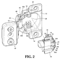
- the hinge assembly of the present invention comprises a housing 10, an arm 12, at least one spring 14, a maintaining member 16, a damper 18 and an adjustment member 20.
- the housing 10 comprises two side walls 22, an inner bottom 24, a front wall 26 and a rear wall 28, wherein the side walls 22 of the housing 10 have two pivotal holes 30, and the two pivotal holes 30 are located adjacent to the front wall 26.
- the side walls 22 further have two pin holes 32 and two positioning holes 34.
- the inner bottom 24 is connected between the two side walls 22.
- the inner bottom 24 is connected to the side walls 22, the front wall 26 and the rear wall 28.
- the front wall 26 is connected to the front end of the two side walls 22, and the rear wall 28 is connected to the rear end of the side walls 22.
- the chamber 36 of the housing 10 is defined by the two side walls 22, the inner bottom 24, the front wall 26 and the rear wall 28.
- the inner bottom 24 has two lugs 38, and each lug 38 has a through hole 40 which is located corresponding to the pin hole 32 corresponding thereto.
- the arm 12 is pivotably connected to the housing 10 and has two cam portions 42 and a reception portion 44 which is connected between the two cam portions 42.
- a pivot 46 extends through the pivotal holes 30 of the side walls 22 of the housing 10 and the reception portion 44 of the arm 12 to pivotably connect the arm 12 to the housing 10.
- An installation member 48 is connected to the arm 12 so as to be installed to a piece of furniture such as a cabinet.
- the at least one spring 14 is located in the chamber 36 to provide a force to allow the pivotal movement between the housing 10 and the arm 12.
- there are two springs 14 which are torsion springs.
- Each spring 14 has a first leg 50a, a second leg 50b and a coil portion 52 connected between the first and second legs 50a, 50b.
- Each spring 14 is connected between the side wall 22 and the lug 38.
- the housing 10 has two pin holes 32 in the side walls 22.
- a pin 54 extends through one of the pin holes 32, one of the coil portions 52 of the springs 14 and one of the through holes 40 of the lugs 38 to position one of the springs 14 in the chamber 36 of the housing 10.
- each of the side walls 22 has an insertion hole 56, and the second legs 50b are inserted in the insertion holes 56.
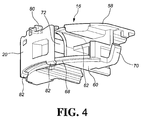
- the maintaining member 16 is secured in the chamber 36 of the housing 10 and has a top portion 58, a bottom portion 60 and a body 62 connected between the top and bottom portions 58, 60.
- the top portion 58 of the maintaining member 16 has a first index 64a and a second index 64b.
- the first index 64a is represented by a description "ON" marked thereon
- the second index 64b is represented by a description "OFF" marked thereon.
- the rear wall 28 has a first contact portion 66a and a second contact portion 66b on the periphery thereof.
- the first contact portion 66a of the maintaining member 16 is a fixed surface
- the second contact portion 66b of the maintaining member 16 is a resilient latch.
- the bottom portion 60 of the maintaining member 16 has a curved lip 68 on the periphery thereof.
- the maintaining member 16 has two engaging members 70 on two sides thereof, and the two engaging members 70 are engaged with the positioning holes 34 to secure the maintaining member 16 in the chamber 36 of the housing 10.
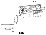
- the body 62 of the maintaining member 16 has a path 72.
- the path 72 has a linear guide section 74 defined in the inside thereof.
- the damper 18 is located in the path 72 and located corresponding to the arm 12.
- the damper 18 has a piston rod 76 and preferably a stop 78, wherein the piston rod 76 contacts the adjustment member 20, and the stop 78 is located to contact an end of the guide section 74.
- the adjustment member 20 is movably connected to the maintaining member 16 and comprises a top piece 80, a bottom piece 82 and a side panel 84 connected between the top and bottom pieces 80, 82.
- the top piece 80 of the adjustment member 20 contacts the top portion 58 of the maintaining member 16, and the bottom piece 82 of the adjustment member 20 contacts the bottom portion 60 of the maintaining member 16.
- the bottom piece 82 contacts the curved lip 68 of the bottom portion 60.
- the top piece 80 of the adjustment member 20 has a tip 86 on the front end thereof, and the top piece 80 further has an operation portion 88 on the top thereof, such as a pair of bent portions, so that the user can easily shift the adjustment member 20 by the user's finger(s).
- an operation portion 88 on the top thereof, such as a pair of bent portions, so that the user can easily shift the adjustment member 20 by the user's finger(s).
- the side panel 84 has a protrusion 90 and a protruded portion 92.
- the protrusion 90 is located adjacent to the top piece 80 and located corresponding to the first and second contact portions 66a, 66b of the maintaining member 16.
- the protruded portion 92 which is protruded into the maintaining member 16 and located corresponding to the piston rod 76 of the damper 18, as shown in Fig. 6 .
- the tip 86 points the first index 64a (ON) or the second index 64b (OFF) to indicate whether or not the protruded portion 92 of the adjustment member 20 contacts the piston rod 76 of the damper 18 to perform damping function.
- a resilient member 94 is connected between the maintaining member 16 and the adjustment member 20.
- the maintaining member 16 has a first hook 21 a
- the adjustment member 20 has a second hook 21b
- the resilient member 94 is hooked between the first and second hooks 21a, 21b, so that the adjustment member 20 is maintained at the first position in response the force of the resilient member 94.
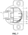
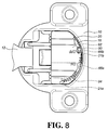
- Fig. 8 when the adjustment member 20 is moved to the second position relative to the maintaining member 16, the protrusion 90 of the adjustment member 20 is moved away from the first contact portion 66a and contacts the second contact portion 66b, and the adjustment member 20 stretches the resilient member 94.
- Fig. 9 shows that when the adjustment member 20 is moved to a second position relative to the maintaining member 16, the protruded portion 92 of the adjustment member 20 is moved away from the piston rod 76 of the damper 18, and the tip 86 points the second index 64b (OFF) of the maintaining member 16.
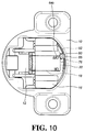
- Fig. 10 when the housing 10 is closed relative to the arm 12, although the damper 18 is moved by the arm 12 and shifts relative to the maintaining member 16, the piston rod 76 and the damper 18 are integrally moved toward the adjustment member 20 without any compression between the piston rod 76 and the damper 18. That is to say, the piston rod 76 cannot contact the protruded portion 92 of the adjustment member 20, so that no damping function is available.
- the arm 12 is connected to a cabinet 96 by the installation member 48, and the housing 10 is connected to a door 98.
- the user can adjust the adjustment member 20 to let the protruded portion 92 point the piston rod 76 of the damper 18, so that when the door 98 is moved to a closed position relative to the cabinet 96, as shown in Figs. 12 and 13 , the arm 12 contacts the damper 18 whose piston rod 76 contacts the protruded portion 92 of the adjustment member 20.
- the piston rod 76 retracts relative to the damper 18 to have the damping function. Therefore, the door 98 is slowly and quietly closed relative to the cabinet 96.
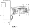
- Fig. 14 shows that when the door 98 is opened relative to the cabinet 96, the arm 12 is moved away from the damper 18, and the piston rod 76 extends and contacts the protruded portion 92 of the adjustment member 20 to move the damper 18 until the stop 78 of the damper 18 contacts the end of the linear guide section 74 of the maintaining member 16. At this position, the damper 18 can be pushed to perform damping function relative to the arm 12.
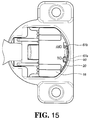
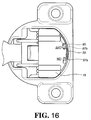
- the second embodiment is disclosed in Figs. 15 and 16 , wherein both of the first and second contact portions 67a, 67b of the maintaining member 16 are two resilient latches.
- the protrusion 90 of the adjustment member 20 contacts the first contact portion 67a and is positioned.
- the protrusion 90 of the adjustment member 20 moves away from the first contact portion 67a and contacts the second contact portion 67b and is positioned.
- the user can adjust the adjustment member 20 to have damping function or not based on the user's requirement. That is to say, the present invention provide a mechanism for the user to easily and conveniently choose turning on or turning off the damping function of the damping device for the hinge assembly.
Landscapes
- Closing And Opening Devices For Wings, And Checks For Wings (AREA)
Claims (15)
- Eine Scharnierbaugruppe, umfassend:ein Gehäuse (10) mit einer Kammer (36) in diesem; einem Ausleger (12), der drehgelenkig am Gehäuse (10) befestigt ist; einer Feder (14), die in der Kammer (36) befestigt ist, um für die Drehbewegung zwischen dem Gehäuse (10) und dem Ausleger (12) eine Kraft auszuüben;einem Dämpfer, der in der Kammer (36) montiert ist und ein Halteringsglied (16) aufweist, das in der Kammer (36) des Gehäuses (10) befestigt ist, wobei das Halterungsglied (16) mit einem Durchlass (72) gebildet und ein Dämpfer (18) in diesem Durchlass (72) in Übereinstimmung mit dem Ausleger (12) angeordnet ist; der Dämpfer (18) mit einer Kolbenstange (76) gebildet ist;einem Justierteil (20), das beweglich am Halterungsglied (16) befestigt und mit einem vorstehenden Teil (92) gebildet ist, dadurch gekennzeichnet, dass der vorstehende Teil (92) des Justierteils (20) in das Halteringsglied (16) ragt und in Übereinstimmung mit der Kolbenstange (76) des Dämpfers (18) angeordnet ist;beim Bewegen des Justierteils (20) in eine erste Position zum Halterungsglied (16) der vorstehende Teil (92) des Justierteils (20) auf die Kolbenstange (76) des Dämpfers (18) zu angeordnet wird, wenn das Gehäuse (10) zum Ausleger (12) geschlossen und der Dämpfer (18) mit dem Ausleger (12) angeschoben wird, damit die Kolbenstange (76) des Dämpfers (18) mit dem vorstehenden Teil (92) des Justierteils (20) in Berührung kommt und eingezogen wird, um eine dämpfende Funktion auszuüben, undbeim Bewegen des Justierteils (20) in eine zweite Position zum Halteringsglied (16) der vorstehende Teil (92) des Justierteils (20) von der Kolbenstange (76) des Dämpfers (18) wegbewegt wird, wenn das Gehäuse (10) zum Ausleger (12) geschlossen wird, die Kolbenstange (76) und der Dämpfer (18) zum Halteringsglied (16) auf den Justierteil (29) zu integral verschoben werden, wobei die Kolbenstange (76) des Dämpfers (18) nicht mit dem vorstehenden Teil (92) des Justierteils (20) in Berührung kommen kann, so dass keine dämpfende Funktion ausgeübt wird.
- Die Scharnierbaugruppe nach Anspruch 1, wobei der Justierteil (20) weiter mit einem Überstand (90) gebildet ist; das Halterungsglied (16) weist einen oberen Teil (58) auf, der mit einem ersten Kontaktteil (66a) und einem zweiten Kontaktteil (66b) an dessen Peripherie gebildet ist; beim Verschieben des Justierteils (20) in die erste Position zum Halterungsglied (16) der Überstand (90) des Justierteils (20) mit dem ersten Kontaktteil (66a) des Halteringsgliedes (16) in Berührung kommt; beim Verschieben des Justierteils (20) in die zweite Position zum Halterungsglied (16) der Überstand (90) des Justierteils (20) mit dem zweiten Kontaktteil (66b) des Halteringsgliedes (16) in Berührung kommt.
- Die Scharnierbaugruppe nach Anspruch 2, wobei der erste Kontaktteil (66a) des Halterungsgliedes (16) als eine feste Fläche und der zweite Kontaktteil (66b) des Halteringsgliedes (16) als einen elastischen Riegel gebildet sind.
- Die Scharnierbaugruppe nach Anspruch 3, weiter umfassend eine Feder (94), die zwischen dem Halterungsglied (16) und dem Justierteil (20) befestigt ist; der Justierteil (20) in der ersten Position als Reaktion auf die Feder (94) festgehalten wird.
- Die Scharnierbaugruppe nach Anspruch 4, wobei das Halteringsglied (16) eine erste Feder (21 a) aufweist, der Justierteil (20) eine zweite Feder (21 b) aufweist und die Feder (94) zwischen der ersten und zweiten Feder (21a, 21b) eingehakt ist.
- Die Scharnierbaugruppe nach Anspruch 2, wobei sowohl der erste als auch der zweite Kontaktteil (67a, 67b) des Halterungsgliedes (16) als zwei elastische Riegel gebildet sind.
- Die Scharnierbaugruppe nach Anspruch 2, wobei das Halterungsglied (16) mit einem unteren Teil (60) gebildet ist, der an dessen Peripherie eine gebogene Lippe (68) aufweist; das Halterungsglied (16) mit einem Körper (62) gebildet ist, der zwischen dem oberen Teil (58) und dem unteren Teil (60) befestigt ist; der Justierteil (20) mit einem oberen Stück (80), einem unteren Stück (82) und mit einer Seitenverkleidung (84) gebildet ist, wobei letzteres zwischen dem oberen und dem unteren Stück (80, 82) befestigt ist; das obere Stück (80) des Justierteils (20) mit dem oberen Teil (58) des Halteringsgliedes (16) und das untere Stück (82) des Justierteils (20) mit der Lippe (68) des unteren Teils (60) des Halteringsgliedes (16) in Berührung kommen.
- Die Scharnierbaugruppe nach Anspruch 7, wobei das obere Stück (80) des Justierteils (20) mit einem Betätigungsteil (88) gebildet ist.
- Die Scharnierbaugruppe nach Anspruch 7, wobei der obere Teil (58) des Halterungsgliedes (16) einen ersten Zeiger (64a) und einen zweiten Zeiger (64b) aufweist; das obere Stück (80) des Justierteils (20) mit einer Spitze (86) gebildet ist; beim Verschieben des Justierteils (20) in die erste Position zum Halterungsglied (16) die Spitze (86) den ersten Zeiger (64a) und beim Verschieben des Justierteils (20) in die zweite Position zum Halterungsglied (16) die Spitze (86) den zweiten Zeiger (64b) ausrichtet.
- Die Scharnierbaugruppe nach Anspruch 9, wobei der erste Zeiger (64a) mit einer Kennzeichnung "ON" (EIN) und der zweite Zeiger (64b) mit einer Kennzeichnung "OFF" (AUS) bezeichnet sind.
- Die Scharnierbaugruppe nach Anspruch 1, wobei der Durchlass (72) des Halterungsgliedes (16) auf einer Innenseite mit einer linearen Führungskomponente (74) gebildet ist; der Dämpfer (18) mit einem Anschlag (78) gebildet ist, der so angeordnet ist, damit er mit einem Ende der Führungskomponente (74) in Berührung kommt.
- Die Scharnierbaugruppe nach Anspruch 1, wobei die Kammer (36) im Gehäuse (10) zwei Positionierlöcher (34) aufweist; das Halterungsglied (16) auf dessen beiden Seiten mit zwei Eingriffteilen (70) gebildet ist; die beiden Eingriffteile (70) mit den Positionierlöchern (34) in Eingriff sind, um das Haltertingsglied (16) in der Kammer (36) im Gehäuse (10) sicher zu befestigen.
- Die Scharnierbaugruppe nach Anspruch 1, wobei die Kammer (36) im Gehäuse (10) mit zwei Seitenwänden (22), einer inneren Bodenfläche (24), einer vorderen Wand (26) und mit einer hinteren Wand (28) gebildet wird; die vordere Wand (26) an einem vorderen Ende der beiden Seitenwände (22) und die hintere Wand (28) an einem hinteren Ende der Seitenwände (22) befestigt sind; jede der Seitenwände (22) des Gehäuses (10) eine Scharnierbohrung (30) aufweist; die beiden Schanlierbohrungen (30) angrenzend an der vorderen Wand (26) gebildet sind; der Ausleger (12) zwei Nocken (42) und einen Aufnahmeteil (44) aufweist, der zwischen den beiden Nocken (42) befestigt ist; ein Drehzapfen (46) durch die Scharnierbohrungen (30) und durch den Aufnahmeteil (44) ragt, um drehgelenkig am Ausleger (12) des Gehäuses (10) befestigt zu werden.
- Die Scharnierbaugruppe nach Anspruch 1, wobei zwei Federn (14) vorgesehen sind, die als Torsionsfedern gebildet sind, wobei jede Feder (14) mit einem ersten Bein (50a), einem zweiten Bein (50b) gebildet ist und eine Spule (52) zwischen dem ersten und zweiten Bein (50a, 50b) befestigt ist; das Gehäuse (10) in den Seitenwänden (22) zwei Bolzenlöcher (32) aufweist; die innere Bodenfläche (24) zwei Ösen (38) aufweist; jede Öse (38) ein durchgehendes Loch (40) aufweist, das in Übereinstimmung mit dem entsprechenden Bolzenloch (32) gebildet ist; die Federn (14) zwischen den Seitenwände (22) des Gehäuses (10) und den Ösen (38) befestigt sind; ein Bolzen (54) durch einen der Bolzenlöcher (32) ragt; eine der Spulen (52) der Federn (14) und eines der durchgehenden Löcher (40) der Ösen (38) mit einer der Federn (14) am Gehäuse (10) befestigt sind.
- Die Scharnierbaugruppe nach Anspruch 14, wobei die beiden Seitenwände (22) je ein Einsteckloch (56) aufweisen und die beiden jeweiligen zweiten Beine (50b) der beiden Federn (14) in die beiden Einstecklöcher (56) eingeführt sind.
Priority Applications (1)
| Application Number | Priority Date | Filing Date | Title |
|---|---|---|---|
| EP12198584.0A EP2746509B1 (de) | 2012-12-20 | 2012-12-20 | Dämpfvorrichtung für eine Scharnieranordnung |
Applications Claiming Priority (1)
| Application Number | Priority Date | Filing Date | Title |
|---|---|---|---|
| EP12198584.0A EP2746509B1 (de) | 2012-12-20 | 2012-12-20 | Dämpfvorrichtung für eine Scharnieranordnung |
Publications (2)
| Publication Number | Publication Date |
|---|---|
| EP2746509A1 EP2746509A1 (de) | 2014-06-25 |
| EP2746509B1 true EP2746509B1 (de) | 2016-10-19 |
Family
ID=47559176
Family Applications (1)
| Application Number | Title | Priority Date | Filing Date |
|---|---|---|---|
| EP12198584.0A Active EP2746509B1 (de) | 2012-12-20 | 2012-12-20 | Dämpfvorrichtung für eine Scharnieranordnung |
Country Status (1)
| Country | Link |
|---|---|
| EP (1) | EP2746509B1 (de) |
Families Citing this family (6)
| Publication number | Priority date | Publication date | Assignee | Title |
|---|---|---|---|---|
| GB2520480B (en) * | 2013-11-05 | 2020-08-12 | Titus D O O Dekani | Improvements in hinge assemblies |
| GB2529250B (en) * | 2014-08-15 | 2020-09-09 | Titus Doo Dekani | Improvements in hinge assemblies |
| WO2016102216A1 (en) * | 2014-12-23 | 2016-06-30 | Arturo Salice S.P.A. | Hinge for pieces of furniture with deactivatable deceleration device |
| US10344517B2 (en) | 2015-10-15 | 2019-07-09 | Hardware Resources, Inc. | Soft close device for compact hinges |
| TWI597432B (zh) | 2015-11-26 | 2017-09-01 | 川湖科技股份有限公司 | 鉸鏈及其緩衝裝置 |
| ES1286345Y (es) | 2022-01-18 | 2022-05-09 | Ind Galtes S A | Bisagra hidráulica para puertas de vidrio |
Family Cites Families (4)
| Publication number | Priority date | Publication date | Assignee | Title |
|---|---|---|---|---|
| US7552509B2 (en) * | 2006-11-15 | 2009-06-30 | King Slide Works Co., Ltd. | Hinge buffer device |
| AT506643A1 (de) * | 2008-04-11 | 2009-10-15 | Blum Gmbh Julius | Dämpfvorrichtung zur dämpfung einer öffnungs- und/oder schliessbewegung eines möbelbeschlages |
| AT509720B1 (de) | 2010-08-23 | 2011-11-15 | Blum Gmbh Julius | Dämpfvorrichtung für möbelteile |
| DE102011050053B4 (de) * | 2011-05-03 | 2024-07-18 | Hettich-Oni Gmbh & Co. Kg | Scharnier |
-
2012
- 2012-12-20 EP EP12198584.0A patent/EP2746509B1/de active Active
Also Published As
| Publication number | Publication date |
|---|---|
| EP2746509A1 (de) | 2014-06-25 |
Similar Documents
| Publication | Publication Date | Title |
|---|---|---|
| US8561262B1 (en) | Damping device for hinge assembly | |
| US8650711B1 (en) | Hinge assembly with damping device | |
| EP2746509A1 (de) | Dämpfvorrichtung für eine Scharnieranordnung | |
| US8601644B1 (en) | Device for installing damping member to hinge unit | |
| EP2749722B1 (de) | Scharnieranordnung mit Dämpfvorrichtung | |
| US9372001B2 (en) | Home cooking appliance with a side swing oven door having an integral self capturing latch | |
| CN101173582A (zh) | 可缓冲的铰链 | |
| EP3080373B1 (de) | Scharnier für backofentüren | |
| CN103867057B (zh) | 缓冲铰链 | |
| EP3655608B1 (de) | Scharnier für küchenofen | |
| JP2006299533A (ja) | 収納家具 | |
| KR101193477B1 (ko) | 오븐기용 도어 힌지 장치 | |
| EP2336689A2 (de) | Türgriff für Haushaltskühlvorrichtung | |
| US9556660B2 (en) | Damped hinge assemblies | |
| CN111350429A (zh) | 一种缓冲铰链快速拆装结构 | |
| KR20120041388A (ko) | 상하 개폐식 가구 도어용 경첩 | |
| CN103850563A (zh) | 铰链的缓冲装置 | |
| TWI476318B (zh) | 緩衝鉸鍊 | |
| KR102046492B1 (ko) | 탄성이 조절되는 가구용 손잡이 | |
| EP2706180B1 (de) | Vorrichtung zum Installieren eines Dämpfungselements an einer Scharniereinheit | |
| TWI476319B (zh) | 鉸鍊的緩衝裝置 | |
| AU2021362148A1 (en) | A door hinge for household appliances | |
| TWI441976B (zh) | 具有緩衝裝置的鉸鍊 | |
| US20210396399A1 (en) | Concealed handle and air conditioning device with the same | |
| EP1804012B1 (de) | Verbesserter Türgriff für Kühlgerät |
Legal Events
| Date | Code | Title | Description |
|---|---|---|---|
| PUAI | Public reference made under article 153(3) epc to a published international application that has entered the european phase |
Free format text: ORIGINAL CODE: 0009012 |
|
| 17P | Request for examination filed |
Effective date: 20130819 |
|
| AK | Designated contracting states |
Kind code of ref document: A1 Designated state(s): AL AT BE BG CH CY CZ DE DK EE ES FI FR GB GR HR HU IE IS IT LI LT LU LV MC MK MT NL NO PL PT RO RS SE SI SK SM TR |
|
| AX | Request for extension of the european patent |
Extension state: BA ME |
|
| 17Q | First examination report despatched |
Effective date: 20150430 |
|
| GRAP | Despatch of communication of intention to grant a patent |
Free format text: ORIGINAL CODE: EPIDOSNIGR1 |
|
| INTG | Intention to grant announced |
Effective date: 20160509 |
|
| GRAS | Grant fee paid |
Free format text: ORIGINAL CODE: EPIDOSNIGR3 |
|
| GRAA | (expected) grant |
Free format text: ORIGINAL CODE: 0009210 |
|
| AK | Designated contracting states |
Kind code of ref document: B1 Designated state(s): AL AT BE BG CH CY CZ DE DK EE ES FI FR GB GR HR HU IE IS IT LI LT LU LV MC MK MT NL NO PL PT RO RS SE SI SK SM TR |
|
| REG | Reference to a national code |
Ref country code: GB Ref legal event code: FG4D |
|
| REG | Reference to a national code |
Ref country code: CH Ref legal event code: EP |
|
| REG | Reference to a national code |
Ref country code: AT Ref legal event code: REF Ref document number: 838505 Country of ref document: AT Kind code of ref document: T Effective date: 20161115 |
|
| REG | Reference to a national code |
Ref country code: IE Ref legal event code: FG4D |
|
| REG | Reference to a national code |
Ref country code: DE Ref legal event code: R096 Ref document number: 602012024275 Country of ref document: DE |
|
| REG | Reference to a national code |
Ref country code: NL Ref legal event code: MP Effective date: 20161019 |
|
| REG | Reference to a national code |
Ref country code: LT Ref legal event code: MG4D |
|
| PG25 | Lapsed in a contracting state [announced via postgrant information from national office to epo] |
Ref country code: LV Free format text: LAPSE BECAUSE OF FAILURE TO SUBMIT A TRANSLATION OF THE DESCRIPTION OR TO PAY THE FEE WITHIN THE PRESCRIBED TIME-LIMIT Effective date: 20161019 |
|
| REG | Reference to a national code |
Ref country code: AT Ref legal event code: MK05 Ref document number: 838505 Country of ref document: AT Kind code of ref document: T Effective date: 20161019 |
|
| PG25 | Lapsed in a contracting state [announced via postgrant information from national office to epo] |
Ref country code: LT Free format text: LAPSE BECAUSE OF FAILURE TO SUBMIT A TRANSLATION OF THE DESCRIPTION OR TO PAY THE FEE WITHIN THE PRESCRIBED TIME-LIMIT Effective date: 20161019 Ref country code: SE Free format text: LAPSE BECAUSE OF FAILURE TO SUBMIT A TRANSLATION OF THE DESCRIPTION OR TO PAY THE FEE WITHIN THE PRESCRIBED TIME-LIMIT Effective date: 20161019 Ref country code: NO Free format text: LAPSE BECAUSE OF FAILURE TO SUBMIT A TRANSLATION OF THE DESCRIPTION OR TO PAY THE FEE WITHIN THE PRESCRIBED TIME-LIMIT Effective date: 20170119 |
|
| PG25 | Lapsed in a contracting state [announced via postgrant information from national office to epo] |
Ref country code: BE Free format text: LAPSE BECAUSE OF FAILURE TO SUBMIT A TRANSLATION OF THE DESCRIPTION OR TO PAY THE FEE WITHIN THE PRESCRIBED TIME-LIMIT Effective date: 20161019 Ref country code: HR Free format text: LAPSE BECAUSE OF FAILURE TO SUBMIT A TRANSLATION OF THE DESCRIPTION OR TO PAY THE FEE WITHIN THE PRESCRIBED TIME-LIMIT Effective date: 20161019 Ref country code: FI Free format text: LAPSE BECAUSE OF FAILURE TO SUBMIT A TRANSLATION OF THE DESCRIPTION OR TO PAY THE FEE WITHIN THE PRESCRIBED TIME-LIMIT Effective date: 20161019 Ref country code: RS Free format text: LAPSE BECAUSE OF FAILURE TO SUBMIT A TRANSLATION OF THE DESCRIPTION OR TO PAY THE FEE WITHIN THE PRESCRIBED TIME-LIMIT Effective date: 20161019 Ref country code: IS Free format text: LAPSE BECAUSE OF FAILURE TO SUBMIT A TRANSLATION OF THE DESCRIPTION OR TO PAY THE FEE WITHIN THE PRESCRIBED TIME-LIMIT Effective date: 20170219 Ref country code: NL Free format text: LAPSE BECAUSE OF FAILURE TO SUBMIT A TRANSLATION OF THE DESCRIPTION OR TO PAY THE FEE WITHIN THE PRESCRIBED TIME-LIMIT Effective date: 20161019 Ref country code: AT Free format text: LAPSE BECAUSE OF FAILURE TO SUBMIT A TRANSLATION OF THE DESCRIPTION OR TO PAY THE FEE WITHIN THE PRESCRIBED TIME-LIMIT Effective date: 20161019 Ref country code: PT Free format text: LAPSE BECAUSE OF FAILURE TO SUBMIT A TRANSLATION OF THE DESCRIPTION OR TO PAY THE FEE WITHIN THE PRESCRIBED TIME-LIMIT Effective date: 20170220 Ref country code: PL Free format text: LAPSE BECAUSE OF FAILURE TO SUBMIT A TRANSLATION OF THE DESCRIPTION OR TO PAY THE FEE WITHIN THE PRESCRIBED TIME-LIMIT Effective date: 20161019 Ref country code: ES Free format text: LAPSE BECAUSE OF FAILURE TO SUBMIT A TRANSLATION OF THE DESCRIPTION OR TO PAY THE FEE WITHIN THE PRESCRIBED TIME-LIMIT Effective date: 20161019 |
|
| REG | Reference to a national code |
Ref country code: DE Ref legal event code: R097 Ref document number: 602012024275 Country of ref document: DE |
|
| PG25 | Lapsed in a contracting state [announced via postgrant information from national office to epo] |
Ref country code: DK Free format text: LAPSE BECAUSE OF FAILURE TO SUBMIT A TRANSLATION OF THE DESCRIPTION OR TO PAY THE FEE WITHIN THE PRESCRIBED TIME-LIMIT Effective date: 20161019 Ref country code: RO Free format text: LAPSE BECAUSE OF FAILURE TO SUBMIT A TRANSLATION OF THE DESCRIPTION OR TO PAY THE FEE WITHIN THE PRESCRIBED TIME-LIMIT Effective date: 20161019 Ref country code: SK Free format text: LAPSE BECAUSE OF FAILURE TO SUBMIT A TRANSLATION OF THE DESCRIPTION OR TO PAY THE FEE WITHIN THE PRESCRIBED TIME-LIMIT Effective date: 20161019 Ref country code: CZ Free format text: LAPSE BECAUSE OF FAILURE TO SUBMIT A TRANSLATION OF THE DESCRIPTION OR TO PAY THE FEE WITHIN THE PRESCRIBED TIME-LIMIT Effective date: 20161019 Ref country code: EE Free format text: LAPSE BECAUSE OF FAILURE TO SUBMIT A TRANSLATION OF THE DESCRIPTION OR TO PAY THE FEE WITHIN THE PRESCRIBED TIME-LIMIT Effective date: 20161019 |
|
| REG | Reference to a national code |
Ref country code: CH Ref legal event code: PL |
|
| PLBE | No opposition filed within time limit |
Free format text: ORIGINAL CODE: 0009261 |
|
| STAA | Information on the status of an ep patent application or granted ep patent |
Free format text: STATUS: NO OPPOSITION FILED WITHIN TIME LIMIT |
|
| PG25 | Lapsed in a contracting state [announced via postgrant information from national office to epo] |
Ref country code: IT Free format text: LAPSE BECAUSE OF FAILURE TO SUBMIT A TRANSLATION OF THE DESCRIPTION OR TO PAY THE FEE WITHIN THE PRESCRIBED TIME-LIMIT Effective date: 20161019 Ref country code: BG Free format text: LAPSE BECAUSE OF FAILURE TO SUBMIT A TRANSLATION OF THE DESCRIPTION OR TO PAY THE FEE WITHIN THE PRESCRIBED TIME-LIMIT Effective date: 20170119 Ref country code: SM Free format text: LAPSE BECAUSE OF FAILURE TO SUBMIT A TRANSLATION OF THE DESCRIPTION OR TO PAY THE FEE WITHIN THE PRESCRIBED TIME-LIMIT Effective date: 20161019 |
|
| 26N | No opposition filed |
Effective date: 20170720 |
|
| PG25 | Lapsed in a contracting state [announced via postgrant information from national office to epo] |
Ref country code: MC Free format text: LAPSE BECAUSE OF FAILURE TO SUBMIT A TRANSLATION OF THE DESCRIPTION OR TO PAY THE FEE WITHIN THE PRESCRIBED TIME-LIMIT Effective date: 20161019 |
|
| REG | Reference to a national code |
Ref country code: FR Ref legal event code: ST Effective date: 20170831 |
|
| REG | Reference to a national code |
Ref country code: IE Ref legal event code: MM4A |
|
| PG25 | Lapsed in a contracting state [announced via postgrant information from national office to epo] |
Ref country code: FR Free format text: LAPSE BECAUSE OF NON-PAYMENT OF DUE FEES Effective date: 20170102 Ref country code: LI Free format text: LAPSE BECAUSE OF NON-PAYMENT OF DUE FEES Effective date: 20161231 Ref country code: CH Free format text: LAPSE BECAUSE OF NON-PAYMENT OF DUE FEES Effective date: 20161231 Ref country code: LU Free format text: LAPSE BECAUSE OF NON-PAYMENT OF DUE FEES Effective date: 20161220 |
|
| PG25 | Lapsed in a contracting state [announced via postgrant information from national office to epo] |
Ref country code: SI Free format text: LAPSE BECAUSE OF FAILURE TO SUBMIT A TRANSLATION OF THE DESCRIPTION OR TO PAY THE FEE WITHIN THE PRESCRIBED TIME-LIMIT Effective date: 20161019 Ref country code: IE Free format text: LAPSE BECAUSE OF NON-PAYMENT OF DUE FEES Effective date: 20161220 |
|
| PG25 | Lapsed in a contracting state [announced via postgrant information from national office to epo] |
Ref country code: HU Free format text: LAPSE BECAUSE OF FAILURE TO SUBMIT A TRANSLATION OF THE DESCRIPTION OR TO PAY THE FEE WITHIN THE PRESCRIBED TIME-LIMIT; INVALID AB INITIO Effective date: 20121220 |
|
| PG25 | Lapsed in a contracting state [announced via postgrant information from national office to epo] |
Ref country code: CY Free format text: LAPSE BECAUSE OF FAILURE TO SUBMIT A TRANSLATION OF THE DESCRIPTION OR TO PAY THE FEE WITHIN THE PRESCRIBED TIME-LIMIT Effective date: 20161019 Ref country code: MK Free format text: LAPSE BECAUSE OF FAILURE TO SUBMIT A TRANSLATION OF THE DESCRIPTION OR TO PAY THE FEE WITHIN THE PRESCRIBED TIME-LIMIT Effective date: 20161019 Ref country code: GR Free format text: LAPSE BECAUSE OF FAILURE TO SUBMIT A TRANSLATION OF THE DESCRIPTION OR TO PAY THE FEE WITHIN THE PRESCRIBED TIME-LIMIT Effective date: 20161019 |
|
| PG25 | Lapsed in a contracting state [announced via postgrant information from national office to epo] |
Ref country code: MT Free format text: LAPSE BECAUSE OF NON-PAYMENT OF DUE FEES Effective date: 20161220 |
|
| PG25 | Lapsed in a contracting state [announced via postgrant information from national office to epo] |
Ref country code: TR Free format text: LAPSE BECAUSE OF FAILURE TO SUBMIT A TRANSLATION OF THE DESCRIPTION OR TO PAY THE FEE WITHIN THE PRESCRIBED TIME-LIMIT Effective date: 20161019 |
|
| PG25 | Lapsed in a contracting state [announced via postgrant information from national office to epo] |
Ref country code: AL Free format text: LAPSE BECAUSE OF FAILURE TO SUBMIT A TRANSLATION OF THE DESCRIPTION OR TO PAY THE FEE WITHIN THE PRESCRIBED TIME-LIMIT Effective date: 20161019 |
|
| PGFP | Annual fee paid to national office [announced via postgrant information from national office to epo] |
Ref country code: DE Payment date: 20251013 Year of fee payment: 14 |
|
| PGFP | Annual fee paid to national office [announced via postgrant information from national office to epo] |
Ref country code: GB Payment date: 20251008 Year of fee payment: 14 |