EP2746573A2 - Ensembles de pales de rotor et procédés d'assemblage de ceux-ci - Google Patents
Ensembles de pales de rotor et procédés d'assemblage de ceux-ci Download PDFInfo
- Publication number
- EP2746573A2 EP2746573A2 EP13196910.7A EP13196910A EP2746573A2 EP 2746573 A2 EP2746573 A2 EP 2746573A2 EP 13196910 A EP13196910 A EP 13196910A EP 2746573 A2 EP2746573 A2 EP 2746573A2
- Authority
- EP
- European Patent Office
- Prior art keywords
- spar cap
- segment
- blade
- blade segment
- shell portion
- Prior art date
- Legal status (The legal status is an assumption and is not a legal conclusion. Google has not performed a legal analysis and makes no representation as to the accuracy of the status listed.)
- Withdrawn
Links
- 238000000034 method Methods 0.000 title claims abstract description 31
- 230000000712 assembly Effects 0.000 title description 5
- 238000000429 assembly Methods 0.000 title description 5
- 239000000853 adhesive Substances 0.000 claims abstract description 19
- 230000001070 adhesive effect Effects 0.000 claims abstract description 19
- 238000007789 sealing Methods 0.000 claims abstract description 17
- 210000001503 joint Anatomy 0.000 claims abstract description 12
- 239000002131 composite material Substances 0.000 claims description 9
- 239000011521 glass Substances 0.000 claims description 7
- 239000004593 Epoxy Substances 0.000 claims description 6
- 238000002347 injection Methods 0.000 claims description 6
- 239000007924 injection Substances 0.000 claims description 6
- 239000000463 material Substances 0.000 description 8
- 239000011162 core material Substances 0.000 description 5
- 238000004519 manufacturing process Methods 0.000 description 3
- OKTJSMMVPCPJKN-UHFFFAOYSA-N Carbon Chemical compound [C] OKTJSMMVPCPJKN-UHFFFAOYSA-N 0.000 description 2
- 238000004026 adhesive bonding Methods 0.000 description 2
- 229910052799 carbon Inorganic materials 0.000 description 2
- 238000010276 construction Methods 0.000 description 2
- 238000001723 curing Methods 0.000 description 2
- 238000013461 design Methods 0.000 description 2
- 230000007246 mechanism Effects 0.000 description 2
- 230000000007 visual effect Effects 0.000 description 2
- HECLRDQVFMWTQS-RGOKHQFPSA-N 1755-01-7 Chemical compound C1[C@H]2[C@@H]3CC=C[C@@H]3[C@@H]1C=C2 HECLRDQVFMWTQS-RGOKHQFPSA-N 0.000 description 1
- 229920000049 Carbon (fiber) Polymers 0.000 description 1
- VVQNEPGJFQJSBK-UHFFFAOYSA-N Methyl methacrylate Chemical class COC(=O)C(C)=C VVQNEPGJFQJSBK-UHFFFAOYSA-N 0.000 description 1
- 240000007182 Ochroma pyramidale Species 0.000 description 1
- 230000009471 action Effects 0.000 description 1
- 230000004075 alteration Effects 0.000 description 1
- 230000008901 benefit Effects 0.000 description 1
- 239000004917 carbon fiber Substances 0.000 description 1
- 238000007796 conventional method Methods 0.000 description 1
- 230000008878 coupling Effects 0.000 description 1
- 238000010168 coupling process Methods 0.000 description 1
- 238000005859 coupling reaction Methods 0.000 description 1
- ZSWFCLXCOIISFI-UHFFFAOYSA-N cyclopentadiene Chemical class C1C=CC=C1 ZSWFCLXCOIISFI-UHFFFAOYSA-N 0.000 description 1
- 230000003247 decreasing effect Effects 0.000 description 1
- 125000003700 epoxy group Chemical group 0.000 description 1
- 239000000835 fiber Substances 0.000 description 1
- 239000006260 foam Substances 0.000 description 1
- 239000003365 glass fiber Substances 0.000 description 1
- 238000005304 joining Methods 0.000 description 1
- VNWKTOKETHGBQD-UHFFFAOYSA-N methane Chemical compound C VNWKTOKETHGBQD-UHFFFAOYSA-N 0.000 description 1
- 229920000647 polyepoxide Polymers 0.000 description 1
- 229920000728 polyester Polymers 0.000 description 1
- 239000004814 polyurethane Substances 0.000 description 1
- 229920002635 polyurethane Polymers 0.000 description 1
- 230000008569 process Effects 0.000 description 1
- 230000008439 repair process Effects 0.000 description 1
- 238000009420 retrofitting Methods 0.000 description 1
- 239000000565 sealant Substances 0.000 description 1
- 238000006467 substitution reaction Methods 0.000 description 1
- 150000003673 urethanes Chemical class 0.000 description 1
- 229920001567 vinyl ester resin Polymers 0.000 description 1
- 239000011800 void material Substances 0.000 description 1
Images



Classifications
-
- F—MECHANICAL ENGINEERING; LIGHTING; HEATING; WEAPONS; BLASTING
- F03—MACHINES OR ENGINES FOR LIQUIDS; WIND, SPRING, OR WEIGHT MOTORS; PRODUCING MECHANICAL POWER OR A REACTIVE PROPULSIVE THRUST, NOT OTHERWISE PROVIDED FOR
- F03D—WIND MOTORS
- F03D1/00—Wind motors with rotation axis substantially parallel to the air flow entering the rotor
- F03D1/06—Rotors
- F03D1/065—Rotors characterised by their construction elements
- F03D1/0675—Rotors characterised by their construction elements of the blades
-
- F—MECHANICAL ENGINEERING; LIGHTING; HEATING; WEAPONS; BLASTING
- F03—MACHINES OR ENGINES FOR LIQUIDS; WIND, SPRING, OR WEIGHT MOTORS; PRODUCING MECHANICAL POWER OR A REACTIVE PROPULSIVE THRUST, NOT OTHERWISE PROVIDED FOR
- F03D—WIND MOTORS
- F03D13/00—Assembly, mounting or commissioning of wind motors; Arrangements specially adapted for transporting wind motor components
- F03D13/10—Assembly of wind motors; Arrangements for erecting wind motors
-
- F—MECHANICAL ENGINEERING; LIGHTING; HEATING; WEAPONS; BLASTING
- F05—INDEXING SCHEMES RELATING TO ENGINES OR PUMPS IN VARIOUS SUBCLASSES OF CLASSES F01-F04
- F05B—INDEXING SCHEME RELATING TO WIND, SPRING, WEIGHT, INERTIA OR LIKE MOTORS, TO MACHINES OR ENGINES FOR LIQUIDS COVERED BY SUBCLASSES F03B, F03D AND F03G
- F05B2240/00—Components
- F05B2240/20—Rotors
- F05B2240/30—Characteristics of rotor blades, i.e. of any element transforming dynamic fluid energy to or from rotational energy and being attached to a rotor
- F05B2240/302—Segmented or sectional blades
-
- Y—GENERAL TAGGING OF NEW TECHNOLOGICAL DEVELOPMENTS; GENERAL TAGGING OF CROSS-SECTIONAL TECHNOLOGIES SPANNING OVER SEVERAL SECTIONS OF THE IPC; TECHNICAL SUBJECTS COVERED BY FORMER USPC CROSS-REFERENCE ART COLLECTIONS [XRACs] AND DIGESTS
- Y02—TECHNOLOGIES OR APPLICATIONS FOR MITIGATION OR ADAPTATION AGAINST CLIMATE CHANGE
- Y02E—REDUCTION OF GREENHOUSE GAS [GHG] EMISSIONS, RELATED TO ENERGY GENERATION, TRANSMISSION OR DISTRIBUTION
- Y02E10/00—Energy generation through renewable energy sources
- Y02E10/70—Wind energy
- Y02E10/72—Wind turbines with rotation axis in wind direction
Definitions
- the subject matter disclosed herein relates generally to rotor blades and, more specifically, to methods of assembling jointed rotor blades.
- a modem wind turbine typically includes a tower, generator, gearbox, nacelle, and one or more rotor blades.
- the rotor blades capture kinetic energy of wind using known airfoil principles.
- the rotor blades transmit the kinetic energy in the form of rotational energy so as to turn a shaft coupling the rotor blades to a gearbox, or if a gearbox is not used, directly to the generator.
- the generator then converts the mechanical energy to electrical energy that may be deployed to a utility grid.
- the construction of a modem rotor blade generally includes skin or shell components and one or more internal structural components, such as spar caps and one or more shear webs.
- the skin/shell typically manufactured from layers of fiber composite and/or a lightweight core material, forms the exterior aerodynamic airfoil shape of the rotor blade.
- the spar caps provide increased rotor blade strength by integrating one or more structural elements running along the length of the rotor blade on both interior sides of the rotor blade.
- Shear webs are structural beam-like components running essentially perpendicular between the top and bottom spar caps and extending across the interior portion of the rotor blade between the outer skins.
- Spar caps have typically been constructed from glass fiber reinforced composites, though some larger blades may include spar caps constructed from carbon fiber reinforced composites.
- the size, shape, and weight of rotor blades are factors that generally contribute to energy efficiencies of wind turbines. For example, an increase in rotor blade size can increase the energy production of a wind turbine. Thus, to ensure that wind power remains a viable energy power source, efforts have been made to increase energy outputs by increasing the length wind turbine blades. For instance, larger wind turbines may have rotor blades 70 meters in radius and larger.
- known rotor blade assemblies may be formed as a two-piece construction, having both a fully formed tip piece and a fully formed root piece.
- known methods require that both the skin/shell components and internal structural components of the pieces be attached simultaneously.
- the internal structural components of the pieces are often connected blindly, as physical and visual access to such components is blocked by the outer shell components. With such blind connections, it is often difficult and/or impossible to ensure that the internal structural components of the root piece and the tip piece are connected properly.
- a method of assembling a rotor blade includes providing a first blade segment comprising a first shell portion and at least two first spar cap segments and providing a second blade segment comprising a second shell portion and at least two second spar cap segments.
- An access region is defined in at least one of the first shell portion and the second shell portion.
- the method further includes inserting the second blade segment into the first blade segment, wherein a spar cap cavity is formed between each set of corresponding first and second spar cap segments, and wherein an access window is defined by the access region at an interface between the first blade segment and the second blade segment, the access window providing access to the spar cap cavities.
- the method finally includes sealing the spar cap cavities and injecting an adhesive into the spar cap cavities to bond the blade segments together, wherein a scarf joint is formed between each set of corresponding first and second spar cap segments.
- a rotor blade assembly in another embodiment, includes a first blade segment comprising a first shell portion and at least two first spar cap segments, and a second blade segment comprising a second shell portion and at least two second spar cap segments, wherein an access region is defined in at least one of the first shell portion and the second shell portion.
- the second blade segment is inserted into the first blade segment a spar cap cavity is formed between each set of corresponding first and second spar cap segments, and wherein an access window is defined by the access region at an interface between the first blade segment and the second blade segment, the access window providing access to the spar cap cavities.
- Embodiments disclosed herein include methods of assembling a jointed rotor blade.
- the methods allow transport of blade components to a secondary site or field site where the components can be assembled to form the turbine blade.
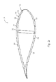
- a rotor blade 10 includes a first blade segment 12 and a second blade segment 14.
- the first and second blade segments 12 and 14 are each hollow segments comprising a first shell portion 19 and a second shell portion 21 respectively.
- the first shell portion 19 and the second shell portion 21 can each comprise outer skin 18, skin core 20, and inner skin 22.
- the outer skin 18, skin core 20, and inner skin 22 are made from materials that are light-weight and strong.
- the first blade segment 12 includes at least two first spar cap segments 26, and the second blade segment 14 includes at least two second spar cap segments 28.
- the first and second spar cap segments 26, 28 are configured to form a scarf joint there between.
- a shear web 32 connects the first spar cap segments 26 in the first blade segment 12.
- a shear web 32 connects the second spar cap segments 28 in the second blade segment 14.
- the spar cap segments bear longitudinal-loads experienced by the rotor blades and are attached to the inner skin 22 of the respective blade segments.
- the outer skin 18 and spar cap segments 26 and 28 are comprised of composite glass or carbon
- the skin core 20 and shear web 32 are comprised of foam or balsa.
- an access region 25 is defined in at least one of the first shell portion 19 and the second shell portion 21.
- the access region 25 can define an access window 27 when the second blade segment 14 is inserted into the first blade segment 12 such that the access window 27 provides access to an interior of the rotor blade 10.
- the access region 25 may generally comprise any opening or removed area defined and/or formed in the skin/shell of the rotor blade 10 and may have any suitable length.
- the access region 25 can comprise any shape or configuration comprising a lack of shell portion 19, 21.
- the access region 25 may only be defined in either the first shell portion 19 of the first blade segment 12 or in only the second shell portion 21 of the second blade segment 14.
- the access region 25 may be defined in both the first shell portion 19 of the first blade segment 12 as well as the second shell portion 21 of the second blade segment 14.
- the access region 25 may be disposed at a variety of positions around the circumference of the rotor blade 10.
- the access region 25 may be formed at the leading edge or the trailing edge of at least one of the first blade segment 12 and the second blade segment 14. As illustrated in Figs.
- the second blade segment 14 is inserted into the first blade segment 12 wherein a spar cap cavity 36 and scarf joint 38 are formed between each corresponding set of first and second spar cap segments 26, 28.
- the spar cap cavity 36 specifically comprises the void between the first and second spar cap segments 26, 28 and can be defined by two longitudinal sides 37 and two transverse sides 39.
- the spar cap cavity 36 and its boundary sides 37, 39 can vary in configuration based on the respective shapes of the first and second spar cap segments 26, 28.
- the spar cap cavity can be sealed and filled with adhesive to bond the first and spar cap segments 26, 28 (and thus the first and second blade segments 12 and 14) together.
- one or more other joints may also be present from the other components of the first blade segment 12 and second blade segment 14.
- a joint also exists in the shear web 32.
- a butt joint may exist in the shear web 32 wherein a shear web doubler plate 48 is located on each side of the shear web.
- the shear web joint can have an alternate configuration, such as a scarf joint.
- the shear web doubler plates 48 are potentially attached to the second blade segment 14 before joining the first and second blade segments together, as illustrated in Fig. 3 (only one shear web doubler plate 48 is shown).
- a shear web sealing pad 50 may be attached to the first blade segment 12.
- a shear web joint cavity (not shown) is formed between the shear web doubler plates 48.
- a skin joint 52 is formed between the outer skin 18, skin core 20, and inner skin 22 of the first blade segment 12 and the second blade segment 14, as illustrated in Figs. 3-6 .
- the access window 27 may generally be configured to provide access to the spar cap cavity 36 and potentially additional parts of the interior of the rotor blade assembly 10.
- the outer seal can be achieved through any suitable sealant such as, for example, tape, epoxy and/or glass composites.
- the seal may comprise one or more injection ports (not illustrated) for injecting adhesive into the spar cap cavities 36 as should be appreciated herein.
- an adhesive can be injected into the spar cap cavities to bond the first and second spar cap segments 26, 28 (and thus the first and second blade segments 12, 14) together.
- the adhesive comprises materials such as epoxies; urethanes, including polyurethane; cyclopentadienes, including dicyclopentadiene; methylmethacrylates; vinylesters; or polyesters. If necessary, the adhesive can be cured following the injection process using any curing method known to those having skill in the art.
- the access window 27 may also be configured to provide visual access to other parts of the interior of the rotor blade 10 such that internal interfaces of the shells and/or internal structural components (e.g., shear web 32) of the first blade segment 12 and the second blade segment 14 may be visually assessed to ensure that such components are properly secured to one another. Accordingly, service workers may be allowed, depending on the size of the access window 27 to reach, bend and/or climb into the interior of the rotor blade assembly 10 through the access window 27 to ensure proper attachment of the first blade segment 12 to the second blade segment 14.
- internal structural components e.g., shear web 32
- the access window 27 in such embodiments may enable service workers to precisely apply a sufficient amount of adhesive between other internal structural components (e.g., the shear web 32) and/or at other interfaces of the first shell portion 19 and the second shell portion 21. Such embodiments can ensure proper bonding between other components while potentially decreasing material costs.
- the access window 27 may enable such components to be quickly and easily fastened to one another using any other suitable means, such as by using screws, bolts, brackets or any other suitable dry-fit attachment mechanism known in the art.
- the access window 27 may be covered by an additional shell segment 23 (and potentially an additional structural element 29).
- the additional shell segment 23 may generally be configured to fit over or otherwise cover the access window 27 formed during assembly of the first shell segment 12 and the second shell segment 14.
- the additional shell segment 23 may generally define any shape and/or profile which corresponds to the aerodynamic shape and/or profile of the rotor blade assembly 10 in the location at which the additional shell segment 23 is being secured over the access window 27. As such, when the additional shell segment 23 is secured over the access window 27, a substantially continuous aerodynamic shape and/or profile may be achieved.
- the additional shell segment 23 may generally be secured to the first shell segment 12 and/or the second shell segment 14 using any suitable means.
- the additional shell segment 23 may be bonded to the first shell portion 19 and/or the second shell portion 21, such as by using any suitable adhesive bonding material.
- the additional shell segment 23 may be attached to the first shell portion 19 and/or the second shell portion 21 using any other suitable fastening means, such as by using screws, bolts, a tongue and groove fit, interference fit, brackets or using any other suitable dry-fit attachment mechanism and/or method.
- the additional shell segment 23 may be removably secured or attached to the first shell portion 19 and/or the second shell portion 21 such that the additional shell segment 23 may be removed from the rotor blade 10 at any time to make repairs, to check the internal connections of the rotor blade 10 and/or to perform any other suitable action.
- the additional shell segment 23 may include any suitable attachment features (not illustrated), such as beveled or knife edges, to facilitate attachment of the additional shell segment 23 to the first blade segment 12 and/or the second place segment 14.
- the first shell portion 19 and/or the second shell portion 21 may also define one or more attachment features.
- the first shell portion 19 and/or the second shell portion 21 may define an angled or recessed portion configured to receive corresponding angled or recessed portions (not illustrated) of the additional shell segment 23.
- suitable attachment features such as a keyed attachment features (e.g., tongue and groove connections), may also be included on the additional shell segment 23 and/or the first shell portion 19 and the second shell portion 21 to facilitate attachment between such components.
- an additional structural element 29 may first be connected to at least one of the first shell portion 19 and the second shell portion 21.
- the additional structural element 29 can provide further structural support to the rotor blade 10 about the access window 27 when being covered. Such embodiments may particularly be realized when the access window 27 is disposed at the leading or trailing edge.
- the additional structural element 29 can comprise any material that provides sufficient structural support for the particular location of the access windows 27 that is being covered.
- the additional structural element 29 can comprise glass, carbon or comprise the same material as the first and second spar cap segments 26, 28.
- the additional structural element 29 may be integral with the additional shell segment 23 such that only one piece needs to be secured to the rotor blade 10 to cover the access window 27.
- the additional structural element 29 can be connected to at least one of the first shell portion 19 and the second shell portion 21 using any of the methods described above with respect to the additional shell segment 23 such as angled or recessed edge portions or other attachment features.
- rotor blade assemblies may be provided with joints to allow for the transportation of long rotor blades in multiple pieces or otherwise provide for the retrofitting extension of a preexisting rotor blade.
- an access window can be defined in the rotor blade with the blade segments are brought together. The access window can assist in the sealing of the spar cap cavities 36 so that adhesive may be subsequently injected therein.
Landscapes
- Engineering & Computer Science (AREA)
- Life Sciences & Earth Sciences (AREA)
- Sustainable Development (AREA)
- Sustainable Energy (AREA)
- Chemical & Material Sciences (AREA)
- Combustion & Propulsion (AREA)
- Mechanical Engineering (AREA)
- General Engineering & Computer Science (AREA)
- Wind Motors (AREA)
Applications Claiming Priority (1)
| Application Number | Priority Date | Filing Date | Title |
|---|---|---|---|
| US13/719,739 US20140169978A1 (en) | 2012-12-19 | 2012-12-19 | Rotor blade assemblies and methods for assembling the same |
Publications (1)
| Publication Number | Publication Date |
|---|---|
| EP2746573A2 true EP2746573A2 (fr) | 2014-06-25 |
Family
ID=49766944
Family Applications (1)
| Application Number | Title | Priority Date | Filing Date |
|---|---|---|---|
| EP13196910.7A Withdrawn EP2746573A2 (fr) | 2012-12-19 | 2013-12-12 | Ensembles de pales de rotor et procédés d'assemblage de ceux-ci |
Country Status (3)
| Country | Link |
|---|---|
| US (1) | US20140169978A1 (fr) |
| EP (1) | EP2746573A2 (fr) |
| BR (1) | BR102013032603A2 (fr) |
Cited By (4)
| Publication number | Priority date | Publication date | Assignee | Title |
|---|---|---|---|---|
| EP3066338B1 (fr) * | 2013-11-05 | 2020-01-22 | Vestas Wind Systems A/S | Pale de rotor d'éolienne modulaire |
| WO2020089064A1 (fr) * | 2018-10-29 | 2020-05-07 | Blade Dynamics Limited | Agencement d'accès pour une pale d'éolienne |
| EP3734062A4 (fr) * | 2017-12-25 | 2021-02-24 | Jiangsu Goldwind Science & Technology Co., Ltd. | Pale segmentée, procédé de liaison de pales segmentées et ensemble générateur éolien |
| EP3804966A1 (fr) * | 2019-10-09 | 2021-04-14 | Siemens Gamesa Renewable Energy A/S | Procédé de fabrication d'un élément structural d'une pale d'éolienne, procédé de fabrication d'une pale d'éolienne, élément structural d'une pale d'éolienne et pale d'éolienne |
Families Citing this family (11)
| Publication number | Priority date | Publication date | Assignee | Title |
|---|---|---|---|---|
| US9869295B2 (en) * | 2015-05-07 | 2018-01-16 | General Electric Company | Attachment method to install components, such as tip extensions and winglets, to a wind turbine blade, as well as the wind turbine blade and component |
| US9869296B2 (en) * | 2015-05-07 | 2018-01-16 | General Electric Company | Attachment method and system to install components, such as tip extensions and winglets, to a wind turbine blade |
| DE102016125452A1 (de) * | 2016-12-22 | 2018-06-28 | Wobben Properties Gmbh | Verfahren zum Herstellen eines Windenergieanlagen-Rotorblattes und Windenergieanlagen-Rotorblatt |
| US10502181B2 (en) * | 2017-06-22 | 2019-12-10 | General Electric Company | Bonded window cover with joint assembly for a wind turbine rotor blade |
| US11719222B2 (en) * | 2018-08-03 | 2023-08-08 | General Electric Company | Method of joining wind turbine rotor blade segments via structural members |
| US10794359B2 (en) * | 2018-09-24 | 2020-10-06 | General Electric Company | Jointed wind turbine blade with noise reduction tape |
| EP4143430A1 (fr) * | 2020-04-28 | 2023-03-08 | Blade Dynamics Limited | Pale d'éolienne segmentée |
| EP3974643A1 (fr) * | 2020-09-25 | 2022-03-30 | Siemens Gamesa Renewable Energy Innovation & Technology S.L. | Pale de rotor d'une éolienne et éolienne |
| CN114183296B (zh) * | 2021-11-10 | 2022-06-21 | 常州市宏发纵横新材料科技股份有限公司 | 一种风电叶片展向分块连接结构 |
| CN118574991A (zh) * | 2021-12-21 | 2024-08-30 | 维斯塔斯风力系统有限公司 | 模块化风轮机叶片 |
| CN117869198B (zh) * | 2024-01-10 | 2024-07-12 | 新创碳谷集团有限公司 | 一种模块化叶片组装方法 |
Family Cites Families (2)
| Publication number | Priority date | Publication date | Assignee | Title |
|---|---|---|---|---|
| US7998303B2 (en) * | 2009-05-28 | 2011-08-16 | General Electric Company | Method for assembling jointed wind turbine blade |
| US7976275B2 (en) * | 2010-08-30 | 2011-07-12 | General Electric Company | Wind turbine rotor blade assembly having an access window and related methods |
-
2012
- 2012-12-19 US US13/719,739 patent/US20140169978A1/en not_active Abandoned
-
2013
- 2013-12-12 EP EP13196910.7A patent/EP2746573A2/fr not_active Withdrawn
- 2013-12-18 BR BR102013032603A patent/BR102013032603A2/pt not_active Application Discontinuation
Non-Patent Citations (1)
| Title |
|---|
| None |
Cited By (10)
| Publication number | Priority date | Publication date | Assignee | Title |
|---|---|---|---|---|
| EP3066338B1 (fr) * | 2013-11-05 | 2020-01-22 | Vestas Wind Systems A/S | Pale de rotor d'éolienne modulaire |
| US11118561B2 (en) | 2013-11-05 | 2021-09-14 | Vestas Wind Systems A/S | Modular wind turbine rotor blade |
| EP3734062A4 (fr) * | 2017-12-25 | 2021-02-24 | Jiangsu Goldwind Science & Technology Co., Ltd. | Pale segmentée, procédé de liaison de pales segmentées et ensemble générateur éolien |
| AU2018396288B2 (en) * | 2017-12-25 | 2021-08-12 | Jiangsu Goldwind Science & Technology Co., Ltd. | Segmented blade, method for connecting segmented blades and wind power generator set |
| US11572862B2 (en) | 2017-12-25 | 2023-02-07 | Jiangsu Goldwind Science & Technology Co., Ltd. | Segmented blade, method for connecting segmented blades and wind power generator set |
| WO2020089064A1 (fr) * | 2018-10-29 | 2020-05-07 | Blade Dynamics Limited | Agencement d'accès pour une pale d'éolienne |
| US11555483B2 (en) | 2018-10-29 | 2023-01-17 | Blade Dynamics Limited | Access arrangement for a wind turbine blade |
| EP3804966A1 (fr) * | 2019-10-09 | 2021-04-14 | Siemens Gamesa Renewable Energy A/S | Procédé de fabrication d'un élément structural d'une pale d'éolienne, procédé de fabrication d'une pale d'éolienne, élément structural d'une pale d'éolienne et pale d'éolienne |
| WO2021069272A1 (fr) * | 2019-10-09 | 2021-04-15 | Siemens Gamesa Renewable Energy A/S | Procédé de fabrication d'un élément structural d'une pale d'éolienne, procédé de fabrication d'une pale d'éolienne, élément structural d'une pale d'éolienne et pale d'éolienne |
| US12078143B2 (en) | 2019-10-09 | 2024-09-03 | Siemens Gamesa Renewable Energy A/S | Method for manufacturing a structural element of a wind turbine blade, method for manufacturing a wind turbine blade, structural element of a wind turbine blade and wind turbine blade |
Also Published As
| Publication number | Publication date |
|---|---|
| BR102013032603A2 (pt) | 2015-12-15 |
| US20140169978A1 (en) | 2014-06-19 |
Similar Documents
| Publication | Publication Date | Title |
|---|---|---|
| EP2746573A2 (fr) | Ensembles de pales de rotor et procédés d'assemblage de ceux-ci | |
| US7976275B2 (en) | Wind turbine rotor blade assembly having an access window and related methods | |
| CN111108289B (zh) | 用于连接和修复抗剪腹板的注入方法和装置 | |
| EP3112671B1 (fr) | Pale de rotor de turbine éolienne modulaire | |
| US7895745B2 (en) | Method for fabricating elongated airfoils for wind turbines | |
| EP3112672B1 (fr) | Pale modulaire pour éolienne | |
| EP2981708B1 (fr) | Insert de pale pour pale de rotor d'éolienne | |
| US9506452B2 (en) | Method for installing a shear web insert within a segmented rotor blade assembly | |
| EP3112670B1 (fr) | Procédé pour assembler une pale de rotor de turbine éolienne modulaire | |
| EP3026259A1 (fr) | Procédés de fabrication d'un bouchon de longeron pour pale de rotor de turbine éolienne | |
| US9745954B2 (en) | Rotor blade joint assembly with multi-component shear web | |
| EP3682109B1 (fr) | Connexion de joint en biseau de semelle de longeron mal alignée | |
| EP3631198B1 (fr) | Pale de rotor segmentée d'une éolienne avec un assemblage de joints ayant des bagues à brides | |
| EP3418558B1 (fr) | Couverture de fenêtre liée avec ensemble de joint pour pale de rotor de turbine éolienne | |
| CN112955650A (zh) | 用以利用置换叶片末端节段改造风力涡轮转子叶片的方法 | |
| EP3830412B1 (fr) | Procédé d'assemblage de segments de pale de rotor d'éolienne par l'intermédiaire d'éléments structuraux | |
| WO2024144763A1 (fr) | Moule de pale de rotor et procédé de fabrication d'une pale de rotor l'utilisant |
Legal Events
| Date | Code | Title | Description |
|---|---|---|---|
| PUAI | Public reference made under article 153(3) epc to a published international application that has entered the european phase |
Free format text: ORIGINAL CODE: 0009012 |
|
| 17P | Request for examination filed |
Effective date: 20131212 |
|
| AK | Designated contracting states |
Kind code of ref document: A2 Designated state(s): AL AT BE BG CH CY CZ DE DK EE ES FI FR GB GR HR HU IE IS IT LI LT LU LV MC MK MT NL NO PL PT RO RS SE SI SK SM TR |
|
| AX | Request for extension of the european patent |
Extension state: BA ME |
|
| STAA | Information on the status of an ep patent application or granted ep patent |
Free format text: STATUS: THE APPLICATION IS DEEMED TO BE WITHDRAWN |
|
| 18D | Application deemed to be withdrawn |
Effective date: 20170701 |