EP2746643A1 - Befestigungssystem für Einbauleuchte - Google Patents
Befestigungssystem für Einbauleuchte Download PDFInfo
- Publication number
- EP2746643A1 EP2746643A1 EP12197782.1A EP12197782A EP2746643A1 EP 2746643 A1 EP2746643 A1 EP 2746643A1 EP 12197782 A EP12197782 A EP 12197782A EP 2746643 A1 EP2746643 A1 EP 2746643A1
- Authority
- EP
- European Patent Office
- Prior art keywords
- flap
- carrier frame
- fixing system
- fixing
- screw
- Prior art date
- Legal status (The legal status is an assumption and is not a legal conclusion. Google has not performed a legal analysis and makes no representation as to the accuracy of the status listed.)
- Granted
Links
- 238000009434 installation Methods 0.000 claims abstract description 34
- 238000011900 installation process Methods 0.000 description 3
- 230000003993 interaction Effects 0.000 description 3
- 230000002349 favourable effect Effects 0.000 description 1
- 229910052602 gypsum Inorganic materials 0.000 description 1
- 239000010440 gypsum Substances 0.000 description 1
- 239000000463 material Substances 0.000 description 1
- 239000002184 metal Substances 0.000 description 1
- 230000009467 reduction Effects 0.000 description 1
Images


Classifications
-
- F—MECHANICAL ENGINEERING; LIGHTING; HEATING; WEAPONS; BLASTING
- F21—LIGHTING
- F21S—NON-PORTABLE LIGHTING DEVICES; SYSTEMS THEREOF; VEHICLE LIGHTING DEVICES SPECIALLY ADAPTED FOR VEHICLE EXTERIORS
- F21S8/00—Lighting devices intended for fixed installation
- F21S8/02—Lighting devices intended for fixed installation of recess-mounted type, e.g. downlighters
-
- F—MECHANICAL ENGINEERING; LIGHTING; HEATING; WEAPONS; BLASTING
- F21—LIGHTING
- F21V—FUNCTIONAL FEATURES OR DETAILS OF LIGHTING DEVICES OR SYSTEMS THEREOF; STRUCTURAL COMBINATIONS OF LIGHTING DEVICES WITH OTHER ARTICLES, NOT OTHERWISE PROVIDED FOR
- F21V21/00—Supporting, suspending, or attaching arrangements for lighting devices; Hand grips
- F21V21/02—Wall, ceiling, or floor bases; Fixing pendants or arms to the bases
- F21V21/04—Recessed bases
-
- F—MECHANICAL ENGINEERING; LIGHTING; HEATING; WEAPONS; BLASTING
- F21—LIGHTING
- F21V—FUNCTIONAL FEATURES OR DETAILS OF LIGHTING DEVICES OR SYSTEMS THEREOF; STRUCTURAL COMBINATIONS OF LIGHTING DEVICES WITH OTHER ARTICLES, NOT OTHERWISE PROVIDED FOR
- F21V21/00—Supporting, suspending, or attaching arrangements for lighting devices; Hand grips
- F21V21/02—Wall, ceiling, or floor bases; Fixing pendants or arms to the bases
- F21V21/04—Recessed bases
- F21V21/041—Mounting arrangements specially adapted for false ceiling panels or partition walls made of plates
- F21V21/042—Mounting arrangements specially adapted for false ceiling panels or partition walls made of plates using clamping means, e.g. for clamping with panel or wall
- F21V21/043—Mounting arrangements specially adapted for false ceiling panels or partition walls made of plates using clamping means, e.g. for clamping with panel or wall actuated by screwing
Definitions
- the invention relates to a fixing system for recessed luminaire comprising at least a carrier frame for the luminaire and a clamping unit.
- the carrier frame has a cylindrical surface section which is oriented coaxial to a center axle of the carrier frame and which surrounds a recess opening for mounting the luminaire to the carrier frame.
- a flat rim section of the carrier frame protruding from the cylindrical surface section radially to the outside.
- the flat rim section provides a first contact surface of the fixing system for connecting the fixing system to an outer surface of a ceiling.
- the clamping unit is connected to the carrier frame with a clamping element providing at least one second contact surface of the fixing system for connecting the fixing system to an inner surface of a ceiling.
- the clamping unit can be moved from an installation position in which the clamping element is in an upright orientation in such a way that the fixing system can be pushed through a mounting hole of the ceiling to a fixing position in which the clamping element protrudes from the carrier frame with the second contact surface facing the first contact surface such that the ceiling can be wedged between the two contact surfaces.
- a recessed lighting fixture including a housing of a carrier frame for the luminaire and a spring which is mounted in the housing and which can be loaded by rotation of a screw.
- the screw is installed next to an inner surface of the housing.
- By loading the spring it is deformed and clamps the housing to a ceiling.
- the load of the spring can vary.
- the clamping unit built by the screw and the spring in interaction with the housing is on the inner side of the housing the mounting of the luminaire follows in a second installation step after the housing is mounted to the ceiling.
- a fixing device for recessed luminaires is known with a carrier frame and a clamping unit which is hold at the carrier frame.
- a clamping element of the clamping unit is moved linearly in the direction of a center axle of the carrier frame by rotating a screw.
- the screw is located inside the carrier frame. Therefore the installation of the luminaire also follows in second installation step after the carrier frame is mounted to the ceiling.
- a carrier frame is known that provides a clamping element designed for mounting the carrier frame to a ceiling.
- the clamping element is adjusted by rotating a screw.
- the load is provided by a spring. As the spring exerts a force on the clamping element the exact mounting condition remains unknown and the ceiling might be damaged due to an overload.
- a carrier frame for a recessed luminaire is known with a clamping unit which is located on the inner side of the carrier frame.
- the clamping unit comprises a clamping element which can be moved from an installation position to a fixing position by rotating the clamping element. Again the installation of the luminaire follows in a second installation step as the clamping element is located inside the carrier frame while mounting the fixing system to the ceiling.
- the problem to be solved by the invention is to provide a fixing system for a one step installation of the recessed luminaire.
- the design of the fixing system should prevent damages of the ceiling and allow easy installation as well as disassembly.
- the inventive fixing system comprises a carrier frame for the luminaire and a clamping unit.
- the clamping unit comprises a flap as a clamping element, a nut and a screw.
- the clamping unit does not make use of a spring element or the like. It therefore prevents damages of the ceiling due to local high stress which is created by a spring element.
- Especially soft ceiling materials e. g. gypsum plates are prevented from damages by using the inventive clamping unit.
- the mounting load can be adjusted exactly. It only depends on the degree of rotation of the screw.
- the clamping unit is located outside the carrier frame. This allows a one-step installation process.
- the luminaire can be mounted in the recessed opening formed by the carrier frame before mounting the fixing system including the recessed luminaire to the ceiling.
- the disassembly is also simple. Both the installation position and the fixing position are built as rest positions due to the absence of springs which try to bring the clamping element in a preferred position, e. g. the fixing position.
- the screw and the nut may have a self-locking thread allowing a controlled stop of the flap at any position desired.
- the fixing system is suitable for both soft and rigid ceilings. Depending on the design of the clamping unit and especially depending on the length of the screw ceiling depth of 0.5 up to 30 mm can be handled by one and the same fixing system.
- the fixing system is therefore highly flexible.
- the flap is rotated by an angle of 85° to 95° when being moved from the installation position to the fixing position or vice versa. In a preferred embodiment the rotation of angle is 90°. Within the specified range the movement of the flap ensures both a positive locking in the fixing position as well as a small footprint in the installation position. It therefore provides an easy installation and disassembly as well secure fit in the fixing position.
- the second contact surface is a plane contact surface with the center axle of the carrier frame being in a rectangular orientation to the second contact surface when the flap is in the fixing position and with the second contact surface being a tangential orientation to the cylindrical surface section of the carrier frame in the installation position.
- the plane contact surface ensures low stress to the ceiling in the fixing position as the load is divided to a relatively large area of the ceiling. Reducing the stress to the ceiling once again prevents damages and allows the installation of the fixing system to soft ceilings.
- the flap and the nut of the clamping unit can be made completely out of plastic. No metal parts expect for the screw is needed. This allows cost reductions as the plastic parts can be built very cheaply in high volume. Moreover plastic parts are not electrically conductive and therefore favorable due to safety reasons.
- the flap provides a guiding surface which interacts with a guiding rail, provided by the cylindrical surface section of the carrier frame when moving the flap from the installation position to the fixing position or vice versa.
- the guiding rail of the cylindrical surface section and the center axle of the carrier frame are oriented in parallel to each other.
- the guiding surface and the guiding rail allow smooth and exact movement of the flap. This makes assembly and disassembly easy and prevents damages caused by misalignments of the clamping unit.
- the cylindrical surface section provides at least one groove which extends parallel to the center axle with the front side of the groove defining the control edge.
- Making the control edge an integral part of the cylindrical surface section reduces costs and allows a very compact and cost efficient design.
- the groove may be designed as a linear groove with the control edge being defined by a front side of the groove.
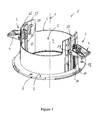
- Figure 1 shows a fixing system 1 for recessed luminaires in a perspective view.
- Figure 2 shows an exploded view of the same fixing system 1.
- the fixing system 1 has a carrier frame 2 and a clamping unit 3 connected to the carrier frame 2.
- the fixing system 1 is designed for recessed luminaires which are mounted to a ceiling. E. g., a LED light can be mounted to the fixing system 1.
- the carrier frame 2 comprises a cylindrical surface section 4 which defines a recessed opening 5 for mounting the luminaire to the carrier frame 2.
- the cylindrical surface section 4 is oriented coaxial to a center axle 6 of the carrier frame 2.
- the carrier frame 2 also comprises a flat rim section 7 which protrudes from the cylindrical surface section 4 radially to the outside.
- the flat rim section 7 provides a first contact surface 8 of the fixing system 1 which is built as a plane contact surface.
- the contact surface 8 is designed for connecting the fixing system 1 to an outer side of the ceiling.
- the clamping unit 3 comprises a flap 9, a nut 10 and a screw 11.
- the flap 9 is the clamping element of the clamping unit 10.
- the flap 9 has a second contact surface 12 and a control surface 13 which is designed for interaction with a control edge 14 of the carrier frame 2. The interaction will be described later in detail.
- the flap 9 is L-shaped with a first arm 21 comprising the control surface 13 and with a second arm 22 comprising the second contact surface 12.
- the nut 10 has two bearing pins 15 protruding from a thread section 16 of the nut 10.
- the bearing pins 15 are mounted in two recesses 17 of the flap 9.
- the nut 10 is therefore rotatable arranged to the flap 9.
- the screw 11 meshes with the nut 10.
- the screw 11 comprises a screw head 18 and a shaft 19 which extends in parallel to the center axle 6 of the cylindrical surface section 4 and the carrier frame 2.
- the flat rim section 7 of the carrier frame 2 provides a hole 20 for the screw 11.
- a diameter of the hole 20 is smaller than a diameter of the screw head 18 and taller than a diameter of the shaft 19 of the screw 11.
- the hole 20 is positioned next to the cylindrical surface section 4 of the carrier frame 2.
- the nut 10 has a guiding lug 23 which interacts with and translatory travels in a sliding rail 24 of the carrier frame 2 when mounting the carrier frame 2 to the ceiling.
- the sliding rail 24 is part of the cylindrical surface section 4 and extends in parallel to the center axle 6. Guiding lug 23 and sliding rail 24 are designed for smooth and exact movement of the nut 10 and prevent the clamping unit 3 from misalignment.
- grooves 25 and guiding rails 26 are provided on both sides of the sliding rail 24 .
- the two grooves 25 as well as the guiding rails 26 extend in parallel to the center axles 6.
- the lower front sides 28 of the grooves 25 define the control edge 14 which interact with the control surface 13 of the flap 9.
- the two guiding rails 26 interact with two guiding surfaces 27 of the flap 9.
- the guiding surfaces 27 are installed next to the control surface 13 on the first arm 31 of the flap 9. Control surface 13 and guiding surface 27 are in a rectangular orientation to each other.
- the fixing system 1 has identical two clamping units 3 which are connected to the carrier frame 2 on opposite sides of the center axle 6.
- the two clamping units 3 allow a secure fastening of the fixing system 1.
- FIG. 1 the installation process of the fixing system 1 is illustrated.
- the flaps 9 are in upright position with the second contact surfaces 12 being tangential oriented to the cylindrical surface section 4 of the carrier frame 2.
- This upright position of the flaps 9 define an installation position of the clamping unit 3 in which the fixing system 1 is pushed into a mounting hole 29 of a ceiling 30 to which the fixing system is mounted.
- the luminaire 31 is located in the recessed opening 5 of the carrier frame 2 and mounted to the fixing system 1. Therefore the fixing system 1 allows one step installation process with a combined installation of fixing system 1 and luminaire 31.
- the screws 11 are rotated in the opposite direction causing the flaps 9 to move from the mounting position to the installation position.
- the fixing system 1 including the recessed luminaire 31 can be removed from the ceiling 30.
Landscapes
- Engineering & Computer Science (AREA)
- General Engineering & Computer Science (AREA)
- Non-Portable Lighting Devices Or Systems Thereof (AREA)
Priority Applications (1)
| Application Number | Priority Date | Filing Date | Title |
|---|---|---|---|
| EP12197782.1A EP2746643B1 (de) | 2012-12-18 | 2012-12-18 | Befestigungssystem für Einbauleuchte |
Applications Claiming Priority (1)
| Application Number | Priority Date | Filing Date | Title |
|---|---|---|---|
| EP12197782.1A EP2746643B1 (de) | 2012-12-18 | 2012-12-18 | Befestigungssystem für Einbauleuchte |
Publications (2)
| Publication Number | Publication Date |
|---|---|
| EP2746643A1 true EP2746643A1 (de) | 2014-06-25 |
| EP2746643B1 EP2746643B1 (de) | 2017-09-06 |
Family
ID=47559144
Family Applications (1)
| Application Number | Title | Priority Date | Filing Date |
|---|---|---|---|
| EP12197782.1A Not-in-force EP2746643B1 (de) | 2012-12-18 | 2012-12-18 | Befestigungssystem für Einbauleuchte |
Country Status (1)
| Country | Link |
|---|---|
| EP (1) | EP2746643B1 (de) |
Cited By (4)
| Publication number | Priority date | Publication date | Assignee | Title |
|---|---|---|---|---|
| DE102014205901A1 (de) * | 2014-03-28 | 2015-10-01 | H4X E.U. | Leuchte |
| CN105972532A (zh) * | 2015-03-11 | 2016-09-28 | 松下知识产权经营株式会社 | 照明装置、移动体以及支撑体 |
| US10222013B2 (en) | 2014-07-10 | 2019-03-05 | H4X E.U. | Luminaire, assembly for a grid ceiling, method for installing a luminaire, method for removing a luminaire, and removal tool |
| WO2021051159A1 (en) * | 2019-09-17 | 2021-03-25 | Spa Electrics Pty Ltd | Adapter assembly for luminaire |
Families Citing this family (1)
| Publication number | Priority date | Publication date | Assignee | Title |
|---|---|---|---|---|
| US11076211B2 (en) | 2019-06-12 | 2021-07-27 | Swarm Holdings Llc. | Mount assembly and speaker mount with screwless dog |
Citations (7)
| Publication number | Priority date | Publication date | Assignee | Title |
|---|---|---|---|---|
| GB832921A (en) * | 1957-01-31 | 1960-04-21 | Gen Electric Co Ltd | Improvements in or relating to electric lighting fittings |
| US5377088A (en) | 1993-03-03 | 1994-12-27 | Lecluze; Michel | Light fixture for mounting to a ceiling, wall or the like |
| CA2577753A1 (en) | 2006-02-17 | 2007-08-17 | Canlyte Inc. | Recessed lighting fixture |
| US20080186718A1 (en) | 2007-02-07 | 2008-08-07 | Antonio Magisano | Recessed Light Can Height Adjustment |
| US20100252703A1 (en) * | 2009-04-06 | 2010-10-07 | Wright Doug S | Speaker assemblies, methods of installing speaker assemblies and methods of making speaker assemblies |
| EP2320136A1 (de) | 2009-11-05 | 2011-05-11 | Siteco Beleuchtungstechnik GmbH | Einbaurahmen mit Befestigungsvorrichtung |
| DE102009057443A1 (de) * | 2009-12-08 | 2011-06-09 | Traxon Technologies Ltd. | Einbauleuchte und Anordnung mit einer Einbauleuchte |
-
2012
- 2012-12-18 EP EP12197782.1A patent/EP2746643B1/de not_active Not-in-force
Patent Citations (7)
| Publication number | Priority date | Publication date | Assignee | Title |
|---|---|---|---|---|
| GB832921A (en) * | 1957-01-31 | 1960-04-21 | Gen Electric Co Ltd | Improvements in or relating to electric lighting fittings |
| US5377088A (en) | 1993-03-03 | 1994-12-27 | Lecluze; Michel | Light fixture for mounting to a ceiling, wall or the like |
| CA2577753A1 (en) | 2006-02-17 | 2007-08-17 | Canlyte Inc. | Recessed lighting fixture |
| US20080186718A1 (en) | 2007-02-07 | 2008-08-07 | Antonio Magisano | Recessed Light Can Height Adjustment |
| US20100252703A1 (en) * | 2009-04-06 | 2010-10-07 | Wright Doug S | Speaker assemblies, methods of installing speaker assemblies and methods of making speaker assemblies |
| EP2320136A1 (de) | 2009-11-05 | 2011-05-11 | Siteco Beleuchtungstechnik GmbH | Einbaurahmen mit Befestigungsvorrichtung |
| DE102009057443A1 (de) * | 2009-12-08 | 2011-06-09 | Traxon Technologies Ltd. | Einbauleuchte und Anordnung mit einer Einbauleuchte |
Cited By (8)
| Publication number | Priority date | Publication date | Assignee | Title |
|---|---|---|---|---|
| DE102014205901A1 (de) * | 2014-03-28 | 2015-10-01 | H4X E.U. | Leuchte |
| DE102014205901B4 (de) * | 2014-03-28 | 2019-05-23 | H4X E.U. | Leuchte |
| US10222013B2 (en) | 2014-07-10 | 2019-03-05 | H4X E.U. | Luminaire, assembly for a grid ceiling, method for installing a luminaire, method for removing a luminaire, and removal tool |
| CN105972532A (zh) * | 2015-03-11 | 2016-09-28 | 松下知识产权经营株式会社 | 照明装置、移动体以及支撑体 |
| WO2021051159A1 (en) * | 2019-09-17 | 2021-03-25 | Spa Electrics Pty Ltd | Adapter assembly for luminaire |
| US11746996B2 (en) | 2019-09-17 | 2023-09-05 | Spa Electrics Pty Ltd | Adapter assembly for luminaire |
| EP4031809A4 (de) * | 2019-09-17 | 2023-09-27 | SPA Electrics Pty Ltd | Adapteranordnung für leuchte |
| AU2020351585B2 (en) * | 2019-09-17 | 2024-08-22 | Spa Electrics Pty Ltd | Adapter assembly for luminaire |
Also Published As
| Publication number | Publication date |
|---|---|
| EP2746643B1 (de) | 2017-09-06 |
Similar Documents
| Publication | Publication Date | Title |
|---|---|---|
| EP2746643B1 (de) | Befestigungssystem für Einbauleuchte | |
| US10030727B2 (en) | Electro-mechanical brake device | |
| US11761520B2 (en) | Linear drive device, motor, and linear drive device production method | |
| US7443121B2 (en) | Actuator control system | |
| US8875348B2 (en) | Friction hinge system | |
| KR101911459B1 (ko) | 자동차를 위한 액추에이팅 드라이브 | |
| US11041551B2 (en) | Pivotable spindle nut | |
| US8256728B2 (en) | Speaker assemblies, methods of installing speaker assemblies and methods of making speaker assemblies | |
| EP2933055A1 (de) | Schraubenanordnung und transportvorrichtung damit | |
| JP6484764B2 (ja) | 調節式圧力解放掛け金 | |
| JP2017517861A5 (de) | ||
| WO2013009608A1 (en) | Limit switch assembly | |
| US20180372149A1 (en) | Fixing member, self-aligning bearing mechanism, actuator, and lamp | |
| CN110832218A (zh) | 能够电磁操纵的弹簧力制动器和驱动系统 | |
| CN105531150A (zh) | 用于将照明和/或信号指示模块固定到结构元件的装置 | |
| US10197138B2 (en) | Drive apparatus | |
| EP2791550B1 (de) | Antirassel zahnrad, getriebezug mit einem derartigen antirassel zahnrad, und motor versehen mit einem derartigen zahnrad | |
| CN221329311U (zh) | 楔块调节机构 | |
| CN104416528B (zh) | 用于安装传动机构‑驱动单元的方法、用于实施方法的定心元件以及传动机构‑驱动单元 | |
| CN102198859B (zh) | 用于机舱内部组件的装配装置 | |
| CN113613950A (zh) | 发光单元的光模块的保持装置、光模块和车辆的发光单元 | |
| EP2601709B1 (de) | Antirückschlagvorrichtung | |
| CN103438406A (zh) | 一种舞台灯具光闸旋转结构 | |
| TWI765614B (zh) | 可變距的上下料機構 | |
| CN116557375B (zh) | 一种气缸装置及半导体设备 |
Legal Events
| Date | Code | Title | Description |
|---|---|---|---|
| PUAI | Public reference made under article 153(3) epc to a published international application that has entered the european phase |
Free format text: ORIGINAL CODE: 0009012 |
|
| 17P | Request for examination filed |
Effective date: 20121218 |
|
| AK | Designated contracting states |
Kind code of ref document: A1 Designated state(s): AL AT BE BG CH CY CZ DE DK EE ES FI FR GB GR HR HU IE IS IT LI LT LU LV MC MK MT NL NO PL PT RO RS SE SI SK SM TR |
|
| AX | Request for extension of the european patent |
Extension state: BA ME |
|
| R17P | Request for examination filed (corrected) |
Effective date: 20140729 |
|
| RBV | Designated contracting states (corrected) |
Designated state(s): AL AT BE BG CH CY CZ DE DK EE ES FI FR GB GR HR HU IE IS IT LI LT LU LV MC MK MT NL NO PL PT RO RS SE SI SK SM TR |
|
| RIC1 | Information provided on ipc code assigned before grant |
Ipc: F21V 21/04 20060101ALI20170303BHEP Ipc: F21S 8/02 20060101AFI20170303BHEP |
|
| GRAP | Despatch of communication of intention to grant a patent |
Free format text: ORIGINAL CODE: EPIDOSNIGR1 |
|
| INTG | Intention to grant announced |
Effective date: 20170517 |
|
| GRAS | Grant fee paid |
Free format text: ORIGINAL CODE: EPIDOSNIGR3 |
|
| GRAA | (expected) grant |
Free format text: ORIGINAL CODE: 0009210 |
|
| AK | Designated contracting states |
Kind code of ref document: B1 Designated state(s): AL AT BE BG CH CY CZ DE DK EE ES FI FR GB GR HR HU IE IS IT LI LT LU LV MC MK MT NL NO PL PT RO RS SE SI SK SM TR |
|
| REG | Reference to a national code |
Ref country code: GB Ref legal event code: FG4D |
|
| REG | Reference to a national code |
Ref country code: CH Ref legal event code: EP Ref country code: AT Ref legal event code: REF Ref document number: 926283 Country of ref document: AT Kind code of ref document: T Effective date: 20170915 |
|
| REG | Reference to a national code |
Ref country code: IE Ref legal event code: FG4D |
|
| REG | Reference to a national code |
Ref country code: DE Ref legal event code: R096 Ref document number: 602012036871 Country of ref document: DE |
|
| REG | Reference to a national code |
Ref country code: FR Ref legal event code: PLFP Year of fee payment: 6 |
|
| REG | Reference to a national code |
Ref country code: DE Ref legal event code: R081 Ref document number: 602012036871 Country of ref document: DE Owner name: HELLA GMBH & CO. KGAA, DE Free format text: FORMER OWNER: HELLA KGAA HUECK & CO., 59557 LIPPSTADT, DE |
|
| RAP2 | Party data changed (patent owner data changed or rights of a patent transferred) |
Owner name: HELLA GMBH & CO. KGAA |
|
| REG | Reference to a national code |
Ref country code: NL Ref legal event code: MP Effective date: 20170906 |
|
| REG | Reference to a national code |
Ref country code: LT Ref legal event code: MG4D |
|
| PG25 | Lapsed in a contracting state [announced via postgrant information from national office to epo] |
Ref country code: HR Free format text: LAPSE BECAUSE OF FAILURE TO SUBMIT A TRANSLATION OF THE DESCRIPTION OR TO PAY THE FEE WITHIN THE PRESCRIBED TIME-LIMIT Effective date: 20170906 Ref country code: LT Free format text: LAPSE BECAUSE OF FAILURE TO SUBMIT A TRANSLATION OF THE DESCRIPTION OR TO PAY THE FEE WITHIN THE PRESCRIBED TIME-LIMIT Effective date: 20170906 Ref country code: NO Free format text: LAPSE BECAUSE OF FAILURE TO SUBMIT A TRANSLATION OF THE DESCRIPTION OR TO PAY THE FEE WITHIN THE PRESCRIBED TIME-LIMIT Effective date: 20171206 Ref country code: FI Free format text: LAPSE BECAUSE OF FAILURE TO SUBMIT A TRANSLATION OF THE DESCRIPTION OR TO PAY THE FEE WITHIN THE PRESCRIBED TIME-LIMIT Effective date: 20170906 Ref country code: SE Free format text: LAPSE BECAUSE OF FAILURE TO SUBMIT A TRANSLATION OF THE DESCRIPTION OR TO PAY THE FEE WITHIN THE PRESCRIBED TIME-LIMIT Effective date: 20170906 |
|
| REG | Reference to a national code |
Ref country code: AT Ref legal event code: MK05 Ref document number: 926283 Country of ref document: AT Kind code of ref document: T Effective date: 20170906 |
|
| PG25 | Lapsed in a contracting state [announced via postgrant information from national office to epo] |
Ref country code: ES Free format text: LAPSE BECAUSE OF FAILURE TO SUBMIT A TRANSLATION OF THE DESCRIPTION OR TO PAY THE FEE WITHIN THE PRESCRIBED TIME-LIMIT Effective date: 20170906 Ref country code: BG Free format text: LAPSE BECAUSE OF FAILURE TO SUBMIT A TRANSLATION OF THE DESCRIPTION OR TO PAY THE FEE WITHIN THE PRESCRIBED TIME-LIMIT Effective date: 20171206 Ref country code: LV Free format text: LAPSE BECAUSE OF FAILURE TO SUBMIT A TRANSLATION OF THE DESCRIPTION OR TO PAY THE FEE WITHIN THE PRESCRIBED TIME-LIMIT Effective date: 20170906 Ref country code: RS Free format text: LAPSE BECAUSE OF FAILURE TO SUBMIT A TRANSLATION OF THE DESCRIPTION OR TO PAY THE FEE WITHIN THE PRESCRIBED TIME-LIMIT Effective date: 20170906 Ref country code: GR Free format text: LAPSE BECAUSE OF FAILURE TO SUBMIT A TRANSLATION OF THE DESCRIPTION OR TO PAY THE FEE WITHIN THE PRESCRIBED TIME-LIMIT Effective date: 20171207 |
|
| PG25 | Lapsed in a contracting state [announced via postgrant information from national office to epo] |
Ref country code: NL Free format text: LAPSE BECAUSE OF FAILURE TO SUBMIT A TRANSLATION OF THE DESCRIPTION OR TO PAY THE FEE WITHIN THE PRESCRIBED TIME-LIMIT Effective date: 20170906 |
|
| PG25 | Lapsed in a contracting state [announced via postgrant information from national office to epo] |
Ref country code: RO Free format text: LAPSE BECAUSE OF FAILURE TO SUBMIT A TRANSLATION OF THE DESCRIPTION OR TO PAY THE FEE WITHIN THE PRESCRIBED TIME-LIMIT Effective date: 20170906 Ref country code: PL Free format text: LAPSE BECAUSE OF FAILURE TO SUBMIT A TRANSLATION OF THE DESCRIPTION OR TO PAY THE FEE WITHIN THE PRESCRIBED TIME-LIMIT Effective date: 20170906 Ref country code: CZ Free format text: LAPSE BECAUSE OF FAILURE TO SUBMIT A TRANSLATION OF THE DESCRIPTION OR TO PAY THE FEE WITHIN THE PRESCRIBED TIME-LIMIT Effective date: 20170906 |
|
| PG25 | Lapsed in a contracting state [announced via postgrant information from national office to epo] |
Ref country code: SK Free format text: LAPSE BECAUSE OF FAILURE TO SUBMIT A TRANSLATION OF THE DESCRIPTION OR TO PAY THE FEE WITHIN THE PRESCRIBED TIME-LIMIT Effective date: 20170906 Ref country code: SM Free format text: LAPSE BECAUSE OF FAILURE TO SUBMIT A TRANSLATION OF THE DESCRIPTION OR TO PAY THE FEE WITHIN THE PRESCRIBED TIME-LIMIT Effective date: 20170906 Ref country code: IT Free format text: LAPSE BECAUSE OF FAILURE TO SUBMIT A TRANSLATION OF THE DESCRIPTION OR TO PAY THE FEE WITHIN THE PRESCRIBED TIME-LIMIT Effective date: 20170906 Ref country code: EE Free format text: LAPSE BECAUSE OF FAILURE TO SUBMIT A TRANSLATION OF THE DESCRIPTION OR TO PAY THE FEE WITHIN THE PRESCRIBED TIME-LIMIT Effective date: 20170906 Ref country code: IS Free format text: LAPSE BECAUSE OF FAILURE TO SUBMIT A TRANSLATION OF THE DESCRIPTION OR TO PAY THE FEE WITHIN THE PRESCRIBED TIME-LIMIT Effective date: 20180106 Ref country code: AT Free format text: LAPSE BECAUSE OF FAILURE TO SUBMIT A TRANSLATION OF THE DESCRIPTION OR TO PAY THE FEE WITHIN THE PRESCRIBED TIME-LIMIT Effective date: 20170906 |
|
| REG | Reference to a national code |
Ref country code: DE Ref legal event code: R097 Ref document number: 602012036871 Country of ref document: DE |
|
| PLBE | No opposition filed within time limit |
Free format text: ORIGINAL CODE: 0009261 |
|
| STAA | Information on the status of an ep patent application or granted ep patent |
Free format text: STATUS: NO OPPOSITION FILED WITHIN TIME LIMIT |
|
| PG25 | Lapsed in a contracting state [announced via postgrant information from national office to epo] |
Ref country code: DK Free format text: LAPSE BECAUSE OF FAILURE TO SUBMIT A TRANSLATION OF THE DESCRIPTION OR TO PAY THE FEE WITHIN THE PRESCRIBED TIME-LIMIT Effective date: 20170906 |
|
| REG | Reference to a national code |
Ref country code: CH Ref legal event code: PL |
|
| 26N | No opposition filed |
Effective date: 20180607 |
|
| PG25 | Lapsed in a contracting state [announced via postgrant information from national office to epo] |
Ref country code: SI Free format text: LAPSE BECAUSE OF FAILURE TO SUBMIT A TRANSLATION OF THE DESCRIPTION OR TO PAY THE FEE WITHIN THE PRESCRIBED TIME-LIMIT Effective date: 20170906 |
|
| REG | Reference to a national code |
Ref country code: IE Ref legal event code: MM4A |
|
| PG25 | Lapsed in a contracting state [announced via postgrant information from national office to epo] |
Ref country code: MT Free format text: LAPSE BECAUSE OF NON-PAYMENT OF DUE FEES Effective date: 20171218 Ref country code: LU Free format text: LAPSE BECAUSE OF NON-PAYMENT OF DUE FEES Effective date: 20171218 |
|
| REG | Reference to a national code |
Ref country code: BE Ref legal event code: MM Effective date: 20171231 |
|
| PG25 | Lapsed in a contracting state [announced via postgrant information from national office to epo] |
Ref country code: IE Free format text: LAPSE BECAUSE OF NON-PAYMENT OF DUE FEES Effective date: 20171218 |
|
| PG25 | Lapsed in a contracting state [announced via postgrant information from national office to epo] |
Ref country code: BE Free format text: LAPSE BECAUSE OF NON-PAYMENT OF DUE FEES Effective date: 20171231 Ref country code: LI Free format text: LAPSE BECAUSE OF NON-PAYMENT OF DUE FEES Effective date: 20171231 Ref country code: CH Free format text: LAPSE BECAUSE OF NON-PAYMENT OF DUE FEES Effective date: 20171231 |
|
| PG25 | Lapsed in a contracting state [announced via postgrant information from national office to epo] |
Ref country code: MC Free format text: LAPSE BECAUSE OF FAILURE TO SUBMIT A TRANSLATION OF THE DESCRIPTION OR TO PAY THE FEE WITHIN THE PRESCRIBED TIME-LIMIT Effective date: 20170906 Ref country code: HU Free format text: LAPSE BECAUSE OF FAILURE TO SUBMIT A TRANSLATION OF THE DESCRIPTION OR TO PAY THE FEE WITHIN THE PRESCRIBED TIME-LIMIT; INVALID AB INITIO Effective date: 20121218 |
|
| PG25 | Lapsed in a contracting state [announced via postgrant information from national office to epo] |
Ref country code: CY Free format text: LAPSE BECAUSE OF NON-PAYMENT OF DUE FEES Effective date: 20170906 |
|
| PG25 | Lapsed in a contracting state [announced via postgrant information from national office to epo] |
Ref country code: MK Free format text: LAPSE BECAUSE OF FAILURE TO SUBMIT A TRANSLATION OF THE DESCRIPTION OR TO PAY THE FEE WITHIN THE PRESCRIBED TIME-LIMIT Effective date: 20170906 |
|
| PG25 | Lapsed in a contracting state [announced via postgrant information from national office to epo] |
Ref country code: TR Free format text: LAPSE BECAUSE OF FAILURE TO SUBMIT A TRANSLATION OF THE DESCRIPTION OR TO PAY THE FEE WITHIN THE PRESCRIBED TIME-LIMIT Effective date: 20170906 |
|
| PG25 | Lapsed in a contracting state [announced via postgrant information from national office to epo] |
Ref country code: PT Free format text: LAPSE BECAUSE OF FAILURE TO SUBMIT A TRANSLATION OF THE DESCRIPTION OR TO PAY THE FEE WITHIN THE PRESCRIBED TIME-LIMIT Effective date: 20170906 |
|
| PG25 | Lapsed in a contracting state [announced via postgrant information from national office to epo] |
Ref country code: AL Free format text: LAPSE BECAUSE OF FAILURE TO SUBMIT A TRANSLATION OF THE DESCRIPTION OR TO PAY THE FEE WITHIN THE PRESCRIBED TIME-LIMIT Effective date: 20170906 |
|
| PGFP | Annual fee paid to national office [announced via postgrant information from national office to epo] |
Ref country code: FR Payment date: 20221010 Year of fee payment: 11 |
|
| PGFP | Annual fee paid to national office [announced via postgrant information from national office to epo] |
Ref country code: GB Payment date: 20221027 Year of fee payment: 11 Ref country code: DE Payment date: 20220622 Year of fee payment: 11 |
|
| REG | Reference to a national code |
Ref country code: DE Ref legal event code: R119 Ref document number: 602012036871 Country of ref document: DE |
|
| GBPC | Gb: european patent ceased through non-payment of renewal fee |
Effective date: 20231218 |
|
| PG25 | Lapsed in a contracting state [announced via postgrant information from national office to epo] |
Ref country code: DE Free format text: LAPSE BECAUSE OF NON-PAYMENT OF DUE FEES Effective date: 20240702 |
|
| PG25 | Lapsed in a contracting state [announced via postgrant information from national office to epo] |
Ref country code: GB Free format text: LAPSE BECAUSE OF NON-PAYMENT OF DUE FEES Effective date: 20231218 |
|
| PG25 | Lapsed in a contracting state [announced via postgrant information from national office to epo] |
Ref country code: FR Free format text: LAPSE BECAUSE OF NON-PAYMENT OF DUE FEES Effective date: 20231231 |
|
| PG25 | Lapsed in a contracting state [announced via postgrant information from national office to epo] |
Ref country code: GB Free format text: LAPSE BECAUSE OF NON-PAYMENT OF DUE FEES Effective date: 20231218 Ref country code: FR Free format text: LAPSE BECAUSE OF NON-PAYMENT OF DUE FEES Effective date: 20231231 Ref country code: DE Free format text: LAPSE BECAUSE OF NON-PAYMENT OF DUE FEES Effective date: 20240702 |