EP2746696B1 - Dispositif de fixation de modules solaires sur un profil de support - Google Patents
Dispositif de fixation de modules solaires sur un profil de support Download PDFInfo
- Publication number
- EP2746696B1 EP2746696B1 EP13193669.2A EP13193669A EP2746696B1 EP 2746696 B1 EP2746696 B1 EP 2746696B1 EP 13193669 A EP13193669 A EP 13193669A EP 2746696 B1 EP2746696 B1 EP 2746696B1
- Authority
- EP
- European Patent Office
- Prior art keywords
- cover plate
- holding profile
- edge
- profile
- foot
- Prior art date
- Legal status (The legal status is an assumption and is not a legal conclusion. Google has not performed a legal analysis and makes no representation as to the accuracy of the status listed.)
- Active
Links
Images

Classifications
-
- F—MECHANICAL ENGINEERING; LIGHTING; HEATING; WEAPONS; BLASTING
- F24—HEATING; RANGES; VENTILATING
- F24S—SOLAR HEAT COLLECTORS; SOLAR HEAT SYSTEMS
- F24S25/00—Arrangement of stationary mountings or supports for solar heat collector modules
- F24S25/60—Fixation means, e.g. fasteners, specially adapted for supporting solar heat collector modules
- F24S25/63—Fixation means, e.g. fasteners, specially adapted for supporting solar heat collector modules for fixing modules or their peripheral frames to supporting elements
- F24S25/634—Clamps; Clips
-
- F—MECHANICAL ENGINEERING; LIGHTING; HEATING; WEAPONS; BLASTING
- F24—HEATING; RANGES; VENTILATING
- F24S—SOLAR HEAT COLLECTORS; SOLAR HEAT SYSTEMS
- F24S25/00—Arrangement of stationary mountings or supports for solar heat collector modules
- F24S25/60—Fixation means, e.g. fasteners, specially adapted for supporting solar heat collector modules
- F24S25/63—Fixation means, e.g. fasteners, specially adapted for supporting solar heat collector modules for fixing modules or their peripheral frames to supporting elements
- F24S25/632—Side connectors; Base connectors
-
- F—MECHANICAL ENGINEERING; LIGHTING; HEATING; WEAPONS; BLASTING
- F24—HEATING; RANGES; VENTILATING
- F24S—SOLAR HEAT COLLECTORS; SOLAR HEAT SYSTEMS
- F24S25/00—Arrangement of stationary mountings or supports for solar heat collector modules
- F24S25/60—Fixation means, e.g. fasteners, specially adapted for supporting solar heat collector modules
- F24S2025/6007—Fixation means, e.g. fasteners, specially adapted for supporting solar heat collector modules by using form-fitting connection means, e.g. tongue and groove
-
- F—MECHANICAL ENGINEERING; LIGHTING; HEATING; WEAPONS; BLASTING
- F24—HEATING; RANGES; VENTILATING
- F24S—SOLAR HEAT COLLECTORS; SOLAR HEAT SYSTEMS
- F24S25/00—Arrangement of stationary mountings or supports for solar heat collector modules
- F24S25/60—Fixation means, e.g. fasteners, specially adapted for supporting solar heat collector modules
- F24S2025/6009—Fixation means, e.g. fasteners, specially adapted for supporting solar heat collector modules by deforming the material, e.g. by crimping or clinching
-
- Y—GENERAL TAGGING OF NEW TECHNOLOGICAL DEVELOPMENTS; GENERAL TAGGING OF CROSS-SECTIONAL TECHNOLOGIES SPANNING OVER SEVERAL SECTIONS OF THE IPC; TECHNICAL SUBJECTS COVERED BY FORMER USPC CROSS-REFERENCE ART COLLECTIONS [XRACs] AND DIGESTS
- Y02—TECHNOLOGIES OR APPLICATIONS FOR MITIGATION OR ADAPTATION AGAINST CLIMATE CHANGE
- Y02E—REDUCTION OF GREENHOUSE GAS [GHG] EMISSIONS, RELATED TO ENERGY GENERATION, TRANSMISSION OR DISTRIBUTION
- Y02E10/00—Energy generation through renewable energy sources
- Y02E10/40—Solar thermal energy, e.g. solar towers
- Y02E10/47—Mountings or tracking
Definitions
- the invention relates to a device for fastening solar modules to a support profile according to the preamble of claim 1.
- the document DE 20 2011 003 490 U1 describes a device for fastening solar modules according to the preamble of claim 1.
- the invention has for its object to provide a device of the type mentioned, which is characterized by a high stability by a relatively simple and inexpensive production.
- Fig. 1 shows in a perspective view of an embodiment of a device according to the invention, which is made in one piece in a punch-bending process of a metal sheet.
- the embodiment according to Fig. 1 has an S-like trained, elongated and extending in a transverse direction holding profile 1, which in this embodiment by a cover portion 2, by a connected to the cover 2 and aligned at right angles to the cover section 2 deck-side Edge portion 3, by a connected to the top-side edge portion 3, perpendicular to the top-side edge portion 3 and parallel to the cover portion 2 aligned central support portion 4, by a connected to the central support portion 4 and aligned at right angles to the central support portion 4 foot-side edge portion 5 and through a connected to the foot-side edge portion 5, perpendicular to the foot-side edge portion 5 and the deck-side edge portion 3 and parallel to the central support portion 4 and the cover portion 2 aligned two-part foot-side support portion 6 is formed.
- Fig. 1 a U-shaped trained mounting foot 7, which has a flat cover plate 8 as the base of the U, which is trapezoidal designed and connected with its long base edge side 9 with the foot-side edge portion 5.
- Fig. 1 The representation according to Fig. 1 can be seen that in the foot-side edge portion 5 and in the cover plate 8 are on both sides of the base edge side 9 extending Versteifungsver Weggungen 10 are formed to increase the bending stiffness of the mounting foot 7 and the support profile 1 with respect to each other against a simple fold along the base edge side 9.
- an edge recess 12 is introduced, which closes each foot-side support portion 6 relative to the mounting foot 7 and the mounting foot 7 facing boundary formed by a three-dimensionally curved transition section 13 is.
- each side plate 14 of the mounting foot 7 is integrally formed, each side plate 14 having an associated with the cover plate 8, from obliquely formed and formed from two mutually angled segments intermediate portion 15 and a planar edge portion 16.
- the segments of the intermediate sections 15 are designed so that the edge portions 16 are aligned substantially parallel to each other.
- a short edge web 17 facing away from the holding profile 1 and a long edge web 18 facing the holding profile 1 are folded in order to increase the flexural rigidity of the side plates 14 in relation to a completely planar design.
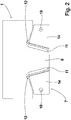
- Fig. 2 shows in a plan view a blank for the embodiment according to Fig. 1 after performing the punching operation and before performing the bending process.
- Fig. 2 are between the material provided for the cover plate 8 and the material provided for the side plates 14 with solid straight lines the Abkantlinien for bending the side plates 14 of the cover plate 8 to form the Schenkelrandtreatment 11 shown, while with broken curved lines that for forming the three-dimensional curved transition portions 13 between the edge recesses 12 and the leg edge sides 11th forcibly resulting bending lines are shown.
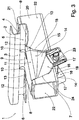
- Fig. 3 shows in a perspective view of the embodiment according to Fig. 1 in a final assembly arrangement connected to a carrier profile 20.
- the cover plate 8 is located on a top surface 21 of the carrier profile 20, while the side plates 14 include with their edge portions 16 adjoining the top surface 21 side surfaces 22 of the carrier profile 20.
- the edge portions 16 with a certain tension connecting fastener 23 is performed so that the retaining profile 1 is connected to the carrier profile 20.
- the fastening means 23 engages behind a cover surface 21 opposite, connected to the side surfaces 22 foot surface 24 of the carrier profile 20th
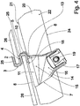
- Fig. 4 shows a side view of the embodiment according to Fig. 1 in the final assembly according to Fig. 3 , Out Fig. 4 is clearly seen that the edge portions 16 of the side plates 14 are angled in the direction of the holding profile 1 by the angling of the segments of the intermediate portions 15, so that the fürsteckausEnglishept 19 relative to a relative to the cover plate 8 rectangular orientation of the edge portions 16 to the support section 1 out are offset. As a result, the distance between the fürsteckausEnglishisme 19 and the retaining profile 1 and thus the leverage of acting on the retaining profile 1 forces is reduced.
- the solar modules 26 are connected to the carrier profile 20.
Landscapes
- Engineering & Computer Science (AREA)
- Physics & Mathematics (AREA)
- Life Sciences & Earth Sciences (AREA)
- Sustainable Development (AREA)
- Sustainable Energy (AREA)
- Thermal Sciences (AREA)
- Chemical & Material Sciences (AREA)
- Combustion & Propulsion (AREA)
- Mechanical Engineering (AREA)
- General Engineering & Computer Science (AREA)
- Roof Covering Using Slabs Or Stiff Sheets (AREA)
- Photovoltaic Devices (AREA)
Claims (5)
- Dispositif pour assurer la fixation de modules solaires (26) sur un profilé porteur (20), comprenant un profilé de retenue (1), qui est configuré pour accueillir la bordure d'un côté d'au moins un module solaire (26), et comprenant également un pied de fixation (7) relié au profilé de retenue (1) et présentant une plaque de recouvrement (8) et au moins deux plaques latérales (14), qui sont reliées de manière fixe à la plaque de recouvrement (8) et s'étendent de manière à s'éloigner de cette plaque de recouvrement (8), le pied de fixation (7) étant d'une configuration en forme de U,
caractérisé en ce que le profilé de retenue (1) et le pied de fixation (7) constituent une pièce en tôle d'un seul tenant réalisée à partir d'une tôle métallique, en ce que le profilé de retenue (1) est formé au niveau de la bordure d'un côté de base (9) de la plaque de recouvrement (8), en ce qu'entre la plaque de recouvrement (8) et chaque plaque latérale (14), il est prévu un tronçon de liaison (11) courbe, et en ce que dans une zone de jointure entre chaque tronçon de liaison (11) et le profilé de retenue (1), il est prévu un tronçon de transition (13) à courbure en trois dimensions. - Dispositif selon la revendication 1, caractérisé en ce que la plaque de recouvrement (8) est d'une configuration de forme trapézoïdale, et est reliée par la bordure de son côté de grande longueur en tant que bordure de côté de base (9), au profilé de retenue (1).
- Dispositif selon la revendication 1 ou la revendication 2, caractérisé en ce que sur le côté de chaque tronçon de transition (13), qui est opposé à celui dirigé vers la plaque de recouvrement (8), il est prévu un évidement de bordure (12) se situant dans le plan de la plaque de recouvrement (8) et s'étendant vers l'intérieur du profilé de retenue (1).
- Dispositif selon l'une des revendications 1 à 3, caractérisé en ce qu'il est prévu au moins un estampage de renfort (10) s'étendant entre la plaque de recouvrement (8) et le profilé de retenue (1).
- Dispositif selon l'une des revendications 1 à 4, caractérisé en ce que des nervures de bordure (17, 18) sont coudées en saillie, au niveau des bordures des côtés des plaques latérales (14), qui s'étendent en s'éloignant de la plaque de recouvrement (8).
Applications Claiming Priority (1)
| Application Number | Priority Date | Filing Date | Title |
|---|---|---|---|
| DE102012223832.8A DE102012223832A1 (de) | 2012-12-19 | 2012-12-19 | Vorrichtung zum Befestigen von Solarmodulen an einem Trägerprofil |
Publications (3)
| Publication Number | Publication Date |
|---|---|
| EP2746696A2 EP2746696A2 (fr) | 2014-06-25 |
| EP2746696A3 EP2746696A3 (fr) | 2014-07-09 |
| EP2746696B1 true EP2746696B1 (fr) | 2019-02-27 |
Family
ID=49585326
Family Applications (1)
| Application Number | Title | Priority Date | Filing Date |
|---|---|---|---|
| EP13193669.2A Active EP2746696B1 (fr) | 2012-12-19 | 2013-11-20 | Dispositif de fixation de modules solaires sur un profil de support |
Country Status (2)
| Country | Link |
|---|---|
| EP (1) | EP2746696B1 (fr) |
| DE (1) | DE102012223832A1 (fr) |
Cited By (1)
| Publication number | Priority date | Publication date | Assignee | Title |
|---|---|---|---|---|
| US12088241B2 (en) | 2020-09-14 | 2024-09-10 | Array Tech, Inc. | Spring clip for photovoltaic module mounting |
Families Citing this family (1)
| Publication number | Priority date | Publication date | Assignee | Title |
|---|---|---|---|---|
| NL2023106B1 (en) * | 2019-05-10 | 2020-11-30 | Optixolar Holding B V | Coupling element between PV assembly and carrier frame |
Family Cites Families (3)
| Publication number | Priority date | Publication date | Assignee | Title |
|---|---|---|---|---|
| JPH10339008A (ja) * | 1997-06-06 | 1998-12-22 | Shiroki Corp | クリップ、太陽電池モジュール及び太陽電池モジュールの取り付け構造 |
| DE202008000997U1 (de) * | 2008-01-23 | 2008-05-15 | Solarpower Gmbh | Befestigungssystem |
| DE202011003490U1 (de) | 2011-03-04 | 2011-05-12 | Sodeik, Clemens | Halteklammer |
-
2012
- 2012-12-19 DE DE102012223832.8A patent/DE102012223832A1/de not_active Ceased
-
2013
- 2013-11-20 EP EP13193669.2A patent/EP2746696B1/fr active Active
Non-Patent Citations (1)
| Title |
|---|
| None * |
Cited By (1)
| Publication number | Priority date | Publication date | Assignee | Title |
|---|---|---|---|---|
| US12088241B2 (en) | 2020-09-14 | 2024-09-10 | Array Tech, Inc. | Spring clip for photovoltaic module mounting |
Also Published As
| Publication number | Publication date |
|---|---|
| DE102012223832A1 (de) | 2014-06-26 |
| EP2746696A3 (fr) | 2014-07-09 |
| EP2746696A2 (fr) | 2014-06-25 |
Similar Documents
| Publication | Publication Date | Title |
|---|---|---|
| EP2620720A1 (fr) | Clip pour former un élément de butée sur une surface | |
| DE102010008458A1 (de) | Befestigungsvorrichtung | |
| DE202012012485U1 (de) | Halter für ein Solarmodul | |
| WO2016096236A1 (fr) | Pièce de boîtier de batterie pour une batterie de traction d'un véhicule électrique ou hybride et boîtier de batterie | |
| DE102006017878A1 (de) | Befestigungsclip | |
| DE102013213995A1 (de) | Rückenlehne für einen Fahrzeugsitz und Fahrzeugsitz | |
| EP2790549B1 (fr) | Grille latérale | |
| DE102015219719A1 (de) | Faserverbundbauteil mit integriertem Anbindungssystem | |
| DE112010000777B4 (de) | Montageanordnung und Einsatz für ein Pedal oder dergleichen | |
| EP2746696B1 (fr) | Dispositif de fixation de modules solaires sur un profil de support | |
| DE102013210865B4 (de) | Vollständig in Eingriff stehende Gelenkanordnung | |
| DE102004054689A1 (de) | Befestigungsvorrichtung | |
| DE102010022472A1 (de) | Kantenschutzelement einer Klemme für ungerahmte PV-Module | |
| EP2425150B1 (fr) | Dispositif d'assemblage d'au moins deux courroies | |
| DE102007007514A1 (de) | Halteeinrichtung für eine Fahrzeugbatterie | |
| DE102017103595A1 (de) | Adapter und Verfahren zur Montage eines Schubkastens | |
| DE102015217463A1 (de) | Halter zur Befestigung an einem Strukturteil eines Kraftfahrzeuges sowie Anordnung eines Halters an einem Strukturteil eines Kraftfahrzeuges | |
| DE102014208303A1 (de) | Befestigungsvorrichtung zur Befestigung von Photovoltaikmodulen | |
| DE3047133C2 (de) | Vorrichtung zur lagesichernden Verbindung zweier Bauteile | |
| EP2731832B1 (fr) | Ensemble adaptateur de balai d'essuie-glace | |
| EP3221169B1 (fr) | Élément déflecteur pour un déflecteur d'air d'un véhicule à moteur | |
| DE102013104480A1 (de) | Garnitur und Deckelstab für eine textile Verarbeitungsmaschine | |
| DE102009018132B4 (de) | Halteklammer für Holzverpackungen und Verfahren zum Herstellen einer Halteklammer | |
| DE102009011993B4 (de) | Halter für ein Anzeigeelement | |
| DE102010028566A1 (de) | Solarmodultragvorrichtung |
Legal Events
| Date | Code | Title | Description |
|---|---|---|---|
| PUAL | Search report despatched |
Free format text: ORIGINAL CODE: 0009013 |
|
| PUAI | Public reference made under article 153(3) epc to a published international application that has entered the european phase |
Free format text: ORIGINAL CODE: 0009012 |
|
| 17P | Request for examination filed |
Effective date: 20131120 |
|
| AK | Designated contracting states |
Kind code of ref document: A2 Designated state(s): AL AT BE BG CH CY CZ DE DK EE ES FI FR GB GR HR HU IE IS IT LI LT LU LV MC MK MT NL NO PL PT RO RS SE SI SK SM TR |
|
| AX | Request for extension of the european patent |
Extension state: BA ME |
|
| AK | Designated contracting states |
Kind code of ref document: A3 Designated state(s): AL AT BE BG CH CY CZ DE DK EE ES FI FR GB GR HR HU IE IS IT LI LT LU LV MC MK MT NL NO PL PT RO RS SE SI SK SM TR |
|
| AX | Request for extension of the european patent |
Extension state: BA ME |
|
| RIC1 | Information provided on ipc code assigned before grant |
Ipc: F24J 2/52 20060101AFI20140605BHEP Ipc: F24J 2/00 20140101ALN20140605BHEP Ipc: F24J 2/46 20060101ALI20140605BHEP |
|
| R17P | Request for examination filed (corrected) |
Effective date: 20141114 |
|
| RBV | Designated contracting states (corrected) |
Designated state(s): AL AT BE BG CH CY CZ DE DK EE ES FI FR GB GR HR HU IE IS IT LI LT LU LV MC MK MT NL NO PL PT RO RS SE SI SK SM TR |
|
| RAP1 | Party data changed (applicant data changed or rights of an application transferred) |
Owner name: A. RAYMOND ET CIE |
|
| RIC1 | Information provided on ipc code assigned before grant |
Ipc: F24S 25/60 20180101ALI20180710BHEP Ipc: F24S 25/00 20180101ALN20180710BHEP Ipc: F24S 25/632 20180101AFI20180710BHEP Ipc: F24S 25/634 20180101ALI20180710BHEP |
|
| RIC1 | Information provided on ipc code assigned before grant |
Ipc: F24S 25/634 20180101ALI20180717BHEP Ipc: F24S 25/632 20180101AFI20180717BHEP Ipc: F24S 25/00 20180101ALN20180717BHEP Ipc: F24S 25/60 20180101ALI20180717BHEP |
|
| REG | Reference to a national code |
Ref country code: DE Ref legal event code: R079 Ref document number: 502013012282 Country of ref document: DE Free format text: PREVIOUS MAIN CLASS: F24J0002520000 Ipc: F24S0025632000 |
|
| GRAP | Despatch of communication of intention to grant a patent |
Free format text: ORIGINAL CODE: EPIDOSNIGR1 |
|
| STAA | Information on the status of an ep patent application or granted ep patent |
Free format text: STATUS: GRANT OF PATENT IS INTENDED |
|
| RIC1 | Information provided on ipc code assigned before grant |
Ipc: F24S 25/00 20180101ALN20180823BHEP Ipc: F24S 25/60 20180101ALI20180823BHEP Ipc: F24S 25/632 20180101AFI20180823BHEP Ipc: F24S 25/634 20180101ALI20180823BHEP |
|
| INTG | Intention to grant announced |
Effective date: 20180918 |
|
| GRAS | Grant fee paid |
Free format text: ORIGINAL CODE: EPIDOSNIGR3 |
|
| GRAA | (expected) grant |
Free format text: ORIGINAL CODE: 0009210 |
|
| STAA | Information on the status of an ep patent application or granted ep patent |
Free format text: STATUS: THE PATENT HAS BEEN GRANTED |
|
| AK | Designated contracting states |
Kind code of ref document: B1 Designated state(s): AL AT BE BG CH CY CZ DE DK EE ES FI FR GB GR HR HU IE IS IT LI LT LU LV MC MK MT NL NO PL PT RO RS SE SI SK SM TR |
|
| REG | Reference to a national code |
Ref country code: GB Ref legal event code: FG4D Free format text: NOT ENGLISH |
|
| REG | Reference to a national code |
Ref country code: CH Ref legal event code: EP |
|
| REG | Reference to a national code |
Ref country code: DE Ref legal event code: R096 Ref document number: 502013012282 Country of ref document: DE |
|
| REG | Reference to a national code |
Ref country code: AT Ref legal event code: REF Ref document number: 1101940 Country of ref document: AT Kind code of ref document: T Effective date: 20190315 |
|
| REG | Reference to a national code |
Ref country code: IE Ref legal event code: FG4D Free format text: LANGUAGE OF EP DOCUMENT: GERMAN |
|
| REG | Reference to a national code |
Ref country code: NL Ref legal event code: MP Effective date: 20190227 |
|
| REG | Reference to a national code |
Ref country code: LT Ref legal event code: MG4D |
|
| PG25 | Lapsed in a contracting state [announced via postgrant information from national office to epo] |
Ref country code: LT Free format text: LAPSE BECAUSE OF FAILURE TO SUBMIT A TRANSLATION OF THE DESCRIPTION OR TO PAY THE FEE WITHIN THE PRESCRIBED TIME-LIMIT Effective date: 20190227 Ref country code: NL Free format text: LAPSE BECAUSE OF FAILURE TO SUBMIT A TRANSLATION OF THE DESCRIPTION OR TO PAY THE FEE WITHIN THE PRESCRIBED TIME-LIMIT Effective date: 20190227 Ref country code: FI Free format text: LAPSE BECAUSE OF FAILURE TO SUBMIT A TRANSLATION OF THE DESCRIPTION OR TO PAY THE FEE WITHIN THE PRESCRIBED TIME-LIMIT Effective date: 20190227 Ref country code: PT Free format text: LAPSE BECAUSE OF FAILURE TO SUBMIT A TRANSLATION OF THE DESCRIPTION OR TO PAY THE FEE WITHIN THE PRESCRIBED TIME-LIMIT Effective date: 20190627 Ref country code: NO Free format text: LAPSE BECAUSE OF FAILURE TO SUBMIT A TRANSLATION OF THE DESCRIPTION OR TO PAY THE FEE WITHIN THE PRESCRIBED TIME-LIMIT Effective date: 20190527 Ref country code: SE Free format text: LAPSE BECAUSE OF FAILURE TO SUBMIT A TRANSLATION OF THE DESCRIPTION OR TO PAY THE FEE WITHIN THE PRESCRIBED TIME-LIMIT Effective date: 20190227 |
|
| PG25 | Lapsed in a contracting state [announced via postgrant information from national office to epo] |
Ref country code: LV Free format text: LAPSE BECAUSE OF FAILURE TO SUBMIT A TRANSLATION OF THE DESCRIPTION OR TO PAY THE FEE WITHIN THE PRESCRIBED TIME-LIMIT Effective date: 20190227 Ref country code: IS Free format text: LAPSE BECAUSE OF FAILURE TO SUBMIT A TRANSLATION OF THE DESCRIPTION OR TO PAY THE FEE WITHIN THE PRESCRIBED TIME-LIMIT Effective date: 20190627 Ref country code: BG Free format text: LAPSE BECAUSE OF FAILURE TO SUBMIT A TRANSLATION OF THE DESCRIPTION OR TO PAY THE FEE WITHIN THE PRESCRIBED TIME-LIMIT Effective date: 20190527 Ref country code: RS Free format text: LAPSE BECAUSE OF FAILURE TO SUBMIT A TRANSLATION OF THE DESCRIPTION OR TO PAY THE FEE WITHIN THE PRESCRIBED TIME-LIMIT Effective date: 20190227 Ref country code: HR Free format text: LAPSE BECAUSE OF FAILURE TO SUBMIT A TRANSLATION OF THE DESCRIPTION OR TO PAY THE FEE WITHIN THE PRESCRIBED TIME-LIMIT Effective date: 20190227 Ref country code: GR Free format text: LAPSE BECAUSE OF FAILURE TO SUBMIT A TRANSLATION OF THE DESCRIPTION OR TO PAY THE FEE WITHIN THE PRESCRIBED TIME-LIMIT Effective date: 20190528 |
|
| PG25 | Lapsed in a contracting state [announced via postgrant information from national office to epo] |
Ref country code: ES Free format text: LAPSE BECAUSE OF FAILURE TO SUBMIT A TRANSLATION OF THE DESCRIPTION OR TO PAY THE FEE WITHIN THE PRESCRIBED TIME-LIMIT Effective date: 20190227 Ref country code: AL Free format text: LAPSE BECAUSE OF FAILURE TO SUBMIT A TRANSLATION OF THE DESCRIPTION OR TO PAY THE FEE WITHIN THE PRESCRIBED TIME-LIMIT Effective date: 20190227 Ref country code: CZ Free format text: LAPSE BECAUSE OF FAILURE TO SUBMIT A TRANSLATION OF THE DESCRIPTION OR TO PAY THE FEE WITHIN THE PRESCRIBED TIME-LIMIT Effective date: 20190227 Ref country code: RO Free format text: LAPSE BECAUSE OF FAILURE TO SUBMIT A TRANSLATION OF THE DESCRIPTION OR TO PAY THE FEE WITHIN THE PRESCRIBED TIME-LIMIT Effective date: 20190227 Ref country code: SK Free format text: LAPSE BECAUSE OF FAILURE TO SUBMIT A TRANSLATION OF THE DESCRIPTION OR TO PAY THE FEE WITHIN THE PRESCRIBED TIME-LIMIT Effective date: 20190227 Ref country code: DK Free format text: LAPSE BECAUSE OF FAILURE TO SUBMIT A TRANSLATION OF THE DESCRIPTION OR TO PAY THE FEE WITHIN THE PRESCRIBED TIME-LIMIT Effective date: 20190227 Ref country code: EE Free format text: LAPSE BECAUSE OF FAILURE TO SUBMIT A TRANSLATION OF THE DESCRIPTION OR TO PAY THE FEE WITHIN THE PRESCRIBED TIME-LIMIT Effective date: 20190227 Ref country code: IT Free format text: LAPSE BECAUSE OF FAILURE TO SUBMIT A TRANSLATION OF THE DESCRIPTION OR TO PAY THE FEE WITHIN THE PRESCRIBED TIME-LIMIT Effective date: 20190227 |
|
| REG | Reference to a national code |
Ref country code: DE Ref legal event code: R097 Ref document number: 502013012282 Country of ref document: DE |
|
| PG25 | Lapsed in a contracting state [announced via postgrant information from national office to epo] |
Ref country code: PL Free format text: LAPSE BECAUSE OF FAILURE TO SUBMIT A TRANSLATION OF THE DESCRIPTION OR TO PAY THE FEE WITHIN THE PRESCRIBED TIME-LIMIT Effective date: 20190227 Ref country code: SM Free format text: LAPSE BECAUSE OF FAILURE TO SUBMIT A TRANSLATION OF THE DESCRIPTION OR TO PAY THE FEE WITHIN THE PRESCRIBED TIME-LIMIT Effective date: 20190227 |
|
| PLBE | No opposition filed within time limit |
Free format text: ORIGINAL CODE: 0009261 |
|
| STAA | Information on the status of an ep patent application or granted ep patent |
Free format text: STATUS: NO OPPOSITION FILED WITHIN TIME LIMIT |
|
| 26N | No opposition filed |
Effective date: 20191128 |
|
| PG25 | Lapsed in a contracting state [announced via postgrant information from national office to epo] |
Ref country code: SI Free format text: LAPSE BECAUSE OF FAILURE TO SUBMIT A TRANSLATION OF THE DESCRIPTION OR TO PAY THE FEE WITHIN THE PRESCRIBED TIME-LIMIT Effective date: 20190227 |
|
| PG25 | Lapsed in a contracting state [announced via postgrant information from national office to epo] |
Ref country code: TR Free format text: LAPSE BECAUSE OF FAILURE TO SUBMIT A TRANSLATION OF THE DESCRIPTION OR TO PAY THE FEE WITHIN THE PRESCRIBED TIME-LIMIT Effective date: 20190227 |
|
| REG | Reference to a national code |
Ref country code: CH Ref legal event code: PL |
|
| PG25 | Lapsed in a contracting state [announced via postgrant information from national office to epo] |
Ref country code: LU Free format text: LAPSE BECAUSE OF NON-PAYMENT OF DUE FEES Effective date: 20191120 Ref country code: LI Free format text: LAPSE BECAUSE OF NON-PAYMENT OF DUE FEES Effective date: 20191130 Ref country code: MC Free format text: LAPSE BECAUSE OF FAILURE TO SUBMIT A TRANSLATION OF THE DESCRIPTION OR TO PAY THE FEE WITHIN THE PRESCRIBED TIME-LIMIT Effective date: 20190227 Ref country code: CH Free format text: LAPSE BECAUSE OF NON-PAYMENT OF DUE FEES Effective date: 20191130 |
|
| REG | Reference to a national code |
Ref country code: BE Ref legal event code: MM Effective date: 20191130 |
|
| GBPC | Gb: european patent ceased through non-payment of renewal fee |
Effective date: 20191120 |
|
| PG25 | Lapsed in a contracting state [announced via postgrant information from national office to epo] |
Ref country code: GB Free format text: LAPSE BECAUSE OF NON-PAYMENT OF DUE FEES Effective date: 20191120 Ref country code: IE Free format text: LAPSE BECAUSE OF NON-PAYMENT OF DUE FEES Effective date: 20191120 |
|
| PG25 | Lapsed in a contracting state [announced via postgrant information from national office to epo] |
Ref country code: BE Free format text: LAPSE BECAUSE OF NON-PAYMENT OF DUE FEES Effective date: 20191130 |
|
| REG | Reference to a national code |
Ref country code: AT Ref legal event code: MM01 Ref document number: 1101940 Country of ref document: AT Kind code of ref document: T Effective date: 20191120 |
|
| PG25 | Lapsed in a contracting state [announced via postgrant information from national office to epo] |
Ref country code: AT Free format text: LAPSE BECAUSE OF NON-PAYMENT OF DUE FEES Effective date: 20191120 |
|
| PG25 | Lapsed in a contracting state [announced via postgrant information from national office to epo] |
Ref country code: CY Free format text: LAPSE BECAUSE OF FAILURE TO SUBMIT A TRANSLATION OF THE DESCRIPTION OR TO PAY THE FEE WITHIN THE PRESCRIBED TIME-LIMIT Effective date: 20190227 |
|
| PG25 | Lapsed in a contracting state [announced via postgrant information from national office to epo] |
Ref country code: MT Free format text: LAPSE BECAUSE OF FAILURE TO SUBMIT A TRANSLATION OF THE DESCRIPTION OR TO PAY THE FEE WITHIN THE PRESCRIBED TIME-LIMIT Effective date: 20190227 Ref country code: HU Free format text: LAPSE BECAUSE OF FAILURE TO SUBMIT A TRANSLATION OF THE DESCRIPTION OR TO PAY THE FEE WITHIN THE PRESCRIBED TIME-LIMIT; INVALID AB INITIO Effective date: 20131120 |
|
| PG25 | Lapsed in a contracting state [announced via postgrant information from national office to epo] |
Ref country code: MK Free format text: LAPSE BECAUSE OF FAILURE TO SUBMIT A TRANSLATION OF THE DESCRIPTION OR TO PAY THE FEE WITHIN THE PRESCRIBED TIME-LIMIT Effective date: 20190227 |
|
| P01 | Opt-out of the competence of the unified patent court (upc) registered |
Effective date: 20230526 |
|
| PGFP | Annual fee paid to national office [announced via postgrant information from national office to epo] |
Ref country code: DE Payment date: 20251119 Year of fee payment: 13 |
|
| PGFP | Annual fee paid to national office [announced via postgrant information from national office to epo] |
Ref country code: FR Payment date: 20251125 Year of fee payment: 13 |