EP2746732A1 - Dispositif de transmetteur et procédé destinés à la détermination d'une position - Google Patents
Dispositif de transmetteur et procédé destinés à la détermination d'une position Download PDFInfo
- Publication number
- EP2746732A1 EP2746732A1 EP12197769.8A EP12197769A EP2746732A1 EP 2746732 A1 EP2746732 A1 EP 2746732A1 EP 12197769 A EP12197769 A EP 12197769A EP 2746732 A1 EP2746732 A1 EP 2746732A1
- Authority
- EP
- European Patent Office
- Prior art keywords
- signal
- value
- encoder
- minimum
- monitoring unit
- Prior art date
- Legal status (The legal status is an assumption and is not a legal conclusion. Google has not performed a legal analysis and makes no representation as to the accuracy of the status listed.)
- Granted
Links
Images



Classifications
-
- G—PHYSICS
- G01—MEASURING; TESTING
- G01D—MEASURING NOT SPECIALLY ADAPTED FOR A SPECIFIC VARIABLE; ARRANGEMENTS FOR MEASURING TWO OR MORE VARIABLES NOT COVERED IN A SINGLE OTHER SUBCLASS; TARIFF METERING APPARATUS; MEASURING OR TESTING NOT OTHERWISE PROVIDED FOR
- G01D5/00—Mechanical means for transferring the output of a sensing member; Means for converting the output of a sensing member to another variable where the form or nature of the sensing member does not constrain the means for converting; Transducers not specially adapted for a specific variable
- G01D5/12—Mechanical means for transferring the output of a sensing member; Means for converting the output of a sensing member to another variable where the form or nature of the sensing member does not constrain the means for converting; Transducers not specially adapted for a specific variable using electric or magnetic means
- G01D5/244—Mechanical means for transferring the output of a sensing member; Means for converting the output of a sensing member to another variable where the form or nature of the sensing member does not constrain the means for converting; Transducers not specially adapted for a specific variable using electric or magnetic means influencing characteristics of pulses or pulse trains; generating pulses or pulse trains
- G01D5/24457—Failure detection
- G01D5/24466—Comparison of the error value to a threshold
Definitions
- the invention relates to a donor device and a method for determining a position of a first object relative to a second object which is movable relative to the first object according to the preamble of claims 1 and 13, respectively.
- Position sensors or short sensors are sensors that output a position of an object or at least a signal from which the position of the object can be reconstructed.
- An important class of encoders are the Sin / Cos encoders, which provide two analogue output signals with a position-dependent sinusoidal or cosinusoidal course. The phase and the number of periods of these signals each represent the sought position with a 90 ° offset.
- a linear encoder determines as a position the displacement on an axis.
- a rotary encoder or rotation angle sensor serves to detect a rotation angle or an angular position, for example, a shaft of a drive element.
- a material measure is scanned, which is attached along the linear axis or on the shaft co-rotating. The material measure generates via the relative movement of an intensity modulation in a scanning sensor, which is used as a position signal.
- Optical encoders use a code disc with code-serving apertures or reflex marks that modulate the signal of a light transmitter so that a light receiver arranged in transmission or reflection receives position signals.
- a code disc with code-serving apertures or reflex marks that modulate the signal of a light transmitter so that a light receiver arranged in transmission or reflection receives position signals.
- the change in the magnetic field is detected when passing coding permanent magnets with a Hall sensor.
- Other known systems use
- Safety technology places stringent requirements on the reliability and reliability of sensors, for example, to be approved in certain classes (SIL, Safety Integrity Level) by safety standards such as EN 61508.
- SIL Safety Integrity Level
- Typical safety features include emergency shutdown, shutdown of overheated equipment or dangerous movement monitoring. In the case of devices which are to meet these requirements, it must be ensured that the further function is retained even in the event of a fault, or at least the fault is reliably detected in order to initiate a safety measure such as an emergency shutdown.
- the sine and cosine signals are digitized for safety evaluation in a microprocessor in an analog / digital converter.
- Monitoring for malfunctions due to the vector length requires a correspondingly fast digitization and evaluation rate, so that only temporary violations of the permitted limits for the vector length can be detected. Otherwise, it would be conceivable that inherent impermissible deviations would not be detected merely due to undersampling.
- This object is achieved by a donor device and a method for determining a position of a first object relative to a second object movable relative to the first object according to claims 1 and 13, respectively.
- the invention is based on the basic idea of monitoring a first and a second signal detected during the scanning of a material measure on the basis of extreme values.
- a peak hold device is used to detect and store one extreme value or several extreme values of the first signal or of the second signal over a certain time interval. This extreme value is then used to evaluate the first signal or the second signal of the function monitoring.
- the monitoring unit with the peak value holding device can be part of the actual encoder with the material measure and the scanning device, but also externally, for example in a safety controller implemented, which receives the first and second signals from the encoder device and optionally generates a warning or a shutdown signal.
- the invention has the advantage that the encoder device is not limited to applications with motor feedback.
- the safety according to the invention ensures safety even if the safety monitoring is connected via a spur line. Additional sampling systems to provide redundancy are not required. This is particularly advantageous in external safety monitoring devices.
- the evaluation becomes less susceptible to errors than the known monitoring of the vector length due to instantaneous sine and cosine values.
- the peak value holding device is preferably designed to store a minimum value and / or a maximum value of the first signal and / or the second signal. Thus, up to four extreme values are recorded, with which a particularly reliable monitoring becomes possible. For this purpose, it is optionally possible to provide a plurality of peak value holding devices or a correspondingly multi-channel and multiple-storeable peak value holding device.
- the first signal is preferably a sine signal
- the second signal is preferably a cosine signal or vice versa.
- the encoder device thus becomes a sin / cos encoder.
- the assignment of the sine signal as a first signal and the cosine signal as a second signal is only the linguistic availability and is technically in this description usually interchangeable.
- the encoder device preferably has an evaluation unit for determining the position of the first signal and the second signal. So instead of outputting first signal and second signal as such, a longitudinal position or an angular position calculated and, for example digitally provided as a verified, reliable position.
- the position is initially incremental, but can also be determined absolutely by additional coding or updating an initial position.
- the monitoring unit is preferably designed to check whether the extreme values remain in a tolerance band. This is a simple way to detect whether an impermissible deviation occurred at least for a short time in the time interval within which the extreme values were detected by the peak value holding device. It does not matter with what temporal resolution the first signal and the second signal are digitized, because the peak value detection device also detects the values between two sampling points of the digitization.
- the monitoring unit is preferably designed to check whether the maximum value and the minimum value of the first signal and / or the minimum value and the maximum value of the second signal differ from one another by a minimum value. If this is not the case, then one of the two signals has remained at a fixed value or significantly attenuated in the amplitude. Such an error would only be recognized to a limited extent by a mere monitoring of the vector length on the basis of the instantaneous signal values.
- the monitoring unit is preferably configured to compare extreme values or differences of extreme values of the first signal stored by the peak value device with an expected value for extreme values or differences of extreme values of the second signal and / or vice versa.
- the extreme values or the difference between the maximum value and the minimum value of the one signal it is possible to predict in which range the extreme values or the difference between the maximum value and minimum value of the other signal would have to lie during error-free operation.
- one signal gives the phase associated with the time interval of detection by the peak hold means, so that then the expected variation of the other signal within that phase can be calculated. If the respective expectation is not met, there is an error.
- the first signal can generate the expectation and the second signal can be tested against this expectation.
- the roles of the signals can be reversed or comparisons can be made in both directions.
- the monitoring unit is preferably designed to determine the expectation value for the one signal from the length of a right-angled catheter whose hypotenuse has the length of the absolutely largest extreme value and whose other catheters has a length between minimum and maximum of the other signal.
- the largest extreme value describes the vector length.
- a vector of this length is then rotated in a pie chart at an interval bounded by the extreme values of the one signal, by systematically varying the phase in the interval to which its boundary values or any value within the interval is set.
- hypotenuse determines the vector length and one of the catheters by the chosen value in the interval, then allows the other catheter and, by subtracting the length of the other catheters from the vector length, the expectation of the other signal be calculated with error-free function.
- the roles of the two signals are interchangeable.
- the hypotenuse can also be determined from other variables or even be taken as a fixed size, as long as it can be assumed to be sufficiently constant.
- the monitoring unit is preferably designed to cyclically check the encoder device for malfunction and to reset the peak value holding device in each case after one test cycle.
- the fault detection thus operates at certain time intervals.
- the two signals are preferably not monitored within the cycles, but only their extreme values detected by the peak value holding device. Only at the end of the cycle 'will there be a summary evaluation for the previous cycle based on the extreme values. Subsequently, the peak value holding device is reset in order to be able to detect extreme values of the following cycle.
- the peak value holding device preferably has analog switching elements. This is in particular a half-wave rectifier, which therefore has a diode and a capacitor in the minimum case. Due to the analog peak value detection only the extreme values have to be digitized, which can be done in much slower sampling steps, than with a direct monitoring of the two signals.
- the encoder device is preferably designed as a rotary encoder in that the material measure rotatably with the first object and the scanning rotatably with the second object is connected, wherein measuring scale and scanning device are rotatable relative to each other together with the first object and the second object relative to each other to determine the position of the angular position of the objects to each other.
- a rotary encoder with safety monitoring can be used flexibly without motor feedback and still ensures the required safety.
- the encoder device is designed as a linear encoder with an elongated material measure and a longitudinally displaceable scanning device.
- the monitoring according to the invention can also be exploited for such applications.
- FIG. 1a shows a schematic representation of an encoder system 10 with a position sensor 20 and a monitoring unit 30.
- the position sensor 20 is executed here in a preferred embodiment as a rotary encoder. Alternatively, a configuration as a linear encoder would be conceivable.
- two output signals of a sampling device 24 are modulated sinusoidally or cosinusoidally.
- the modulation can be produced by different technologies of measuring scale 22 and scanning device 24, for example in an optical, magnetic, capacitive or inductive position sensor 20.
- the two signals Before being passed on, the two signals can still be preprocessed or processed, ie amplified, smoothed or the like.
- the two signals of the position sensor 20 can be supplied to a drive system 40. In spite of the separate representation, these are usually the same drive whose respective rotational position of the position sensor 20 is determined. Via a stub line of the supply line between position sensor 20 and drive system 40, the two signals are also evaluated in the monitoring unit 30.
- a peak hold device 32 determines the respective minimum and maximum of both signals over a test cycle.
- the peak hold device is preferably designed analogously, for example according to the principle of a half-wave rectifier with a diode and a capacitor, wherein the thus-detected expectation value for further processing in an A / D converter, not shown, is digitized.
- the resulting four extreme values are in an actual function monitoring unit 34 in one related to the FIGS. 9 and 10 then checked to see whether the two signals are still received error-free in an expected tolerance band. If necessary, a warning or a switch-off signal, which is output at an output 36, then takes place. So that the error is also known to the drive system 40, the output 36 can be connected to the drive system 40 directly or by means of a higher-level control.
- FIG. 1b shows an alternative interconnection of the encoder system 10 with the drive system 40.
- the monitoring unit 30 is not connected via a spur line, but the two signals are passed through the monitoring unit 30 to the drive system 40.
- the encoder system 10 is used here as a motor feedback system. This is according to the invention, unlike in the prior art, no requirement for safe monitoring. Nevertheless, this type of use is possible.
- a switch 38 which, however, does not have to be a real switch, but can also be implemented in the function monitoring unit 34.
- the switch 38 is opened, thus interrupting the transmission of the two signals to the drive system 40 as soon as a malfunction has been detected.
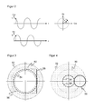
- FIG. 2 represents two purely exemplary, generated by a position sensor 20 sine and cosine signals.
- a certain, also purely by way of example arbitrarily selected position L can as right in the FIG. 2 shown with a pie chart.
- sine and cosine are plotted on the two axes, and a vector L of the two orthogonal sine and cosine components rotates with the phase or rotational position ⁇ .
- Such pie charts will be used hereafter to illustrate errors to be detected and procedures employed.
- the two sine and cosine signals can show a number of faulty images that are not recognized by a conventional vector length monitoring, as the signals are still in the allowable tolerance range even in the event of a fault. Such errors are dominated by the prior art via use as motor feedback. Although this is also possible according to the invention, as to FIG. 1b explains but not necessary. Rather, the errors shown below are revealed by the evaluation of the extreme values from the peak value holding device 32.
- FIG. 3 shows a pie chart for a first error image.
- the permissible values for the sine and cosine signals lie in a tolerance range shown hatched, which is determined by a mean nominal line 50, an outer boundary line 52 and an inner boundary line 54.
- the orbit erroneously suspected by a vector length method is shown with a dashed line 56, whereas the actual waveform is shown with a solid line 58.
- Numerical values are intentionally not plotted as usually all absolute values as well as tolerances that can still be tolerated are parameterized to the respective application. All the following error pictures in the FIGS. 4 to 8 are constructed according to this principle and accordingly provided with the same reference numerals.
- FIGS. 3 and 4 While in the error pictures according to FIGS. 3 and 4 the vector length even remains within the tolerance range at all times, they show FIGS. 5 to 8 various cases in which the tolerance range is left only temporarily. Again, this can usually go unnoticed if the sample rate is too small and subsampling causes the probed locations to be just within the tolerance range.
- FIG. 5 shows an error image in which one of the signals with too low an amplitude oscillates, but the resulting vector is still raised by the zero crossing of the low amplitude signal from the other signal in the tolerance range.
- FIG. 6 shows a case of an offset, in which, unlike in the case of FIG. 4 no longer the entire, but still a part of the actual circular path 58 is within the tolerance range.
- the FIGS. 7 and 8 are variants of it. In FIG. 7 the tolerance range is temporarily also left upwards, and in FIG. 8 remains the actual circular path 58 for the most part in the tolerance range, although the amplitude for objective viewing hardly or even insufficient.
- FIG. 9 11 shows a circular diagram illustrating the evaluation of the extreme values of the peak value device 32.
- the tolerance band is also shown hatched, while a solid line 58 shows the actual signal curve in the cycle or time interval in which the extreme values were detected.
- the peak hold device 32 is reset to begin a new evaluation cycle.
- the extreme values for the waveform 58 are in FIG. 9 indicated by dashed lines and on the axes.
- the error according to FIG. 3 is immediately recognized by the fact that a minimum and a maximum coincide, ie they do not differ by a minimum value. Likewise, none of the extreme values may lie outside the tolerance band, since this corresponds to an at least temporary error of which the FIGS. 5 to 8 Show examples.
- the stroke of the signals is monitored, ie the difference between maximum and minimum. If the sine signal shows a sufficient difference, a corresponding difference is also expected from the cosine signal. Conversely, with sufficient difference of the cosine signal, a corresponding difference of the sine signal is expected. This is in particular a "freezing" of a signal as in FIG. 3 or a shift as in FIG. 4 recognized. Preferably, the two tests are carried out in both directions.
- the "corresponding" expected difference of the other signal as a rule means no numerically identical difference, but the expectation is derived trigonometrically. That will be in FIG. 10 based on the error image according to FIG. 4 illustrated.
- the largest expected value is assumed to be the vector length 60. This is the maximum of the cosine. This vector has now only covered the angular range in the period under consideration, which is limited by the minimum and maximum of the sine. The largest possible difference in the cosine signal must therefore only be the length designated with expected value.
- This expectation value is calculated in a trigonometric view of the right-angled triangle, which is defined by the vector length as the hypotenuse and the minimum or maximum of the sinus as a catheter.
- the length of the other catheters and, as their difference to the vector length, the expected value can be calculated.
- the actual value of the fluctuation range of the cosine drawn in is larger than the expected value at which the error is detected.
- the expected difference is more closely monitored depending on the current vector length in terms of both overshoot and undershoot.
- the expected value can be for the two boundary values, ie as in FIG. 10 shown to be tested for the maximum of the sine and additionally for the minimum of the sine. As long as the cycle is not too large, which is preferred for reliable monitoring, the relevant cases are covered.
- FIG. 10 describes a test that defines expectation values via the sine signal, with which the cosine signal is then tested. As before, an alternate check with reversed roles of the two signals is alternatively or preferably additionally made here.
Landscapes
- Physics & Mathematics (AREA)
- General Physics & Mathematics (AREA)
- Transmission And Conversion Of Sensor Element Output (AREA)
Priority Applications (1)
| Application Number | Priority Date | Filing Date | Title |
|---|---|---|---|
| EP12197769.8A EP2746732B2 (fr) | 2012-12-18 | 2012-12-18 | Dispositif de transducteur et procédé destinés à la détermination d'une position |
Applications Claiming Priority (1)
| Application Number | Priority Date | Filing Date | Title |
|---|---|---|---|
| EP12197769.8A EP2746732B2 (fr) | 2012-12-18 | 2012-12-18 | Dispositif de transducteur et procédé destinés à la détermination d'une position |
Publications (3)
| Publication Number | Publication Date |
|---|---|
| EP2746732A1 true EP2746732A1 (fr) | 2014-06-25 |
| EP2746732B1 EP2746732B1 (fr) | 2015-02-25 |
| EP2746732B2 EP2746732B2 (fr) | 2018-03-07 |
Family
ID=47631188
Family Applications (1)
| Application Number | Title | Priority Date | Filing Date |
|---|---|---|---|
| EP12197769.8A Active EP2746732B2 (fr) | 2012-12-18 | 2012-12-18 | Dispositif de transducteur et procédé destinés à la détermination d'une position |
Country Status (1)
| Country | Link |
|---|---|
| EP (1) | EP2746732B2 (fr) |
Cited By (4)
| Publication number | Priority date | Publication date | Assignee | Title |
|---|---|---|---|---|
| EP3770559A1 (fr) | 2019-07-23 | 2021-01-27 | Sick Ag | Détermination de la position relative de deux objets mobiles l'un par rapport à l'autre |
| EP3828507A1 (fr) * | 2019-11-27 | 2021-06-02 | Sick Ag | Transducteur rotatif et dispositifs de surveillance d'un mouvement rotatif d'un transducteur rotatif |
| DE102020128726B3 (de) | 2020-11-02 | 2021-08-26 | Sick Ag | Gebervorrichtung und Verfahren zur Bestimmung einer Position |
| EP4345422A1 (fr) * | 2022-09-29 | 2024-04-03 | Rockwell Automation Technologies, Inc. | Système et procédé pour obtenir une intégrité de détection de position dans un système de chariot indépendant |
Citations (3)
| Publication number | Priority date | Publication date | Assignee | Title |
|---|---|---|---|---|
| DE10152427A1 (de) * | 2001-04-13 | 2002-10-24 | Mitsubishi Electric Corp | Vorrichtung und Verfahren zum Erfassen von Anomalie in einer Positionserfassungsvorrichtung |
| JP2006266727A (ja) * | 2005-03-22 | 2006-10-05 | Brother Ind Ltd | 光学式エンコーダの異常検出装置及び光学式エンコーダの異常検出方法 |
| US20090251134A1 (en) * | 2008-04-03 | 2009-10-08 | Denso Corporation | Rotation detection apparatus |
Family Cites Families (2)
| Publication number | Priority date | Publication date | Assignee | Title |
|---|---|---|---|---|
| US4318617A (en) † | 1979-12-14 | 1982-03-09 | Keuffel & Esser Company | DC Shift error correction for electro-optical measuring system |
| JP4079892B2 (ja) † | 2004-02-18 | 2008-04-23 | ファナック株式会社 | エンコーダ及び電動機の制御装置 |
-
2012
- 2012-12-18 EP EP12197769.8A patent/EP2746732B2/fr active Active
Patent Citations (3)
| Publication number | Priority date | Publication date | Assignee | Title |
|---|---|---|---|---|
| DE10152427A1 (de) * | 2001-04-13 | 2002-10-24 | Mitsubishi Electric Corp | Vorrichtung und Verfahren zum Erfassen von Anomalie in einer Positionserfassungsvorrichtung |
| JP2006266727A (ja) * | 2005-03-22 | 2006-10-05 | Brother Ind Ltd | 光学式エンコーダの異常検出装置及び光学式エンコーダの異常検出方法 |
| US20090251134A1 (en) * | 2008-04-03 | 2009-10-08 | Denso Corporation | Rotation detection apparatus |
Cited By (6)
| Publication number | Priority date | Publication date | Assignee | Title |
|---|---|---|---|---|
| EP3770559A1 (fr) | 2019-07-23 | 2021-01-27 | Sick Ag | Détermination de la position relative de deux objets mobiles l'un par rapport à l'autre |
| EP3828507A1 (fr) * | 2019-11-27 | 2021-06-02 | Sick Ag | Transducteur rotatif et dispositifs de surveillance d'un mouvement rotatif d'un transducteur rotatif |
| DE102020128726B3 (de) | 2020-11-02 | 2021-08-26 | Sick Ag | Gebervorrichtung und Verfahren zur Bestimmung einer Position |
| EP4345422A1 (fr) * | 2022-09-29 | 2024-04-03 | Rockwell Automation Technologies, Inc. | Système et procédé pour obtenir une intégrité de détection de position dans un système de chariot indépendant |
| US20240109735A1 (en) * | 2022-09-29 | 2024-04-04 | Rockwell Automation Technologies, Inc. | System and Method for Achieving Position Detection Integrity in an Independent Cart System |
| US12606387B2 (en) * | 2022-09-29 | 2026-04-21 | Rockwell Automation Technologies, Inc. | System and method for achieving position detection integrity in an independent cart system |
Also Published As
| Publication number | Publication date |
|---|---|
| EP2746732B2 (fr) | 2018-03-07 |
| EP2746732B1 (fr) | 2015-02-25 |
Similar Documents
| Publication | Publication Date | Title |
|---|---|---|
| EP2504900B1 (fr) | Circuit de sécurité et méthode pour une surveillance sûre d'un mouvement | |
| DE602005002763T2 (de) | Kodierer und Steuervorrichtung für Motor | |
| EP2746732B1 (fr) | Dispositif de transducteur et procédé destinés à la détermination d'une position | |
| DE102013224247A1 (de) | Multiturn-Drehgeber | |
| DE102011083042A1 (de) | Überwachungseinheit und Verfahren zur Überwachung von Positionssignalen inkrementaler Positionsmesseinrichtungen | |
| EP3321636B1 (fr) | Dispositif de mesure de position et son procédé de fonctionnement | |
| EP1593006B1 (fr) | Surveillance de securite sans redondance pour un dispositif d'entrainement electrique (avec capteur de mesure) | |
| DE102010051873B4 (de) | Integrierte Schaltungsanordnung und Verfahren zur Signalüberwachung | |
| EP3577422B1 (fr) | Procédé et dispositif pour surveiller les signaux de voie d'un capteur de changement de position | |
| DE102010024611B4 (de) | Sensoranordnung | |
| WO2010112131A1 (fr) | Surveillance d'un circuit microgénérateur d'un dispositif de détection tournant | |
| EP3382348B1 (fr) | Dispositif de mesure de position et procédé de fonctionnement d'un dispositif de mesure de position | |
| DE102018214601B4 (de) | System zum Erfassen der Position einer Lineareinheit eines Linearsystems | |
| WO2017194546A1 (fr) | Ensemble de surveillance destiné à surveiller un capteur de sécurité et procédé pour surveiller un capteur de sécurité | |
| EP1483621B1 (fr) | Procede et dispositif permettant de detecter l'angle d'ouverture d'un obturateur rotatif reglable dans une camera | |
| DE10360042A1 (de) | Verfahren und Meßsystem zur Bestimmung einer absoluten Winkellage | |
| EP2878929A1 (fr) | Encodeur à plusieurs rotations | |
| EP3473986B1 (fr) | Encodeur à plusieurs rotations et procédé de fonctionnement d'un encodeur à plusieurs rotations | |
| EP0342375B1 (fr) | Procédé pour contrôler les circuits rompus dans les lignes de raccordement de sondes linéaires à impulsion d'un capteur de rotation et circuit pour l'utilisation du procédé | |
| DE102020128726B3 (de) | Gebervorrichtung und Verfahren zur Bestimmung einer Position | |
| WO2006086944A1 (fr) | Procede et dispositif pour determiner la position d'un entrainement de reglage | |
| EP3770559A1 (fr) | Détermination de la position relative de deux objets mobiles l'un par rapport à l'autre | |
| DE102007020760B4 (de) | Messanordnung mit einem Datenkanal zur Datenübertragung eines Messsignals und eines Kontrollsignals | |
| DE102009009788B4 (de) | Vorrichtung und Verfahren zum berührungslosen Bestimmen einer Drehwinkelposition und/oder eines Stillstands eines drehbaren Objekts | |
| DE102020124933A1 (de) | Verfahren zum Überwachen einer Welle |
Legal Events
| Date | Code | Title | Description |
|---|---|---|---|
| PUAI | Public reference made under article 153(3) epc to a published international application that has entered the european phase |
Free format text: ORIGINAL CODE: 0009012 |
|
| 17P | Request for examination filed |
Effective date: 20130618 |
|
| AK | Designated contracting states |
Kind code of ref document: A1 Designated state(s): AL AT BE BG CH CY CZ DE DK EE ES FI FR GB GR HR HU IE IS IT LI LT LU LV MC MK MT NL NO PL PT RO RS SE SI SK SM TR |
|
| AX | Request for extension of the european patent |
Extension state: BA ME |
|
| GRAP | Despatch of communication of intention to grant a patent |
Free format text: ORIGINAL CODE: EPIDOSNIGR1 |
|
| INTG | Intention to grant announced |
Effective date: 20140730 |
|
| GRAS | Grant fee paid |
Free format text: ORIGINAL CODE: EPIDOSNIGR3 |
|
| GRAA | (expected) grant |
Free format text: ORIGINAL CODE: 0009210 |
|
| RBV | Designated contracting states (corrected) |
Designated state(s): AL AT BE BG CH CY CZ DE DK EE ES FI FR GB GR HR HU IE IS IT LI LT LU LV MC MK MT NL NO PL PT RO RS SE SI SK SM TR |
|
| AK | Designated contracting states |
Kind code of ref document: B1 Designated state(s): AL AT BE BG CH CY CZ DE DK EE ES FI FR GB GR HR HU IE IS IT LI LT LU LV MC MK MT NL NO PL PT RO RS SE SI SK SM TR |
|
| REG | Reference to a national code |
Ref country code: GB Ref legal event code: FG4D Free format text: NOT ENGLISH |
|
| REG | Reference to a national code |
Ref country code: CH Ref legal event code: EP |
|
| REG | Reference to a national code |
Ref country code: IE Ref legal event code: FG4D Free format text: LANGUAGE OF EP DOCUMENT: GERMAN |
|
| REG | Reference to a national code |
Ref country code: DE Ref legal event code: R096 Ref document number: 502012002356 Country of ref document: DE Effective date: 20150409 |
|
| REG | Reference to a national code |
Ref country code: AT Ref legal event code: REF Ref document number: 712365 Country of ref document: AT Kind code of ref document: T Effective date: 20150415 |
|
| REG | Reference to a national code |
Ref country code: NL Ref legal event code: VDEP Effective date: 20150225 |
|
| REG | Reference to a national code |
Ref country code: LT Ref legal event code: MG4D |
|
| PG25 | Lapsed in a contracting state [announced via postgrant information from national office to epo] |
Ref country code: FI Free format text: LAPSE BECAUSE OF FAILURE TO SUBMIT A TRANSLATION OF THE DESCRIPTION OR TO PAY THE FEE WITHIN THE PRESCRIBED TIME-LIMIT Effective date: 20150225 Ref country code: LT Free format text: LAPSE BECAUSE OF FAILURE TO SUBMIT A TRANSLATION OF THE DESCRIPTION OR TO PAY THE FEE WITHIN THE PRESCRIBED TIME-LIMIT Effective date: 20150225 Ref country code: ES Free format text: LAPSE BECAUSE OF FAILURE TO SUBMIT A TRANSLATION OF THE DESCRIPTION OR TO PAY THE FEE WITHIN THE PRESCRIBED TIME-LIMIT Effective date: 20150225 Ref country code: SE Free format text: LAPSE BECAUSE OF FAILURE TO SUBMIT A TRANSLATION OF THE DESCRIPTION OR TO PAY THE FEE WITHIN THE PRESCRIBED TIME-LIMIT Effective date: 20150225 Ref country code: NO Free format text: LAPSE BECAUSE OF FAILURE TO SUBMIT A TRANSLATION OF THE DESCRIPTION OR TO PAY THE FEE WITHIN THE PRESCRIBED TIME-LIMIT Effective date: 20150525 Ref country code: HR Free format text: LAPSE BECAUSE OF FAILURE TO SUBMIT A TRANSLATION OF THE DESCRIPTION OR TO PAY THE FEE WITHIN THE PRESCRIBED TIME-LIMIT Effective date: 20150225 |
|
| PG25 | Lapsed in a contracting state [announced via postgrant information from national office to epo] |
Ref country code: RS Free format text: LAPSE BECAUSE OF FAILURE TO SUBMIT A TRANSLATION OF THE DESCRIPTION OR TO PAY THE FEE WITHIN THE PRESCRIBED TIME-LIMIT Effective date: 20150225 Ref country code: IS Free format text: LAPSE BECAUSE OF FAILURE TO SUBMIT A TRANSLATION OF THE DESCRIPTION OR TO PAY THE FEE WITHIN THE PRESCRIBED TIME-LIMIT Effective date: 20150625 Ref country code: LV Free format text: LAPSE BECAUSE OF FAILURE TO SUBMIT A TRANSLATION OF THE DESCRIPTION OR TO PAY THE FEE WITHIN THE PRESCRIBED TIME-LIMIT Effective date: 20150225 Ref country code: GR Free format text: LAPSE BECAUSE OF FAILURE TO SUBMIT A TRANSLATION OF THE DESCRIPTION OR TO PAY THE FEE WITHIN THE PRESCRIBED TIME-LIMIT Effective date: 20150526 |
|
| PG25 | Lapsed in a contracting state [announced via postgrant information from national office to epo] |
Ref country code: NL Free format text: LAPSE BECAUSE OF FAILURE TO SUBMIT A TRANSLATION OF THE DESCRIPTION OR TO PAY THE FEE WITHIN THE PRESCRIBED TIME-LIMIT Effective date: 20150225 |
|
| PG25 | Lapsed in a contracting state [announced via postgrant information from national office to epo] |
Ref country code: DK Free format text: LAPSE BECAUSE OF FAILURE TO SUBMIT A TRANSLATION OF THE DESCRIPTION OR TO PAY THE FEE WITHIN THE PRESCRIBED TIME-LIMIT Effective date: 20150225 Ref country code: RO Free format text: LAPSE BECAUSE OF FAILURE TO SUBMIT A TRANSLATION OF THE DESCRIPTION OR TO PAY THE FEE WITHIN THE PRESCRIBED TIME-LIMIT Effective date: 20150225 Ref country code: SK Free format text: LAPSE BECAUSE OF FAILURE TO SUBMIT A TRANSLATION OF THE DESCRIPTION OR TO PAY THE FEE WITHIN THE PRESCRIBED TIME-LIMIT Effective date: 20150225 Ref country code: EE Free format text: LAPSE BECAUSE OF FAILURE TO SUBMIT A TRANSLATION OF THE DESCRIPTION OR TO PAY THE FEE WITHIN THE PRESCRIBED TIME-LIMIT Effective date: 20150225 Ref country code: CZ Free format text: LAPSE BECAUSE OF FAILURE TO SUBMIT A TRANSLATION OF THE DESCRIPTION OR TO PAY THE FEE WITHIN THE PRESCRIBED TIME-LIMIT Effective date: 20150225 |
|
| REG | Reference to a national code |
Ref country code: DE Ref legal event code: R026 Ref document number: 502012002356 Country of ref document: DE |
|
| PLBI | Opposition filed |
Free format text: ORIGINAL CODE: 0009260 |
|
| PG25 | Lapsed in a contracting state [announced via postgrant information from national office to epo] |
Ref country code: PL Free format text: LAPSE BECAUSE OF FAILURE TO SUBMIT A TRANSLATION OF THE DESCRIPTION OR TO PAY THE FEE WITHIN THE PRESCRIBED TIME-LIMIT Effective date: 20150225 |
|
| REG | Reference to a national code |
Ref country code: FR Ref legal event code: PLFP Year of fee payment: 4 |
|
| 26 | Opposition filed |
Opponent name: DR. JOHANNES HEIDENHAIN GMBH Effective date: 20151125 |
|
| PG25 | Lapsed in a contracting state [announced via postgrant information from national office to epo] |
Ref country code: IT Free format text: LAPSE BECAUSE OF FAILURE TO SUBMIT A TRANSLATION OF THE DESCRIPTION OR TO PAY THE FEE WITHIN THE PRESCRIBED TIME-LIMIT Effective date: 20150225 |
|
| PLAX | Notice of opposition and request to file observation + time limit sent |
Free format text: ORIGINAL CODE: EPIDOSNOBS2 |
|
| PLBB | Reply of patent proprietor to notice(s) of opposition received |
Free format text: ORIGINAL CODE: EPIDOSNOBS3 |
|
| PG25 | Lapsed in a contracting state [announced via postgrant information from national office to epo] |
Ref country code: SI Free format text: LAPSE BECAUSE OF FAILURE TO SUBMIT A TRANSLATION OF THE DESCRIPTION OR TO PAY THE FEE WITHIN THE PRESCRIBED TIME-LIMIT Effective date: 20150225 |
|
| PG25 | Lapsed in a contracting state [announced via postgrant information from national office to epo] |
Ref country code: BE Free format text: LAPSE BECAUSE OF NON-PAYMENT OF DUE FEES Effective date: 20151231 |
|
| PG25 | Lapsed in a contracting state [announced via postgrant information from national office to epo] |
Ref country code: LU Free format text: LAPSE BECAUSE OF FAILURE TO SUBMIT A TRANSLATION OF THE DESCRIPTION OR TO PAY THE FEE WITHIN THE PRESCRIBED TIME-LIMIT Effective date: 20151218 Ref country code: MC Free format text: LAPSE BECAUSE OF FAILURE TO SUBMIT A TRANSLATION OF THE DESCRIPTION OR TO PAY THE FEE WITHIN THE PRESCRIBED TIME-LIMIT Effective date: 20150225 |
|
| REG | Reference to a national code |
Ref country code: IE Ref legal event code: MM4A |
|
| PG25 | Lapsed in a contracting state [announced via postgrant information from national office to epo] |
Ref country code: IE Free format text: LAPSE BECAUSE OF NON-PAYMENT OF DUE FEES Effective date: 20151218 |
|
| REG | Reference to a national code |
Ref country code: FR Ref legal event code: PLFP Year of fee payment: 5 |
|
| PGFP | Annual fee paid to national office [announced via postgrant information from national office to epo] |
Ref country code: CH Payment date: 20161222 Year of fee payment: 5 |
|
| PG25 | Lapsed in a contracting state [announced via postgrant information from national office to epo] |
Ref country code: HU Free format text: LAPSE BECAUSE OF FAILURE TO SUBMIT A TRANSLATION OF THE DESCRIPTION OR TO PAY THE FEE WITHIN THE PRESCRIBED TIME-LIMIT; INVALID AB INITIO Effective date: 20121218 Ref country code: BG Free format text: LAPSE BECAUSE OF FAILURE TO SUBMIT A TRANSLATION OF THE DESCRIPTION OR TO PAY THE FEE WITHIN THE PRESCRIBED TIME-LIMIT Effective date: 20150225 Ref country code: SM Free format text: LAPSE BECAUSE OF FAILURE TO SUBMIT A TRANSLATION OF THE DESCRIPTION OR TO PAY THE FEE WITHIN THE PRESCRIBED TIME-LIMIT Effective date: 20150225 |
|
| RIC2 | Information provided on ipc code assigned after grant |
Ipc: G01D 5/244 20060101AFI20170523BHEP |
|
| PG25 | Lapsed in a contracting state [announced via postgrant information from national office to epo] |
Ref country code: CY Free format text: LAPSE BECAUSE OF FAILURE TO SUBMIT A TRANSLATION OF THE DESCRIPTION OR TO PAY THE FEE WITHIN THE PRESCRIBED TIME-LIMIT Effective date: 20150225 |
|
| PG25 | Lapsed in a contracting state [announced via postgrant information from national office to epo] |
Ref country code: MT Free format text: LAPSE BECAUSE OF FAILURE TO SUBMIT A TRANSLATION OF THE DESCRIPTION OR TO PAY THE FEE WITHIN THE PRESCRIBED TIME-LIMIT Effective date: 20150225 |
|
| REG | Reference to a national code |
Ref country code: FR Ref legal event code: PLFP Year of fee payment: 6 |
|
| PUAH | Patent maintained in amended form |
Free format text: ORIGINAL CODE: 0009272 |
|
| STAA | Information on the status of an ep patent application or granted ep patent |
Free format text: STATUS: PATENT MAINTAINED AS AMENDED |
|
| 27A | Patent maintained in amended form |
Effective date: 20180307 |
|
| AK | Designated contracting states |
Kind code of ref document: B2 Designated state(s): AL AT BE BG CH CY CZ DE DK EE ES FI FR GB GR HR HU IE IS IT LI LT LU LV MC MK MT NL NO PL PT RO RS SE SI SK SM TR |
|
| REG | Reference to a national code |
Ref country code: DE Ref legal event code: R102 Ref document number: 502012002356 Country of ref document: DE |
|
| REG | Reference to a national code |
Ref country code: CH Ref legal event code: AELC |
|
| PG25 | Lapsed in a contracting state [announced via postgrant information from national office to epo] |
Ref country code: MK Free format text: LAPSE BECAUSE OF FAILURE TO SUBMIT A TRANSLATION OF THE DESCRIPTION OR TO PAY THE FEE WITHIN THE PRESCRIBED TIME-LIMIT Effective date: 20150225 Ref country code: PT Free format text: LAPSE BECAUSE OF FAILURE TO SUBMIT A TRANSLATION OF THE DESCRIPTION OR TO PAY THE FEE WITHIN THE PRESCRIBED TIME-LIMIT Effective date: 20150225 |
|
| REG | Reference to a national code |
Ref country code: CH Ref legal event code: PL |
|
| PG25 | Lapsed in a contracting state [announced via postgrant information from national office to epo] |
Ref country code: TR Free format text: LAPSE BECAUSE OF FAILURE TO SUBMIT A TRANSLATION OF THE DESCRIPTION OR TO PAY THE FEE WITHIN THE PRESCRIBED TIME-LIMIT Effective date: 20150225 Ref country code: AL Free format text: LAPSE BECAUSE OF FAILURE TO SUBMIT A TRANSLATION OF THE DESCRIPTION OR TO PAY THE FEE WITHIN THE PRESCRIBED TIME-LIMIT Effective date: 20150225 |
|
| PG25 | Lapsed in a contracting state [announced via postgrant information from national office to epo] |
Ref country code: LI Free format text: LAPSE BECAUSE OF NON-PAYMENT OF DUE FEES Effective date: 20171231 Ref country code: CH Free format text: LAPSE BECAUSE OF NON-PAYMENT OF DUE FEES Effective date: 20171231 |
|
| REG | Reference to a national code |
Ref country code: AT Ref legal event code: MM01 Ref document number: 712365 Country of ref document: AT Kind code of ref document: T Effective date: 20171218 |
|
| PGFP | Annual fee paid to national office [announced via postgrant information from national office to epo] |
Ref country code: FR Payment date: 20181218 Year of fee payment: 7 Ref country code: GB Payment date: 20181219 Year of fee payment: 7 |
|
| PG25 | Lapsed in a contracting state [announced via postgrant information from national office to epo] |
Ref country code: AT Free format text: LAPSE BECAUSE OF NON-PAYMENT OF DUE FEES Effective date: 20171218 |
|
| GBPC | Gb: european patent ceased through non-payment of renewal fee |
Effective date: 20191218 |
|
| PG25 | Lapsed in a contracting state [announced via postgrant information from national office to epo] |
Ref country code: GB Free format text: LAPSE BECAUSE OF NON-PAYMENT OF DUE FEES Effective date: 20191218 Ref country code: FR Free format text: LAPSE BECAUSE OF NON-PAYMENT OF DUE FEES Effective date: 20191231 |
|
| PGFP | Annual fee paid to national office [announced via postgrant information from national office to epo] |
Ref country code: DE Payment date: 20251222 Year of fee payment: 14 |