EP2746743A1 - Élément de mesure de pression - Google Patents
Élément de mesure de pression Download PDFInfo
- Publication number
- EP2746743A1 EP2746743A1 EP12198676.4A EP12198676A EP2746743A1 EP 2746743 A1 EP2746743 A1 EP 2746743A1 EP 12198676 A EP12198676 A EP 12198676A EP 2746743 A1 EP2746743 A1 EP 2746743A1
- Authority
- EP
- European Patent Office
- Prior art keywords
- conductive element
- insulation
- pressure measurement
- layer
- measurement member
- Prior art date
- Legal status (The legal status is an assumption and is not a legal conclusion. Google has not performed a legal analysis and makes no representation as to the accuracy of the status listed.)
- Ceased
Links
Images







Classifications
-
- G—PHYSICS
- G01—MEASURING; TESTING
- G01L—MEASURING FORCE, STRESS, TORQUE, WORK, MECHANICAL POWER, MECHANICAL EFFICIENCY, OR FLUID PRESSURE
- G01L1/00—Measuring force or stress, in general
- G01L1/20—Measuring force or stress, in general by measuring variations in ohmic resistance of solid materials or of electrically-conductive fluids; by making use of electrokinetic cells, i.e. liquid-containing cells wherein an electrical potential is produced or varied upon the application of stress
-
- G—PHYSICS
- G01—MEASURING; TESTING
- G01L—MEASURING FORCE, STRESS, TORQUE, WORK, MECHANICAL POWER, MECHANICAL EFFICIENCY, OR FLUID PRESSURE
- G01L1/00—Measuring force or stress, in general
- G01L1/20—Measuring force or stress, in general by measuring variations in ohmic resistance of solid materials or of electrically-conductive fluids; by making use of electrokinetic cells, i.e. liquid-containing cells wherein an electrical potential is produced or varied upon the application of stress
- G01L1/205—Measuring force or stress, in general by measuring variations in ohmic resistance of solid materials or of electrically-conductive fluids; by making use of electrokinetic cells, i.e. liquid-containing cells wherein an electrical potential is produced or varied upon the application of stress using distributed sensing elements
-
- G—PHYSICS
- G01—MEASURING; TESTING
- G01L—MEASURING FORCE, STRESS, TORQUE, WORK, MECHANICAL POWER, MECHANICAL EFFICIENCY, OR FLUID PRESSURE
- G01L9/00—Measuring steady of quasi-steady pressure of fluid or fluent solid material by electric or magnetic pressure-sensitive elements; Transmitting or indicating the displacement of mechanical pressure-sensitive elements, used to measure the steady or quasi-steady pressure of a fluid or fluent solid material, by electric or magnetic means
- G01L9/0041—Transmitting or indicating the displacement of flexible diaphragms
- G01L9/0051—Transmitting or indicating the displacement of flexible diaphragms using variations in ohmic resistance
- G01L9/0057—Transmitting or indicating the displacement of flexible diaphragms using variations in ohmic resistance of potentiometers
Definitions
- the present invention relates to a measurement member and particularly to a pressure measurement member.
- Piezoresistive material now has been employed to improve pressure measurement capability and sensitivity.
- flexible electronic elements also have been developed.
- the flexible electronic elements mostly include plastic electronic element, printed electronic element, organic electronic element and polymer electronic element and the like.
- U.S. patent No. 7,980,144 entitled “FLEXIBLE ELECTRONICS FOR PRESSURE DEVICE AND FABRICATION METHOD THEREOF” discloses a pressure measurement structure for a flexible electronic element to prevent erroneous contact of elements located on different films. It also aims to reduce total cost of the structure. Flexible electronic material is prone to output unstable electric signals when subject to bending and could result in measurement errors. Hence there is accuracy concern on measurement results. To avoid the aforesaid problem material selection is very important. As selection of flexible electronic material applied to the pressure measurement elements is fewer, the material cost is higher.
- the primary object of the present invention is to overcome the problem of conventional pressure measurement elements that has fewer material selections and higher costs.
- the present invention provides a pressure measurement member connecting to at least one first electric transmission line and at least one second electric transmission line. It includes an insulation bottom layer, a flexible insulation top layer and at least one spacer.
- the insulation bottom layer has at lease one bottom conductive element on the surface connecting electrically to the first electric transmission line.
- the flexible insulation top layer is opposite to the insulation bottom layer and has at least one top conductive element on the surface thereof adjacent to the insulation bottom layer to connect electrically to the second electric transmission line.
- the top conductive element is opposite to the bottom conductive element.
- the spacer is located between the insulation bottom layer and flexible insulation top layer without contacting the bottom conductive element and top conductive element, thereby separates the insulation bottom layer and flexible insulation top layer.
- the impedance between the top conductive element and bottom conductive element is in inverse proportion to the contact area.
- the applied pressure can be derived.
- the pressure measurement member of the invention mentioned above can be an analog sensor to obtain pressure location and amount via impedance variation formed on the contact area.
- the invention further provides a digital pressure measurement member that includes an insulation bottom layer, a flexible insulation top layer and at least one spacer.
- the insulation bottom layer has a bottom conductive element on the surface thereof.
- the flexible insulation top layer is opposite to the insulation bottom layer and has a plurality of top conductive elements on the surface thereof adjacent to the insulation bottom layer.
- the top conductive elements are opposite to the bottom conductive element.
- the spacer is located between the insulation bottom layer and flexible insulation top layer to form separation between them.
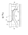
- FIGS. 1A and 1B Please refer to FIGS. 1A and 1B for a first embodiment of the pressure measurement member of the invention. It is an analog device in this embodiment and connected to a first electric transmission line 41 and a second electric transmission line 42, and includes an insulation bottom layer 10, a flexible insulation top layer 20 and at least one spacer 30.
- the insulation bottom layer 10 has a bottom conductive element 11 on the surface connecting electrically to the first electric transmission line 41.
- the flexible insulation top layer 20 is opposite to the insulation bottom layer 10 and has a top conductive element 21 on the surface thereof adjacent to the insulation bottom layer 10 to connect electrically to the second electric transmission line 42.
- the top conductive element 21 is opposite to the bottom conductive element 11.
- the spacer 30 is located between the insulation bottom layer 10 and flexible insulation top layer 20 without contacting the bottom conductive element 11 and top conductive element 21, thereby separates the insulation bottom layer 10 and flexible insulation top layer 20.
- Different pressures affect contact area of the top conductive element 21 and bottom conductive element 11.
- the impedance between the top conductive element 21 and bottom conductive element 11 is in inverse proportion to the contact area. Through the impedance variation, the applied pressure is derived.
- the flexibility of the flexible insulation top layer 20 is greater than that of the top conductive element 21, hence the material cost of the top conductive element 21 can be reduced.
- the top conductive element 21 can be made of conductive ink, conductive polymer, indium tin oxide (ITO), anisotropic conductive film (ACF) or combinations thereof.
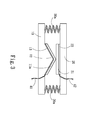
- the insulation bottom layer 10 has a protrusive portion 12 located on one side of the bottom conductive element 11a remote from the flexible insulation top layer 20.
- the bottom conductive element 11a is attached to the protrusive portion 12 to conform to the shape of the protrusive portion.
- the spacer 30a is made of elastic material.
- the protrusive portion 12 is formed in a triangle with a vertex facing the flexible insulation top layer 20. Referring to FIG. 2B , when a downward pressure is applied, the top conductive element 21 is first in contact with the bottom conductive element 11a at the vertex of the triangle with a smaller contact area, thus the measured impedance is higher; referring to FIG. 2C , when the applied pressure is greater, the top conductive element 21 is in contact with the bottom conductive element 11a with a greater area, thus the measured impedance is smaller and can serve as the judgment criterion of the pressure measurement member.
- the flexible insulation top layer 20 further has a high conductive element 22 located between the flexible insulation top layer 20 and top conductive element 21.
- the second electric transmission line 42 is electrically connected to the top conductive element 21 via the high conductive element 22.
- the top conductive element 21 has impedance greater than that of the high conductive element 22. More specifically, the impedance of the top conductive element 21 is more ten times than that of the high conductive element 22. As the top conductive element 21 has higher impedance, the contact area with the bottom conductive element 11 greatly impacts the impedance performance.
- the impedance of the top conductive element 21 when the impedance of the top conductive element 21 is greater, the greater the contact area it is formed with the bottom conductive element 11 the smaller the total impedance becomes. By contrast, when the contact area between the top conductive element 21 and bottom conductive element 11 is smaller total impedance is greater. If the top conductive element 21 is directly connected to the second electric transmission line 42, because of the greater impedance of the material at varying locations of the top conductive element 21 different voltage surfaces are formed. Through the high conductive element 22, the voltage of the first electric transmission line 41 can be evenly distributed thereon, and any position of the top conductive element 21 in contact with the high conductive element 22 may have the same voltage, thus can reduce errors caused by uneven voltage.
- the insulation bottom layer 10 and bottom conductive element 11a can also be interposed by a bottom high conductive element 13 which is electrically connected to the first electric transmission line 41. Thereby the error caused by uneven voltage during power transmission from the first electric transmission line 41 to the bottom conductive element 11a can be reduced.
- the high conductive element 22 can also be disposed between the bottom conductive element 11 and insulation bottom layer 10.
- two high conductive elements 22 are provided respectively between the bottom conductive element 11 and insulation bottom layer 10, and between the top conductive element 21 and flexible insulation top layer 20 so that any location on the surface of the bottom conductive element 11 and top conductive element 21 has the same voltage to avoid voltage drop caused by the impedance.
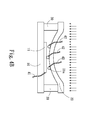
- FIGS. 4A through 4C for a fourth embodiment of the invention.
- It is a digital pressure measurement member. It includes an insulation bottom layer 10, a flexible insulation top layer 20 and at least one spacer 30.
- the insulation bottom layer 10 has a bottom conductive element 11 on the surface thereof.
- the flexible insulation top layer 20 is opposite to the insulation bottom layer 10 and has a plurality of top conductive elements 21a on the surface thereof adjacent to the insulation bottom layer 10 and opposite to the bottom conductive element 11.
- the spacers 30 are located between the insulation bottom layer 10 and flexible insulation top layer 20 for separation. Referring to FIG. 4B , when a downward pressure is applied, those top conductive elements 21a being moved deeper connect to the bottom conductive element 11 first and become conductive. With increasing of the pressure, referring to FIG. 4C , more top conductive elements 21a connect to the bottom conductive element 11 to become conductive. By detecting the number of the top conductive elements 21a that are conductive the size of pressurized area and amount of pressure can be derived.
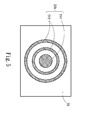
- the top conductive element 21b can also include a circular conductive sheet 211 and a plurality of annular conductive rings 212 arranged concentrically about the circular conductive sheet 211.
- the circular conductive sheet 211 is conducted first; when the downward pressure increases, the annular conductive rings 212 are also conducted, thereby the conductive pressure can be known.
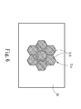
- the top conductive element 21c can include a plurality of hexagonal conductive sheets 213 with one located in the center and the rest surrounding the center to form a radial conductive structure. As it also is arranged concentrically, it is possible to measure the intensity of the downward pressure. It is to be noted that the top conductive elements 21b and 21c previously discussed are merely examples to facilitate discussion, in practice this design also can be utilized in the insulation bottom layer 10 but not limited to the flexible insulation top layer 20.
- the pressure measurement member is analog type or digital type
- multiple sets of the bottom conductive elements 11 and top conductive elements 21 are provided, and multiple insulation bottom layers 10 are also provided to correspond to the bottom conductive elements 11, and multiple spacers 30 are further provided at the surrounding to balance the pressure.
- the bottom conductive elements 11 and top conductive elements 21 are arranged correspondingly to each other to form a matrix structure to increase pressure measurement scope.
- the amount of pressure can be determined.
- the amount of pressure also can be derived from the number that the top conductive elements are in contact with the bottom conductive elements when the pressure is applied.
Landscapes
- Physics & Mathematics (AREA)
- General Physics & Mathematics (AREA)
- Force Measurement Appropriate To Specific Purposes (AREA)
- Measuring Fluid Pressure (AREA)
Priority Applications (1)
| Application Number | Priority Date | Filing Date | Title |
|---|---|---|---|
| EP12198676.4A EP2746743A1 (fr) | 2012-12-20 | 2012-12-20 | Élément de mesure de pression |
Applications Claiming Priority (1)
| Application Number | Priority Date | Filing Date | Title |
|---|---|---|---|
| EP12198676.4A EP2746743A1 (fr) | 2012-12-20 | 2012-12-20 | Élément de mesure de pression |
Publications (1)
| Publication Number | Publication Date |
|---|---|
| EP2746743A1 true EP2746743A1 (fr) | 2014-06-25 |
Family
ID=47605347
Family Applications (1)
| Application Number | Title | Priority Date | Filing Date |
|---|---|---|---|
| EP12198676.4A Ceased EP2746743A1 (fr) | 2012-12-20 | 2012-12-20 | Élément de mesure de pression |
Country Status (1)
| Country | Link |
|---|---|
| EP (1) | EP2746743A1 (fr) |
Cited By (2)
| Publication number | Priority date | Publication date | Assignee | Title |
|---|---|---|---|---|
| CN114323367A (zh) * | 2021-12-07 | 2022-04-12 | 华南理工大学 | 一种柔性桥式开关传感器 |
| EP4073482A1 (fr) * | 2019-12-13 | 2022-10-19 | Peratech Holdco Ltd | Dispositif capteur de pression |
Citations (8)
| Publication number | Priority date | Publication date | Assignee | Title |
|---|---|---|---|---|
| US4493219A (en) * | 1982-08-02 | 1985-01-15 | Illinois Tool Works, Inc. | Force transducer |
| US4503705A (en) * | 1982-02-24 | 1985-03-12 | The Langer Biomechanics Group, Inc. | Flexible force sensor |
| US20040000195A1 (en) * | 2002-06-27 | 2004-01-01 | Kenichi Yanai | Pressure sensor |
| EP1821088A1 (fr) * | 2006-02-16 | 2007-08-22 | IEE International Electronics & Engineering S.A.R.L. | Mât de détection de la pression |
| US7409876B2 (en) * | 2005-06-02 | 2008-08-12 | Fidelica Microsystems | Authentication system having a flexible imaging pressure sensor |
| WO2010101174A1 (fr) * | 2009-03-05 | 2010-09-10 | コニカミノルタホールディングス株式会社 | Dispositif capteur de pression |
| US20110084346A1 (en) * | 2009-03-06 | 2011-04-14 | Marusan Name Co., Ltd. | Pressure sensor and method of manufacturing the same |
| US7980144B2 (en) | 2008-10-15 | 2011-07-19 | Industrial Technology Research Institute | Flexible electronics for pressure device and fabrication method thereof |
-
2012
- 2012-12-20 EP EP12198676.4A patent/EP2746743A1/fr not_active Ceased
Patent Citations (8)
| Publication number | Priority date | Publication date | Assignee | Title |
|---|---|---|---|---|
| US4503705A (en) * | 1982-02-24 | 1985-03-12 | The Langer Biomechanics Group, Inc. | Flexible force sensor |
| US4493219A (en) * | 1982-08-02 | 1985-01-15 | Illinois Tool Works, Inc. | Force transducer |
| US20040000195A1 (en) * | 2002-06-27 | 2004-01-01 | Kenichi Yanai | Pressure sensor |
| US7409876B2 (en) * | 2005-06-02 | 2008-08-12 | Fidelica Microsystems | Authentication system having a flexible imaging pressure sensor |
| EP1821088A1 (fr) * | 2006-02-16 | 2007-08-22 | IEE International Electronics & Engineering S.A.R.L. | Mât de détection de la pression |
| US7980144B2 (en) | 2008-10-15 | 2011-07-19 | Industrial Technology Research Institute | Flexible electronics for pressure device and fabrication method thereof |
| WO2010101174A1 (fr) * | 2009-03-05 | 2010-09-10 | コニカミノルタホールディングス株式会社 | Dispositif capteur de pression |
| US20110084346A1 (en) * | 2009-03-06 | 2011-04-14 | Marusan Name Co., Ltd. | Pressure sensor and method of manufacturing the same |
Cited By (3)
| Publication number | Priority date | Publication date | Assignee | Title |
|---|---|---|---|---|
| EP4073482A1 (fr) * | 2019-12-13 | 2022-10-19 | Peratech Holdco Ltd | Dispositif capteur de pression |
| CN114323367A (zh) * | 2021-12-07 | 2022-04-12 | 华南理工大学 | 一种柔性桥式开关传感器 |
| CN114323367B (zh) * | 2021-12-07 | 2023-08-22 | 华南理工大学 | 一种柔性桥式开关传感器 |
Similar Documents
| Publication | Publication Date | Title |
|---|---|---|
| TWI617954B (zh) | 一種壓力感測輸入裝置 | |
| CN105793686B (zh) | 输入装置以及输入装置的控制方法 | |
| CN105955535B (zh) | 一种显示面板 | |
| JP5587491B1 (ja) | 電子機器及び電子機器の制御方法 | |
| CN104407466B (zh) | 一种显示基板、显示面板和显示装置 | |
| CN105929577B (zh) | 显示面板、显示装置及显示面板的制造方法 | |
| JP5567734B1 (ja) | 入力装置 | |
| US20100328258A1 (en) | Touch panel and detecting method thereof | |
| US8714020B2 (en) | Pressure measurement member | |
| TW201709038A (zh) | 一種三維觸控裝置 | |
| KR101312550B1 (ko) | 신축성 촉각센서를 구비한 유연 터치패널, 신축성 촉각센서 및 그 제조방법 | |
| EP3781909B1 (fr) | Capteur à haute résistance et son procédé d'utilisation | |
| CN204808289U (zh) | 触摸屏及显示装置 | |
| JP4882016B2 (ja) | タッチセンサ | |
| WO2015098254A1 (fr) | Dispositif d'entrée et procédé de production de dispositif d'entrée | |
| CN106293285A (zh) | 触摸屏及显示装置 | |
| CN107045216A (zh) | 一种具有压力检测功能的电子设备 | |
| CN103091005B (zh) | 压力感测构件 | |
| CN211425725U (zh) | 一种界面压力平衡校正系统 | |
| JP2014126373A (ja) | 圧力検出装置 | |
| US20230400368A1 (en) | Sensor | |
| CN107562245A (zh) | 触摸显示装置及电子设备 | |
| JP2006184098A (ja) | 感圧センサ | |
| CN108762566A (zh) | 触控显示模组及显示装置 | |
| LU102398B1 (en) | Sensor device |
Legal Events
| Date | Code | Title | Description |
|---|---|---|---|
| PUAI | Public reference made under article 153(3) epc to a published international application that has entered the european phase |
Free format text: ORIGINAL CODE: 0009012 |
|
| 17P | Request for examination filed |
Effective date: 20121220 |
|
| AK | Designated contracting states |
Kind code of ref document: A1 Designated state(s): AL AT BE BG CH CY CZ DE DK EE ES FI FR GB GR HR HU IE IS IT LI LT LU LV MC MK MT NL NO PL PT RO RS SE SI SK SM TR |
|
| AX | Request for extension of the european patent |
Extension state: BA ME |
|
| R17P | Request for examination filed (corrected) |
Effective date: 20140912 |
|
| RBV | Designated contracting states (corrected) |
Designated state(s): AL AT BE BG CH CY CZ DE DK EE ES FI FR GB GR HR HU IE IS IT LI LT LU LV MC MK MT NL NO PL PT RO RS SE SI SK SM TR |
|
| STAA | Information on the status of an ep patent application or granted ep patent |
Free format text: STATUS: EXAMINATION IS IN PROGRESS |
|
| 17Q | First examination report despatched |
Effective date: 20170504 |
|
| STAA | Information on the status of an ep patent application or granted ep patent |
Free format text: STATUS: THE APPLICATION HAS BEEN REFUSED |
|
| 18R | Application refused |
Effective date: 20191114 |