EP2746749A1 - Agencement de capteur optique et procédé de mesure d'un élément observable - Google Patents
Agencement de capteur optique et procédé de mesure d'un élément observable Download PDFInfo
- Publication number
- EP2746749A1 EP2746749A1 EP12198075.9A EP12198075A EP2746749A1 EP 2746749 A1 EP2746749 A1 EP 2746749A1 EP 12198075 A EP12198075 A EP 12198075A EP 2746749 A1 EP2746749 A1 EP 2746749A1
- Authority
- EP
- European Patent Office
- Prior art keywords
- optical
- light
- resonator
- sensor arrangement
- resonators
- Prior art date
- Legal status (The legal status is an assumption and is not a legal conclusion. Google has not performed a legal analysis and makes no representation as to the accuracy of the status listed.)
- Withdrawn
Links
Images


Classifications
-
- G—PHYSICS
- G01—MEASURING; TESTING
- G01N—INVESTIGATING OR ANALYSING MATERIALS BY DETERMINING THEIR CHEMICAL OR PHYSICAL PROPERTIES
- G01N21/00—Investigating or analysing materials by the use of optical means, i.e. using sub-millimetre waves, infrared, visible or ultraviolet light
- G01N21/75—Systems in which material is subjected to a chemical reaction, the progress or the result of the reaction being investigated
- G01N21/77—Systems in which material is subjected to a chemical reaction, the progress or the result of the reaction being investigated by observing the effect on a chemical indicator
- G01N21/7703—Systems in which material is subjected to a chemical reaction, the progress or the result of the reaction being investigated by observing the effect on a chemical indicator using reagent-clad optical fibres or optical waveguides
- G01N21/7746—Systems in which material is subjected to a chemical reaction, the progress or the result of the reaction being investigated by observing the effect on a chemical indicator using reagent-clad optical fibres or optical waveguides the waveguide coupled to a cavity resonator
Definitions
- the minute change translates into a small change of the optical length of the resonator.
- optical sensor arrangement including the features of claim 1.
- the problem can also be solved by a method for measuring at least two observables using an optical sensor arrangement as described herein. Further embodiments, developments, or alternatives to the invention may be accomplished by basing them on features of the dependent claims or the alternatives presented hereafter. Specifically, different embodiments of an optical sensor arrangement may leave out specific features from claim 1 or include alternatives to features found in claim 1.
- the first optical resonator has a first optical length which is variable depending on one of the at least two observables.
- the second optical resonator is variable depending on the other of the at least two observables.
- the first and second optical resonators of the second cascade circuit are coupled to the detector unit by a separate optical path.
- a separate optical path it is understood that, for example, different waveguides may be employed to transport light from the first or second optical resonators to the detector unit.
- the light of the separate waveguides may be bundled by a coupler and then coupled to a detector unit to simplify and reduce the number of waveguides.
- the first cascade circuit includes only a single FCOR31.
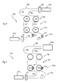
- Said optical resonator further includes a drop port 33 which is coupled to a waveguide 5, which is realized as a rib for guiding light.
- the rib leads to the second cascade circuit 6 which includes a first optical resonator 61 and a second optical resonator 62.
- Both optical resonators are microrings in this example but could be realized as Fabry-Perot or photonic crystal resonators.
- Each of the optical resonators 61 and 62 include an entry port 63 and 64, respectively, a drop port 65 and 66, respectively, as well as a layer of active material 67 and 68, respectively.
- switch 69 is on while switch 70 is off.
- a signal S can be detected at the output of the amplifier 92.
- the signal is forwarded to the control unit 10 and correlated with the state of the switches, and it is then clear that light responsible for signal S has passed the first optical resonator only.
- the second resonance peak at the wavelength of ⁇ 2 coincides with the second transmission peak of spectrum R2 in its active state.
- the third transmission peak of wavelength ⁇ 3 coincides with the third transmission of spectrum R1.
- Figures 4 and 5 disclose alternative embodiments using separate optical paths to couple light from the light generation circuit to the first and second optical resonators.
- a light generation circuit 402 is coupled to optical path circuit 404, which includes an optical coupler 441, a first optical path 442 including an optical switch 443, and a second optical path 444 including a second optical switch 445.
- the optical paths 442 and 444 couple individually to a first and a second optical resonator 431 and 432, respectively, of the first cascade circuit 403.
- Light exiting the first or second optical resonators of the second cascade circuit 406 is coupled to a detector unit 409 by optical path circuit 408 which includes optical path 481 and optical path 482.
- optical path circuit 408 which includes optical path 481 and optical path 482.
- the light of both these optical paths is coupled by optical coupler 483 and forwarded to the detector unit.
- switches as shown in Fig. 4 are located in different parts of the circuit, they fulfill the same function as the switches in the embodiment of Fig. 1 .
- the switches By switching on or off either switch 443 or switch 445, light only passes the first optical resonator 461 or the second optical resonator 462.
- the switches are merely used for making signal analysis easier since no other interference occurs between light passing the first optical resonator 461 and the second optical resonator 462.
- optical sensor arrangement 504 may not include modulators 533 and 534 since the spatial resolution of the camera of detector unit 509 is sufficient to separate the signals.
Landscapes
- Physics & Mathematics (AREA)
- Chemical & Material Sciences (AREA)
- Engineering & Computer Science (AREA)
- Chemical Kinetics & Catalysis (AREA)
- Plasma & Fusion (AREA)
- Health & Medical Sciences (AREA)
- Life Sciences & Earth Sciences (AREA)
- Analytical Chemistry (AREA)
- Biochemistry (AREA)
- General Health & Medical Sciences (AREA)
- General Physics & Mathematics (AREA)
- Immunology (AREA)
- Pathology (AREA)
- Optical Modulation, Optical Deflection, Nonlinear Optics, Optical Demodulation, Optical Logic Elements (AREA)
- Optical Integrated Circuits (AREA)
Priority Applications (2)
| Application Number | Priority Date | Filing Date | Title |
|---|---|---|---|
| EP12198075.9A EP2746749A1 (fr) | 2012-12-19 | 2012-12-19 | Agencement de capteur optique et procédé de mesure d'un élément observable |
| PCT/IB2013/060501 WO2014097028A1 (fr) | 2012-12-19 | 2013-11-29 | Agencement de capteur optique et capteur pour mesure d'observable |
Applications Claiming Priority (1)
| Application Number | Priority Date | Filing Date | Title |
|---|---|---|---|
| EP12198075.9A EP2746749A1 (fr) | 2012-12-19 | 2012-12-19 | Agencement de capteur optique et procédé de mesure d'un élément observable |
Publications (1)
| Publication Number | Publication Date |
|---|---|
| EP2746749A1 true EP2746749A1 (fr) | 2014-06-25 |
Family
ID=47563061
Family Applications (1)
| Application Number | Title | Priority Date | Filing Date |
|---|---|---|---|
| EP12198075.9A Withdrawn EP2746749A1 (fr) | 2012-12-19 | 2012-12-19 | Agencement de capteur optique et procédé de mesure d'un élément observable |
Country Status (2)
| Country | Link |
|---|---|
| EP (1) | EP2746749A1 (fr) |
| WO (1) | WO2014097028A1 (fr) |
Cited By (1)
| Publication number | Priority date | Publication date | Assignee | Title |
|---|---|---|---|---|
| CN119846773A (zh) * | 2025-01-09 | 2025-04-18 | 国网(西安)环保技术中心有限公司 | 一种光子集成芯片、土壤界面动态监测装置及方法 |
Families Citing this family (1)
| Publication number | Priority date | Publication date | Assignee | Title |
|---|---|---|---|---|
| CN114543873B (zh) * | 2022-01-11 | 2023-08-04 | 中国地质大学(武汉) | 一种基于游标效应的片上折射率与温度双参量传感器 |
Citations (2)
| Publication number | Priority date | Publication date | Assignee | Title |
|---|---|---|---|---|
| EP1207513A1 (fr) | 2000-11-17 | 2002-05-22 | SANYO ELECTRIC Co., Ltd. | Dispositiv d'affichage à cristaux liquides du type à matrice active avec pixels comprenants des mémoires analogiques et numériques |
| WO2011000494A1 (fr) | 2009-07-01 | 2011-01-06 | Fraunhofer-Gesellschaft zur Förderung der angewandten Forschung e.V. | Détecteur optique et procédé de détection de molécules |
Family Cites Families (4)
| Publication number | Priority date | Publication date | Assignee | Title |
|---|---|---|---|---|
| US6643421B1 (en) * | 1999-09-21 | 2003-11-04 | Lnl Technologies, Inc. | Wavelength-slicing architecture for wavelength demultiplexing using micro-ring resonators |
| US7065276B2 (en) * | 2003-04-03 | 2006-06-20 | Lambda Crossing Ltd. | Integrated optical filters utilizing resonators |
| US7796262B1 (en) * | 2007-05-31 | 2010-09-14 | Nomadics, Inc. | Integrated optical resonator device for measuring chemical and biological analyte concentrations |
| WO2011091735A1 (fr) * | 2010-01-29 | 2011-08-04 | 浙江大学 | Capteur optique a base de source de lumiere large bande et filtre de guide d'onde optique en cascade |
-
2012
- 2012-12-19 EP EP12198075.9A patent/EP2746749A1/fr not_active Withdrawn
-
2013
- 2013-11-29 WO PCT/IB2013/060501 patent/WO2014097028A1/fr not_active Ceased
Patent Citations (2)
| Publication number | Priority date | Publication date | Assignee | Title |
|---|---|---|---|---|
| EP1207513A1 (fr) | 2000-11-17 | 2002-05-22 | SANYO ELECTRIC Co., Ltd. | Dispositiv d'affichage à cristaux liquides du type à matrice active avec pixels comprenants des mémoires analogiques et numériques |
| WO2011000494A1 (fr) | 2009-07-01 | 2011-01-06 | Fraunhofer-Gesellschaft zur Förderung der angewandten Forschung e.V. | Détecteur optique et procédé de détection de molécules |
Non-Patent Citations (4)
| Title |
|---|
| CHARIS MESARITAKIS ET AL: "Adaptive Interrogation for Fast Optical Sensing Based on Cascaded Micro-Ring Resonators", IEEE SENSORS JOURNAL, IEEE SERVICE CENTER, NEW YORK, NY, US, vol. 11, no. 7, 1 July 2011 (2011-07-01), pages 1595 - 1601, XP011323405, ISSN: 1530-437X, DOI: 10.1109/JSEN.2010.2086057 * |
| PERGANDE DANIEL ET AL: "Integrated optical sensor array for biochemical multiparameter analysis", FRONTIERS IN BIOLOGICAL DETECTION: FROM NANOSENSORS TO SYSTEMS IV, SPIE, 1000 20TH ST. BELLINGHAM WA 98225-6705 USA, vol. 8212, no. 1, 30 January 2012 (2012-01-30), pages 1 - 7, XP060023167, DOI: 10.1117/12.906375 * |
| TOM CLAES ET AL: "Experimental characterization of a silicon photonic biosensor consisting of two cascaded ring resonators based on the Vernier-effect and introduction of a curve fitting method for an improved detection limit References and linksBasic structures for photonic integrated circuits in silicon", ANAL. CHIM. ACTA ANAL. BIOANAL. CHEM. OPT. EXPRESS OPT. EXPRESS OPT. LETT. J. MICROMECH. MICROENG. OPT. EXPRESS IEEE PHOTON. TECHNOL. LETT. IEEE PHOTON. TECHNOL. LETT. OPT. EXPRESS IEEE PHOTON. TECHNOL. LETT. IEEE J. LIGHTWAVE TECHNOL. OPT. EXPRESS J, 1 January 2008 (2008-01-01), pages 8 - 26, XP055668914, Retrieved from the Internet <URL:https://biblio.ugent.be/publication/1154817/file/1154910.pdf> * |
| TOM CLAES ET AL: "Vernier-cascade label-free biosensor with integrated arrayed waveguide grating for wavelength interrogation with low-cost broadband source", OPTICS LETTERS, OSA, OPTICAL SOCIETY OF AMERICA, WASHINGTON, DC, US, vol. 36, no. 17, 1 September 2011 (2011-09-01), pages 3320 - 3322, XP001569459, ISSN: 0146-9592, [retrieved on 20110819], DOI: 10.1364/OL.36.003320 * |
Cited By (1)
| Publication number | Priority date | Publication date | Assignee | Title |
|---|---|---|---|---|
| CN119846773A (zh) * | 2025-01-09 | 2025-04-18 | 国网(西安)环保技术中心有限公司 | 一种光子集成芯片、土壤界面动态监测装置及方法 |
Also Published As
| Publication number | Publication date |
|---|---|
| WO2014097028A1 (fr) | 2014-06-26 |
Similar Documents
| Publication | Publication Date | Title |
|---|---|---|
| US9846060B2 (en) | Optical sensor arrangement and method for measuring an observable | |
| EP2699891B1 (fr) | Procédé de détection de molécules et capteur optique | |
| US9080953B2 (en) | Optical resonator for sensor arrangement and measuring method | |
| US8823947B2 (en) | Optical sensor and method for detecting molecules | |
| KR102356454B1 (ko) | 이중 커플러 소자, 상기 이중 커플러를 포함하는 분광기, 및 상기 분광기를 포함하는 비침습형 생체 센서 | |
| JP6180657B2 (ja) | スペクトル検知のためのチューナブルフィルタ | |
| US20110290002A1 (en) | Photoacoustic gas sensor and its use | |
| CN114502923B (zh) | 使用可调谐的光学带通滤波器询问光纤布拉格光栅型光纤传感器的方法和系统 | |
| JP7480031B2 (ja) | フォトニック回路における光学温度測定 | |
| US20210396581A1 (en) | Device and method for the spectroscopic analysis of brillouin scattered light | |
| US20130259747A1 (en) | Optical Biosensor | |
| EP2267432A1 (fr) | Système de capteur optique | |
| EP2746749A1 (fr) | Agencement de capteur optique et procédé de mesure d'un élément observable | |
| US9581545B2 (en) | Optical sensing system and method of determining a change in a refractive index in an optical sensing system | |
| US8379217B2 (en) | System and method for optical sensor interrogation | |
| EP2738547A1 (fr) | Agencement de capteur optique et procédé de mesure d'un élément observable | |
| EP2735862B1 (fr) | Agencement de capteur optique et procédé de mesure d'un élément observable | |
| JP5026988B2 (ja) | 近赤外線材料濃度測定とガラスファイバのファイバブラッググレーティングによる温度プロファイル測定との機械的結合 | |
| US6298185B1 (en) | Distributed fiber grating sensing systems using birefringence fiber interferometers for detecting wavelength shifts |
Legal Events
| Date | Code | Title | Description |
|---|---|---|---|
| PUAI | Public reference made under article 153(3) epc to a published international application that has entered the european phase |
Free format text: ORIGINAL CODE: 0009012 |
|
| 17P | Request for examination filed |
Effective date: 20121219 |
|
| AK | Designated contracting states |
Kind code of ref document: A1 Designated state(s): AL AT BE BG CH CY CZ DE DK EE ES FI FR GB GR HR HU IE IS IT LI LT LU LV MC MK MT NL NO PL PT RO RS SE SI SK SM TR |
|
| AX | Request for extension of the european patent |
Extension state: BA ME |
|
| R17P | Request for examination filed (corrected) |
Effective date: 20141104 |
|
| RBV | Designated contracting states (corrected) |
Designated state(s): AL AT BE BG CH CY CZ DE DK EE ES FI FR GB GR HR HU IE IS IT LI LT LU LV MC MK MT NL NO PL PT RO RS SE SI SK SM TR |
|
| 17Q | First examination report despatched |
Effective date: 20200228 |
|
| STAA | Information on the status of an ep patent application or granted ep patent |
Free format text: STATUS: THE APPLICATION HAS BEEN WITHDRAWN |
|
| 18W | Application withdrawn |
Effective date: 20200619 |