EP2746887B1 - Leistungsverbesserung für steilen Flugzeugansatz - Google Patents
Leistungsverbesserung für steilen Flugzeugansatz Download PDFInfo
- Publication number
- EP2746887B1 EP2746887B1 EP13197402.4A EP13197402A EP2746887B1 EP 2746887 B1 EP2746887 B1 EP 2746887B1 EP 13197402 A EP13197402 A EP 13197402A EP 2746887 B1 EP2746887 B1 EP 2746887B1
- Authority
- EP
- European Patent Office
- Prior art keywords
- aircraft
- mass
- trajectory
- drag
- processor
- Prior art date
- Legal status (The legal status is an assumption and is not a legal conclusion. Google has not performed a legal analysis and makes no representation as to the accuracy of the status listed.)
- Active
Links
Images



Classifications
-
- G—PHYSICS
- G05—CONTROLLING; REGULATING
- G05D—SYSTEMS FOR CONTROLLING OR REGULATING NON-ELECTRIC VARIABLES
- G05D1/00—Control of position, course, altitude or attitude of land, water, air or space vehicles, e.g. using automatic pilots
- G05D1/04—Control of altitude or depth
- G05D1/06—Rate of change of altitude or depth
- G05D1/0607—Rate of change of altitude or depth specially adapted for aircraft
- G05D1/0653—Rate of change of altitude or depth specially adapted for aircraft during a phase of take-off or landing
- G05D1/0676—Rate of change of altitude or depth specially adapted for aircraft during a phase of take-off or landing specially adapted for landing
-
- G—PHYSICS
- G08—SIGNALLING
- G08G—TRAFFIC CONTROL SYSTEMS
- G08G5/00—Traffic control systems for aircraft
- G08G5/50—Navigation or guidance aids
- G08G5/54—Navigation or guidance aids for approach or landing
Definitions
- the technology herein relates to control systems for aircraft, and more particularly to aircraft flight control and aircraft control law and associated automatic systems and methods. More particularly, the example non-limiting technology herein provides a flight control system which can achieve a relatively steep descent (using drag devices such as flight spoilers) at relatively low speeds while retaining good airplane handling qualities from the pilot's point of view.
- GB 2 444 742 A discloses an aircraft flight descend control system which commands drag devices or control surfaces according to pilot or autopilot command signals.
- the system monitors a set of flight parameters to determine whether the aircraft is operating inside a permitted safe envelope.
- the drag device is deployed such that the safe envelope is maintained during descend.
- US 2007/0057114 A1 describes a procedure and device for improving the maneuverability of an aircraft during the approach to landing, the aircraft being equipped with airbrakes.
- the airbrakes are put in a first deployed position during the approach phase, and as a function of a representative parameter of a given altitude and in case of a steep angle approach, they are actuated to transition to second more retracted position than the first position so as to achieve a flare-out allowing to essentially maintain the same angle of incidence.
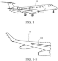
- Spoilers are plates on the top surface of a wing that can be extended upward into the airflow to "spoil” it. See Figure 1-1 .
- the spoiler creates a carefully controlled stall over the portion of the wing around it, greatly reducing the lift of that wing section. As the wing's lift decreases, the aircraft will assume a trajectory angle characteristic of the approach phase up to landing.
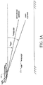
- Figure 1A contrasts example non-limiting conventional and steep approach procedures for an aircraft 10.
- Typical conventional approaches use a trajectory angle of around -3.3 degrees.
- the trajectory angle for a steep approach is much larger-for example, on the order of -5.5 degrees (mathematically, 0° > ⁇ appr > ⁇ steep appr.).
- Some operations require capability to perform a steady flight in a steeper descent path.
- a given airplane may lack this capability, especially in low airspeed conditions (e.g., those airspeed values commonly used to approach and landing).
- the most commonly used solution is to introduce devices, mechanisms and methods to produce even more drag on the airplane utilizing the flight spoilers and/or other drag devices such as airbrakes, dive brakes and others, in order to allow a steeper descent trajectory.
- the spoiler is biased to a predetermined position and a control feedback circuit is used to command the spoiler around the predetermined bias position.
- This predetermined bias position permits the aircraft to perform a steep approach landing in a predetermined flight envelope which includes different weight configurations.
- This bias position is typically dimensioned to cover the range of aircraft weight inside the steep approach flight envelope.
- spoiler bias position normally requires an increase in the approach airspeed in order to preserve or maintain sufficient margin above stall.
- the example non-limiting technology herein adds a function that sets the biased position of the drag device(s) (spoilers, for example) depending on factors such as:
- the example non-limiting technology herein is capable of modulating the control position of drag devices as a function of pilot longitudinal commands in order to enhance glide slope control during approach, flare and landing. Also alternatively or additionally, the example non-limiting technology herein is capable of modulating the control position of drag devices as a function of only one of the three factors mentioned above (the airplane estimated weight, measured flight path angle or pilot longitudinal command) or as a function of any combination among these three factors (which may be a combination between two or among three of them).
- the example non-limiting technology herein is capable of defining a function of drag device deployment as a function of only one of the three factors among the aircraft mass, trajectory angle and pilot inceptor position and/or movement or as a function of any combination among these three factors which may be a combination between two or among three of them.
- the example non-limiting technology herein also provides for automatically retracting of the drag devices, if the angle of attack reaches a predefined threshold, in order to keep unchanged stall speeds and maneuvering capability.
- the example non-limiting technology herein enables a steep approach and landing with a higher airplane weight.
- One benefit allows operation with a higher payload (e.g., more passengers). This means that fewer airplanes are needed to carry a given payload, which in a final analysis, can reduce air traffic and consequently fuel emissions.
- an example non-limiting system and method may optimize the drag device positioning used to perform the Steep Approach to improve its performance.
- One example non-limiting embodiment provides means (e.g., probes) of measuring air data, means (e.g., AHRS) of measuring aircraft inertial information, means (e.g., inceptor) of sensing pilot input, means (e.g., Fly-By-Wire or avionics system) to process data and computing outputs to command the drag devices, means (e.g., hydraulic or electromechanical actuators) of actuating the drag devices and finally the drag devices itself (e.g., spoilers).
- means e.g., probes
- means e.g., AHRS
- inceptor e.g., inceptor of sensing pilot input
- means e.g., Fly-By-Wire or avionics system
- means e.g., hydraulic or electromechanical actuators of actuating the drag devices and finally the drag devices itself (e.g.
- information obtained from the air data and the inertial system is fed back to estimate the current aircraft mass.
- This estimation is properly filtered to avoid high frequency content not pertinent to the aircraft's mass dynamics.
- the Steep Approach Logic receives the estimated aircraft mass together with the current aircraft trajectory angle and the desired trajectory angle (supplied by the pilot) to compute the optimum drag device position (drag device command) which is carried out by the drag device actuators.
- the drag devices are gradually repositioned to a position which provides suitable drag to perform steep approach.
- the drag devices are also repositioned based on current trajectory angle and the trajectory angle desired by the pilot. For example, when the pilot intends to perform a steeper glide slope, after keeping the aircraft in the desired trajectory angle for a certain amount (period) of time, the drag devices are automatically repositioned to a position which provides suitable drag to perform steep approach with the desired trajectory angle.
- the drag devices when performing a steep approach, if the pilot intends to perform a conventional approach (e.g., glide slope around 3 degrees), the drag devices will be automatically repositioned to provide suitable drag after a certain amount of time to reduce the drag.
- the repositioning of the drag devices due to variations in the estimated mass, the current trajectory angle and the desired angle is, in one example non-limiting implementation, completely transparent to the pilot.
- the non-limiting system may adjust itself without any additional commands by the crew.
- the example non-limiting technology herein eliminates the need for an increased approach airspeed and consequently improves the aircraft maximum landing weight.
- the Figure 2 example non-limiting system and method may optimize the drag device positioning used to perform the Steep Approach to improve its performance.
- means 104 of sensing pilot input is connected to a pilot input device such as an inceptor 102.
- a means (e.g., probes) 108 of measuring air data and a means (e.g., AHRS) 110 of measuring aircraft inertial information supply additional inputs to a means (e.g., Fly-By-Wire or avionics system) 106 to process data and computing outputs to command the drag devices 114.
- a means e.g., Fly-By-Wire or avionics system
- the means 106 can comprise a general purpose CPU coupled to a non-transitory memory means 107 storing program instructions that are executed by the processor, or could comprise other implementations such as programmed logic and/or a digital signal processor. These alternatives are all referred to herein as "processor.”
- the means 106 provides control outputs to means (e.g., hydraulic or electromechanical actuators) 112 of actuating the drag devices. Means 112 is coupled to drag devices 114 such as spoilers.
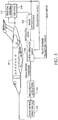
- Figure 3 shows a different schematic illustration of the means 106 to process data and computing outputs to command the drag devices 114.
- the inertial navigation system 152 and air data sensor system 154 on board the aircraft 10 provide inputs to a mass estimator 156 that estimates the mass of the aircraft.
- the inertial navigation system 152 can determine current trajectory of the aircraft 10 based on for example a 3-axis gyroscope and/or other sensors.
- the steep approach logic 158 also receives pilot desired trajectory angle from a pilot input device such as inceptor 102. Based on these inputs, steep approach logic 158 develops a draft device command that it applies to drag device actuators 160 (see means 112 above) to accomplish drag device positioning 162.
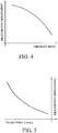
- Figure 4 shows an example control function performed by steep approach logic 158 to control drag device employment as a function of aircraft mass.
- Figure 4 shows that as aircraft mass decreases, the amount of drag required from drag devices such as spoilers increases to have the same effect on aircraft trajectory.
- Figure 5 shows an example control function based on trajectory angle. This Figure shows that as trajectory angle (which is negative and thus ranges from 0 to -x degrees) increases, drag device deployment must increase based on a non-linear function. Thus, a steeper approach trajectory will require much more drag from the spoilers.
- Figure 6 depicts example non-limiting drag device deployment as a function of aircraft mass and inceptor input for a normal steep approach glide slope.
- This Figure 6 shows curves A1, A2, A3 (a family of curves) which correspond, for the purpose of illustrating a non-limiting implementation, to three values of aircraft mass (Mass 1, Mass 2, Mass 3). If the aircraft mass is initially at "Mass 3" and decreases during flight (e.g., based on fuel consumption), the necessary deployment of the drag devices increases. As the aircraft mass changes from Mass 3 to Mass 2 (where Mass 3 > Mass 2), the drag device deployment smoothly transitions from the curve A3 (corresponding to Mass 3) to curve A2 (corresponding to Mass 2).
- the drag devices are modulated according to a given value of aircraft mass, the current angle of the trajectory and the pilot longitudinal inceptor input.
Landscapes
- Engineering & Computer Science (AREA)
- Aviation & Aerospace Engineering (AREA)
- Physics & Mathematics (AREA)
- General Physics & Mathematics (AREA)
- Radar, Positioning & Navigation (AREA)
- Remote Sensing (AREA)
- Automation & Control Theory (AREA)
- Traffic Control Systems (AREA)
- Control Of Position, Course, Altitude, Or Attitude Of Moving Bodies (AREA)
Claims (10)
- Automatisches Steuersystem (100), das ein Mittel zum Empfangen und Verarbeiten von erfasster Luftinformation, die mindestens eine Luftgeschwindigkeit repräsentiert, und einer Steuereingabe, die eine Pilotensteuerorganposition (102) und/oder -bewegung repräsentiert, aufweist, wobei das System mindestens einen Prozessor (106) umfasst, der an eine nichttransitorische Speichervorrichtung, auf der Anweisungen gespeichert sind, gekoppelt ist, wobei der mindestens eine Prozessor (106) zum Ausführen der gespeicherten Anweisungen zum Steuern von mindestens einer Strömungswiderstandssteuerfläche (112), um eine Steilanflugtrajektorie eines Luftfahrzeugs bereitzustellen, eingerichtet ist, wobei das automatische Steuersystem dadurch gekennzeichnet ist, dass es ferner Mittel zum Empfangen und Verarbeiten von erfassten Inertialinformation (110), die mindestens eine Luftfahrzeugtrajektorie, repräsentiert, umfasst und der mindestens eine Prozessor (106) ferner eingereicht ist zu:Definieren einer Funktion einer Strömungswiderstandsvorrichtungs(114)-Verwendung als eine Funktion von nur einem der drei Faktoren der Luftfahrzeugmasse, des Trajektorienwinkels und der Pilotensteuerorgan(102)-Position und/oder -Bewegung oder als eine Funktion einer Kombination dieser drei Faktoren, bei der es sich um eine Kombination aus zwei oder drei von diesen handeln kann; undBereitstellen eines glatten Übergangs zwischen verschiedenen Kurven einer Familie von Kurven, wenn sich die Luftfahrzeugmasse, der Trajektorienwinkel und die Pilotensteuerorganposition und/oder -bewegung ändert.
- System nach Anspruch 1, wobei der Prozessor (106) ferner eingereicht ist, darauf basierend, dass die Trajektorie für mindestens eine vorbestimmte Zeitperiode einen vorbestimmten Schwellwert überschreitet, eine erste vorbestimmte Kurve, und darauf basierend, dass die Trajektorie für mindestens eine vorbestimmte Zeitperiode einen vorbestimmten Schwellwert nicht überschreitet, eine zweite vorbestimmte Kurve zu aktivieren.
- System nach Anspruch 1 oder Anspruch 2, das ferner einen Massenschätzer (156) aufweist, der auf Basis der Inertialinformation (152) und der Luftgeschwindigkeit (154) eine Luftfahrzeugmasse schätzt.
- System nach einem der vorhergehenden Ansprüche, das ferner einen Strömungswiderstandsvorrichtungsaktuator (160) aufweist.
- System nach einem der vorhergehenden Ansprüche, das ferner mindestens einen Inertialsensor (110) aufweist, der die Trajektorie des Luftfahrzeugs erfasst.
- System nach einem der vorhergehenden Ansprüche, das ferner einen Luftgeschwindigkeitssensor (108) aufweist.
- System nach einem der Ansprüche 1 bis 6, das ferner umfasst
Mittel zum Messen von Luftdaten (108);
Mittel zum Messen von Luftfahrzeuginertialinformationen (110);
Mittel zum Erfassen einer Piloteneingabe (104);
Mittel zum Verarbeiten von Daten und Berechnen von Ausgaben zum Kommandieren der Strömungswiderstandsvorrichtung, die an die Mittel zum Messen der Luftdaten, die Mittel zum Messen der Luftfahrzeuginertialinformation und die Mittel zum Erfassen der Piloteneingabe gekoppelt sind, und
Mittel zum Betätigen der mindestens einen Strömungswiderstandssteuerfläche (112), die an das Verarbeitungsmittel gekoppelt sind,
wobei die Mittel zum Verarbeiten von Daten und Berechnen von Ausgaben (106) den mindestens einen Prozessor aufweisen. - Automatisches Steuerverfahren zum Steuern von mindestens einer Strömungswiderstandsvorrichtung, um eine Steilanflugtrajektorie bereitzustellen, wobei das Verfahren Folgendes umfasst:Messen von Luftdaten;Erfassen einer Piloteneingabe;unter Verwendung mindestens eines Prozessors Verarbeiten von Daten und Berechnen von Ausgaben, um die mindestens eine Strömungswiderstandsvorrichtung zu steuern; undBetätigen der mindestens einen Strömungswiderstandsvorrichtung,wobei das automatische Steuerverfahren dadurch gekennzeichnet ist, dass es ferner den Schritt des Messens von Luftfahrzeuginertialinformation umfasst, undSchätzen einer Luftfahrzeugmasse auf Basis der Inertialinformation und der Luftdaten und Verwenden einer geschätzten Luftfahrzeugmasse, um die mindestens eine Strömungswiderstandsvorrichtung zu steuern.
- Verfahren nach Anspruch 8, wobei der Prozessor darauf basierend, dass die Trajektorie für mindestens eine vorbestimmte Zeitperiode einen vorbestimmten Schwellwert überschreitet, eine erste vorbestimmte Kurve, und darauf basierend, dass die Trajektorie für mindestens eine vorbestimmte Zeitperiode einen vorbestimmten Schwellwert nicht überschreitet, eine zweite vorbestimmte Kurve aktiviert.
- Verfahren nach einem der Ansprüche 8 bis 9, wobei der Prozessor
eine Funktion einer Strömungswiderstandsvorrichtungs-Verwendung als eine Funktion von nur einem von drei Faktoren von Luftfahrzeugmasse, Trajektorienwinkel und Pilotensteuerorganposition und/oder -bewegung oder als eine Funktion einer Kombination dieser drei Faktoren, bei der es sich um eine Kombination aus zwei oder drei von diesen handeln kann, definiert; und
einen glatten Übergang zwischen verschiedenen Kurven einer Familie von Kurven bereitstellt, wenn sich die Luftfahrzeugmasse, der Trajektorienwinkel und die Pilotensteuerorganposition und/oder -bewegung ändert.
Applications Claiming Priority (1)
| Application Number | Priority Date | Filing Date | Title |
|---|---|---|---|
| US201261745068P | 2012-12-21 | 2012-12-21 |
Publications (2)
| Publication Number | Publication Date |
|---|---|
| EP2746887A1 EP2746887A1 (de) | 2014-06-25 |
| EP2746887B1 true EP2746887B1 (de) | 2019-08-28 |
Family
ID=49918387
Family Applications (1)
| Application Number | Title | Priority Date | Filing Date |
|---|---|---|---|
| EP13197402.4A Active EP2746887B1 (de) | 2012-12-21 | 2013-12-16 | Leistungsverbesserung für steilen Flugzeugansatz |
Country Status (4)
| Country | Link |
|---|---|
| US (1) | US9153139B2 (de) |
| EP (1) | EP2746887B1 (de) |
| CN (1) | CN103885453B (de) |
| BR (1) | BR102013033134B1 (de) |
Families Citing this family (6)
| Publication number | Priority date | Publication date | Assignee | Title |
|---|---|---|---|---|
| US9734726B2 (en) * | 2014-02-17 | 2017-08-15 | The Boeing Company | Systems and methods for providing landing exceedance warnings and avoidance |
| US9845146B2 (en) * | 2015-10-23 | 2017-12-19 | The Boeing Company | Zoom climb prevention system for enhanced performance |
| CN106855418A (zh) * | 2015-12-08 | 2017-06-16 | 中国航空工业第六八研究所 | 一种抑制惯性航迹修正角噪声的方法 |
| EP3510586B1 (de) * | 2016-09-09 | 2025-07-16 | Bombardier Inc. | Automatische aktivierung einer steilanflugsfunktion eines flugzeugs |
| CN110546457B (zh) | 2017-05-02 | 2022-05-03 | 空客加拿大管理Gp公司 | 飞行器竖直速度的温度校正 |
| US10847044B2 (en) | 2018-02-28 | 2020-11-24 | Honeywell International Inc. | Systems and methods for presenting graphical display elements for variable or adaptive aircraft glideslope and safe areas for aircraft operations |
Family Cites Families (15)
| Publication number | Priority date | Publication date | Assignee | Title |
|---|---|---|---|---|
| US3589648A (en) | 1969-01-02 | 1971-06-29 | Lockheed Aircraft Corp | Means for controlling the vertical path of an aircraft |
| US3738594A (en) | 1971-08-16 | 1973-06-12 | Mc Donnell Douglas Corp | Lift control mechanism |
| US3774869A (en) | 1972-03-07 | 1973-11-27 | K Harmon | Combined throttle spoiler actuator for aircraft |
| US3850388A (en) | 1972-03-23 | 1974-11-26 | Nasa | Integrated lift/drag controller for aircraft |
| US4489907A (en) | 1982-06-23 | 1984-12-25 | Precise Flight, Inc. | Selectively integrated throttle spoiler actuator for aircraft |
| ITMI20012170A1 (it) * | 2001-10-18 | 2003-04-18 | Aermacchi S P A | Configurazione velivolo a prestazioni aerodinamiche migliorate |
| EP1768899B1 (de) | 2004-07-16 | 2013-12-11 | Airbus Operations | Verfahren und vorrichtung zur verbesserung der manövrierfähigkeit eines flugzeugs während der anflugphase vor der landung gefolgt von dem abfangen |
| FR2887065B1 (fr) * | 2005-06-14 | 2007-07-20 | Airbus France Sas | Procede et systeme d'aide au pilotage d'un aeronef volant a basse altitude |
| FR2891802B1 (fr) * | 2005-10-11 | 2009-03-13 | Airbus France Sas | Procede et dispositif pour attenuer sur un aeronef les effets d'une turbulence verticale |
| FR2900126B1 (fr) * | 2006-04-21 | 2008-12-26 | Airbus France Sas | Procede et dispositif pour la reduction des tourbillons de sillage d'un aeronef en phase d'approche/atterrissage |
| GB2444742B (en) * | 2006-12-11 | 2011-06-08 | Embraer Aeronautica Sa | Flight Control System |
| GB0810645D0 (en) * | 2008-06-11 | 2008-07-16 | Airbus Uk Ltd | Method of designing an airfoil assembly |
| US8798887B2 (en) * | 2011-11-30 | 2014-08-05 | GM Global Technology Operations LLC | System and method for estimating the mass of a vehicle |
| DE102012001268A1 (de) * | 2012-01-23 | 2013-07-25 | Airbus Operations Gmbh | Verfahren zur Planung eines Landeanflugs eines Flugzeugs, Computerprogrammprodukt, Medium mit einem darauf gespeicherten Landeanflugplan sowie Vorrichtung zur Planung eines Landeanflugs |
| US8788122B1 (en) * | 2012-08-24 | 2014-07-22 | The Boeing Company | Wing load alleviation methods and apparatus |
-
2013
- 2013-12-04 US US14/096,777 patent/US9153139B2/en active Active
- 2013-12-16 EP EP13197402.4A patent/EP2746887B1/de active Active
- 2013-12-20 BR BR102013033134-1A patent/BR102013033134B1/pt active IP Right Grant
- 2013-12-20 CN CN201310757168.2A patent/CN103885453B/zh active Active
Non-Patent Citations (1)
| Title |
|---|
| None * |
Also Published As
| Publication number | Publication date |
|---|---|
| EP2746887A1 (de) | 2014-06-25 |
| BR102013033134A2 (pt) | 2015-11-17 |
| CN103885453B (zh) | 2018-11-02 |
| US9153139B2 (en) | 2015-10-06 |
| CN103885453A (zh) | 2014-06-25 |
| US20140249704A1 (en) | 2014-09-04 |
| BR102013033134B1 (pt) | 2021-11-16 |
Similar Documents
| Publication | Publication Date | Title |
|---|---|---|
| US10647412B2 (en) | Flight control augmentation system and method for high aspect ratio aircraft including: motorglider aircraft, optionally piloted vehicles (OPVs) and unpiloted air vehicles (UAVs) | |
| EP3136197B1 (de) | Flugzeugströmungsabrissschutzsystem | |
| EP2787408B1 (de) | Endanflugsteuerung | |
| EP2224306B1 (de) | Automatischer Pilotenspitzenwinkelausgleich | |
| US9153139B2 (en) | Steep approach performance improvements and optimization | |
| US8442701B2 (en) | Dynamic roll angle stall protection for an aircraft | |
| CA2972495C (en) | Drift direction intended for a non-functional engine state | |
| US20090266940A1 (en) | Precision adjust split detent for a vehicle | |
| EP2998819B1 (de) | Verstellbare maximal steuerbare rollengeschwindigkeit für die richtungssteuerung eines flugzeugs während eines rollmanövers mit motorpanne | |
| EP3848289B1 (de) | Steuerungsgeräte und flugzeug mit system zum schutz vor strömungsabriss beim start | |
| CA2914291C (en) | A method of automatically controlling the descent phase of an aircraft using aircraft avionics executing a descent algorithm | |
| JP2016164060A5 (de) | ||
| CN106610585A (zh) | 用于增强性能的陡直爬升保护系统 | |
| US10671090B2 (en) | Automatic command for lift control devices |
Legal Events
| Date | Code | Title | Description |
|---|---|---|---|
| PUAI | Public reference made under article 153(3) epc to a published international application that has entered the european phase |
Free format text: ORIGINAL CODE: 0009012 |
|
| 17P | Request for examination filed |
Effective date: 20131216 |
|
| AK | Designated contracting states |
Kind code of ref document: A1 Designated state(s): AL AT BE BG CH CY CZ DE DK EE ES FI FR GB GR HR HU IE IS IT LI LT LU LV MC MK MT NL NO PL PT RO RS SE SI SK SM TR |
|
| AX | Request for extension of the european patent |
Extension state: BA ME |
|
| R17P | Request for examination filed (corrected) |
Effective date: 20141223 |
|
| RBV | Designated contracting states (corrected) |
Designated state(s): AL AT BE BG CH CY CZ DE DK EE ES FI FR GB GR HR HU IE IS IT LI LT LU LV MC MK MT NL NO PL PT RO RS SE SI SK SM TR |
|
| STAA | Information on the status of an ep patent application or granted ep patent |
Free format text: STATUS: EXAMINATION IS IN PROGRESS |
|
| 17Q | First examination report despatched |
Effective date: 20170911 |
|
| GRAP | Despatch of communication of intention to grant a patent |
Free format text: ORIGINAL CODE: EPIDOSNIGR1 |
|
| RIC1 | Information provided on ipc code assigned before grant |
Ipc: G05D 1/06 20060101AFI20190213BHEP Ipc: G08G 5/02 20060101ALI20190213BHEP |
|
| STAA | Information on the status of an ep patent application or granted ep patent |
Free format text: STATUS: GRANT OF PATENT IS INTENDED |
|
| INTG | Intention to grant announced |
Effective date: 20190321 |
|
| RAP1 | Party data changed (applicant data changed or rights of an application transferred) |
Owner name: EMBRAER S.A. |
|
| GRAS | Grant fee paid |
Free format text: ORIGINAL CODE: EPIDOSNIGR3 |
|
| GRAA | (expected) grant |
Free format text: ORIGINAL CODE: 0009210 |
|
| STAA | Information on the status of an ep patent application or granted ep patent |
Free format text: STATUS: THE PATENT HAS BEEN GRANTED |
|
| AK | Designated contracting states |
Kind code of ref document: B1 Designated state(s): AL AT BE BG CH CY CZ DE DK EE ES FI FR GB GR HR HU IE IS IT LI LT LU LV MC MK MT NL NO PL PT RO RS SE SI SK SM TR |
|
| REG | Reference to a national code |
Ref country code: GB Ref legal event code: FG4D |
|
| REG | Reference to a national code |
Ref country code: CH Ref legal event code: EP |
|
| REG | Reference to a national code |
Ref country code: AT Ref legal event code: REF Ref document number: 1173179 Country of ref document: AT Kind code of ref document: T Effective date: 20190915 |
|
| REG | Reference to a national code |
Ref country code: IE Ref legal event code: FG4D |
|
| REG | Reference to a national code |
Ref country code: DE Ref legal event code: R096 Ref document number: 602013059678 Country of ref document: DE |
|
| REG | Reference to a national code |
Ref country code: NL Ref legal event code: MP Effective date: 20190828 |
|
| REG | Reference to a national code |
Ref country code: LT Ref legal event code: MG4D |
|
| PG25 | Lapsed in a contracting state [announced via postgrant information from national office to epo] |
Ref country code: SE Free format text: LAPSE BECAUSE OF FAILURE TO SUBMIT A TRANSLATION OF THE DESCRIPTION OR TO PAY THE FEE WITHIN THE PRESCRIBED TIME-LIMIT Effective date: 20190828 Ref country code: NL Free format text: LAPSE BECAUSE OF FAILURE TO SUBMIT A TRANSLATION OF THE DESCRIPTION OR TO PAY THE FEE WITHIN THE PRESCRIBED TIME-LIMIT Effective date: 20190828 Ref country code: BG Free format text: LAPSE BECAUSE OF FAILURE TO SUBMIT A TRANSLATION OF THE DESCRIPTION OR TO PAY THE FEE WITHIN THE PRESCRIBED TIME-LIMIT Effective date: 20191128 Ref country code: NO Free format text: LAPSE BECAUSE OF FAILURE TO SUBMIT A TRANSLATION OF THE DESCRIPTION OR TO PAY THE FEE WITHIN THE PRESCRIBED TIME-LIMIT Effective date: 20191128 Ref country code: HR Free format text: LAPSE BECAUSE OF FAILURE TO SUBMIT A TRANSLATION OF THE DESCRIPTION OR TO PAY THE FEE WITHIN THE PRESCRIBED TIME-LIMIT Effective date: 20190828 Ref country code: PT Free format text: LAPSE BECAUSE OF FAILURE TO SUBMIT A TRANSLATION OF THE DESCRIPTION OR TO PAY THE FEE WITHIN THE PRESCRIBED TIME-LIMIT Effective date: 20191230 Ref country code: FI Free format text: LAPSE BECAUSE OF FAILURE TO SUBMIT A TRANSLATION OF THE DESCRIPTION OR TO PAY THE FEE WITHIN THE PRESCRIBED TIME-LIMIT Effective date: 20190828 Ref country code: LT Free format text: LAPSE BECAUSE OF FAILURE TO SUBMIT A TRANSLATION OF THE DESCRIPTION OR TO PAY THE FEE WITHIN THE PRESCRIBED TIME-LIMIT Effective date: 20190828 |
|
| PG25 | Lapsed in a contracting state [announced via postgrant information from national office to epo] |
Ref country code: LV Free format text: LAPSE BECAUSE OF FAILURE TO SUBMIT A TRANSLATION OF THE DESCRIPTION OR TO PAY THE FEE WITHIN THE PRESCRIBED TIME-LIMIT Effective date: 20190828 Ref country code: ES Free format text: LAPSE BECAUSE OF FAILURE TO SUBMIT A TRANSLATION OF THE DESCRIPTION OR TO PAY THE FEE WITHIN THE PRESCRIBED TIME-LIMIT Effective date: 20190828 Ref country code: IS Free format text: LAPSE BECAUSE OF FAILURE TO SUBMIT A TRANSLATION OF THE DESCRIPTION OR TO PAY THE FEE WITHIN THE PRESCRIBED TIME-LIMIT Effective date: 20191228 Ref country code: RS Free format text: LAPSE BECAUSE OF FAILURE TO SUBMIT A TRANSLATION OF THE DESCRIPTION OR TO PAY THE FEE WITHIN THE PRESCRIBED TIME-LIMIT Effective date: 20190828 Ref country code: GR Free format text: LAPSE BECAUSE OF FAILURE TO SUBMIT A TRANSLATION OF THE DESCRIPTION OR TO PAY THE FEE WITHIN THE PRESCRIBED TIME-LIMIT Effective date: 20191129 Ref country code: AL Free format text: LAPSE BECAUSE OF FAILURE TO SUBMIT A TRANSLATION OF THE DESCRIPTION OR TO PAY THE FEE WITHIN THE PRESCRIBED TIME-LIMIT Effective date: 20190828 |
|
| REG | Reference to a national code |
Ref country code: AT Ref legal event code: MK05 Ref document number: 1173179 Country of ref document: AT Kind code of ref document: T Effective date: 20190828 |
|
| PG25 | Lapsed in a contracting state [announced via postgrant information from national office to epo] |
Ref country code: TR Free format text: LAPSE BECAUSE OF FAILURE TO SUBMIT A TRANSLATION OF THE DESCRIPTION OR TO PAY THE FEE WITHIN THE PRESCRIBED TIME-LIMIT Effective date: 20190828 |
|
| PG25 | Lapsed in a contracting state [announced via postgrant information from national office to epo] |
Ref country code: PL Free format text: LAPSE BECAUSE OF FAILURE TO SUBMIT A TRANSLATION OF THE DESCRIPTION OR TO PAY THE FEE WITHIN THE PRESCRIBED TIME-LIMIT Effective date: 20190828 Ref country code: RO Free format text: LAPSE BECAUSE OF FAILURE TO SUBMIT A TRANSLATION OF THE DESCRIPTION OR TO PAY THE FEE WITHIN THE PRESCRIBED TIME-LIMIT Effective date: 20190828 Ref country code: DK Free format text: LAPSE BECAUSE OF FAILURE TO SUBMIT A TRANSLATION OF THE DESCRIPTION OR TO PAY THE FEE WITHIN THE PRESCRIBED TIME-LIMIT Effective date: 20190828 Ref country code: IT Free format text: LAPSE BECAUSE OF FAILURE TO SUBMIT A TRANSLATION OF THE DESCRIPTION OR TO PAY THE FEE WITHIN THE PRESCRIBED TIME-LIMIT Effective date: 20190828 Ref country code: EE Free format text: LAPSE BECAUSE OF FAILURE TO SUBMIT A TRANSLATION OF THE DESCRIPTION OR TO PAY THE FEE WITHIN THE PRESCRIBED TIME-LIMIT Effective date: 20190828 Ref country code: AT Free format text: LAPSE BECAUSE OF FAILURE TO SUBMIT A TRANSLATION OF THE DESCRIPTION OR TO PAY THE FEE WITHIN THE PRESCRIBED TIME-LIMIT Effective date: 20190828 |
|
| PG25 | Lapsed in a contracting state [announced via postgrant information from national office to epo] |
Ref country code: IS Free format text: LAPSE BECAUSE OF FAILURE TO SUBMIT A TRANSLATION OF THE DESCRIPTION OR TO PAY THE FEE WITHIN THE PRESCRIBED TIME-LIMIT Effective date: 20200224 Ref country code: SM Free format text: LAPSE BECAUSE OF FAILURE TO SUBMIT A TRANSLATION OF THE DESCRIPTION OR TO PAY THE FEE WITHIN THE PRESCRIBED TIME-LIMIT Effective date: 20190828 Ref country code: CZ Free format text: LAPSE BECAUSE OF FAILURE TO SUBMIT A TRANSLATION OF THE DESCRIPTION OR TO PAY THE FEE WITHIN THE PRESCRIBED TIME-LIMIT Effective date: 20190828 Ref country code: SK Free format text: LAPSE BECAUSE OF FAILURE TO SUBMIT A TRANSLATION OF THE DESCRIPTION OR TO PAY THE FEE WITHIN THE PRESCRIBED TIME-LIMIT Effective date: 20190828 |
|
| REG | Reference to a national code |
Ref country code: DE Ref legal event code: R097 Ref document number: 602013059678 Country of ref document: DE |
|
| REG | Reference to a national code |
Ref country code: DE Ref legal event code: R119 Ref document number: 602013059678 Country of ref document: DE |
|
| PLBE | No opposition filed within time limit |
Free format text: ORIGINAL CODE: 0009261 |
|
| STAA | Information on the status of an ep patent application or granted ep patent |
Free format text: STATUS: NO OPPOSITION FILED WITHIN TIME LIMIT |
|
| PG2D | Information on lapse in contracting state deleted |
Ref country code: IS |
|
| REG | Reference to a national code |
Ref country code: CH Ref legal event code: PL |
|
| 26N | No opposition filed |
Effective date: 20200603 |
|
| REG | Reference to a national code |
Ref country code: BE Ref legal event code: MM Effective date: 20191231 |
|
| PG25 | Lapsed in a contracting state [announced via postgrant information from national office to epo] |
Ref country code: MC Free format text: LAPSE BECAUSE OF FAILURE TO SUBMIT A TRANSLATION OF THE DESCRIPTION OR TO PAY THE FEE WITHIN THE PRESCRIBED TIME-LIMIT Effective date: 20190828 Ref country code: SI Free format text: LAPSE BECAUSE OF FAILURE TO SUBMIT A TRANSLATION OF THE DESCRIPTION OR TO PAY THE FEE WITHIN THE PRESCRIBED TIME-LIMIT Effective date: 20190828 |
|
| PG25 | Lapsed in a contracting state [announced via postgrant information from national office to epo] |
Ref country code: FR Free format text: LAPSE BECAUSE OF NON-PAYMENT OF DUE FEES Effective date: 20191231 Ref country code: IE Free format text: LAPSE BECAUSE OF NON-PAYMENT OF DUE FEES Effective date: 20191216 Ref country code: DE Free format text: LAPSE BECAUSE OF NON-PAYMENT OF DUE FEES Effective date: 20200701 Ref country code: LU Free format text: LAPSE BECAUSE OF NON-PAYMENT OF DUE FEES Effective date: 20191216 |
|
| PG25 | Lapsed in a contracting state [announced via postgrant information from national office to epo] |
Ref country code: LI Free format text: LAPSE BECAUSE OF NON-PAYMENT OF DUE FEES Effective date: 20191231 Ref country code: CH Free format text: LAPSE BECAUSE OF NON-PAYMENT OF DUE FEES Effective date: 20191231 Ref country code: BE Free format text: LAPSE BECAUSE OF NON-PAYMENT OF DUE FEES Effective date: 20191231 |
|
| PG25 | Lapsed in a contracting state [announced via postgrant information from national office to epo] |
Ref country code: CY Free format text: LAPSE BECAUSE OF FAILURE TO SUBMIT A TRANSLATION OF THE DESCRIPTION OR TO PAY THE FEE WITHIN THE PRESCRIBED TIME-LIMIT Effective date: 20190828 |
|
| PG25 | Lapsed in a contracting state [announced via postgrant information from national office to epo] |
Ref country code: HU Free format text: LAPSE BECAUSE OF FAILURE TO SUBMIT A TRANSLATION OF THE DESCRIPTION OR TO PAY THE FEE WITHIN THE PRESCRIBED TIME-LIMIT; INVALID AB INITIO Effective date: 20131216 Ref country code: MT Free format text: LAPSE BECAUSE OF FAILURE TO SUBMIT A TRANSLATION OF THE DESCRIPTION OR TO PAY THE FEE WITHIN THE PRESCRIBED TIME-LIMIT Effective date: 20190828 |
|
| PG25 | Lapsed in a contracting state [announced via postgrant information from national office to epo] |
Ref country code: MK Free format text: LAPSE BECAUSE OF FAILURE TO SUBMIT A TRANSLATION OF THE DESCRIPTION OR TO PAY THE FEE WITHIN THE PRESCRIBED TIME-LIMIT Effective date: 20190828 |
|
| PGFP | Annual fee paid to national office [announced via postgrant information from national office to epo] |
Ref country code: GB Payment date: 20251223 Year of fee payment: 13 |