EP2747103B1 - Kontaktschalter-Schutzschalter-Vorrichtung - Google Patents
Kontaktschalter-Schutzschalter-Vorrichtung Download PDFInfo
- Publication number
- EP2747103B1 EP2747103B1 EP13197642.5A EP13197642A EP2747103B1 EP 2747103 B1 EP2747103 B1 EP 2747103B1 EP 13197642 A EP13197642 A EP 13197642A EP 2747103 B1 EP2747103 B1 EP 2747103B1
- Authority
- EP
- European Patent Office
- Prior art keywords
- contacts
- contact
- switch
- support member
- axis
- Prior art date
- Legal status (The legal status is an assumption and is not a legal conclusion. Google has not performed a legal analysis and makes no representation as to the accuracy of the status listed.)
- Active
Links
- 239000004065 semiconductor Substances 0.000 claims description 20
- 238000010891 electric arc Methods 0.000 claims description 7
- 230000000295 complement effect Effects 0.000 claims description 2
- 239000004020 conductor Substances 0.000 claims description 2
- 238000004873 anchoring Methods 0.000 description 3
- 230000007423 decrease Effects 0.000 description 3
- 229910044991 metal oxide Inorganic materials 0.000 description 2
- 150000004706 metal oxides Chemical class 0.000 description 2
- 238000000926 separation method Methods 0.000 description 2
- 230000001419 dependent effect Effects 0.000 description 1
- 230000000694 effects Effects 0.000 description 1
- 230000003628 erosive effect Effects 0.000 description 1
- 230000005669 field effect Effects 0.000 description 1
- 238000002955 isolation Methods 0.000 description 1
- 238000004519 manufacturing process Methods 0.000 description 1
- 239000002184 metal Substances 0.000 description 1
- 210000000056 organ Anatomy 0.000 description 1
Images


Classifications
-
- H—ELECTRICITY
- H01—ELECTRIC ELEMENTS
- H01H—ELECTRIC SWITCHES; RELAYS; SELECTORS; EMERGENCY PROTECTIVE DEVICES
- H01H9/00—Details of switching devices, not covered by groups H01H1/00 - H01H7/00
- H01H9/30—Means for extinguishing or preventing arc between current-carrying parts
-
- H—ELECTRICITY
- H01—ELECTRIC ELEMENTS
- H01H—ELECTRIC SWITCHES; RELAYS; SELECTORS; EMERGENCY PROTECTIVE DEVICES
- H01H1/00—Contacts
- H01H1/12—Contacts characterised by the manner in which co-operating contacts engage
- H01H1/14—Contacts characterised by the manner in which co-operating contacts engage by abutting
- H01H1/20—Bridging contacts
-
- H—ELECTRICITY
- H01—ELECTRIC ELEMENTS
- H01H—ELECTRIC SWITCHES; RELAYS; SELECTORS; EMERGENCY PROTECTIVE DEVICES
- H01H1/00—Contacts
- H01H1/12—Contacts characterised by the manner in which co-operating contacts engage
- H01H1/14—Contacts characterised by the manner in which co-operating contacts engage by abutting
- H01H1/20—Bridging contacts
- H01H1/2016—Bridging contacts in which the two contact pairs commutate at substantially different moments
-
- H—ELECTRICITY
- H01—ELECTRIC ELEMENTS
- H01H—ELECTRIC SWITCHES; RELAYS; SELECTORS; EMERGENCY PROTECTIVE DEVICES
- H01H9/00—Details of switching devices, not covered by groups H01H1/00 - H01H7/00
- H01H9/54—Circuit arrangements not adapted to a particular application of the switching device and for which no provision exists elsewhere
- H01H9/541—Contacts shunted by semiconductor devices
- H01H9/542—Contacts shunted by static switch means
-
- H—ELECTRICITY
- H01—ELECTRIC ELEMENTS
- H01H—ELECTRIC SWITCHES; RELAYS; SELECTORS; EMERGENCY PROTECTIVE DEVICES
- H01H9/00—Details of switching devices, not covered by groups H01H1/00 - H01H7/00
- H01H9/54—Circuit arrangements not adapted to a particular application of the switching device and for which no provision exists elsewhere
- H01H9/547—Combinations of mechanical switches and static switches, the latter being controlled by the former
Definitions
- the present invention is in the field of contactor-circuit breaker devices.
- a contactor-circuit breaker device is an electrical appliance used for, on the one hand, voluntarily controlling the power supply of an electric circuit, that is to say exerting a contactor function, and on the other hand on the other hand, to automatically control the breaking of the current in the electrical circuit, that is to say to exert a circuit breaker function, by means of a breaking module, as soon as the breaking module detects an electrical fault such that a short circuit or overcurrent in the electrical circuit.
- a contactor-breaker device is said to be “hybrid” when it comprises both a mechanical switch and one or more semiconductor devices.
- the document WO 2011/018113 discloses a hybrid circuit breaker device capable of interrupting a fault current in an electrical circuit. It comprises a mechanical switch arranged to open the electric circuit when a fault current appears in the electrical circuit, and a semiconductor current cut-off module in which the fault current is switched.
- the semiconductor breaking module is thus arranged to interrupt the fault current.
- the switch mechanical comprises two fixed contacts connected to the electrical circuit and a rotating arm comprising two movable contacts, each movable contact being adapted to be brought into contact with one of the fixed contacts.
- the movable arm is arranged so that, when the switch is open, the distances separating each movable contact and each fixed contact to be brought into contact are different.
- the breaking module is connected in parallel with the fixed contact and the movable contact whose separation distance when the mechanical switch is open is the largest.
- the document DE 31 37 321 A1 describes an electrical switching device.
- a first object of the invention is to provide a contactor-circuit breaker device adapted to allow rapid opening of the mechanical switch and therefore rapid switching of the fault current from the electrical circuit to the breaking module.
- Another object of the invention is to provide a contactor-circuit breaker device for obtaining high sectioning distances, and this from existing contactor circuit breaker devices without increasing the volume and manufacturing costs.
- the subject of the invention is a device according to claim 1.
- the device according to the invention may comprise one or more of the features set forth in the dependent claims.
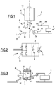
- FIG. 1 a first embodiment of a contactor-circuit breaker device 2 according to the invention.
- the device 2 comprises a mechanical switch 4 and a current cut-off module 6 including a semiconductor device 8.
- the switch mechanical 4 comprises two pairs of contacts 10, 12, each pair of contacts 10, 12 comprising a fixed contact 14, 16 and a movable contact 18, 20.
- the contactor-circuit breaker device 2 is able to establish or interrupt the current flowing in an electric circuit 22 connected to a load such as a motor.
- the electric circuit 22 is schematized in the figures by an electric line L.
- the contactor-circuit-breaker device 2 further comprises a support member 24 of the movable contacts 18, 20 and a device 26 for moving the support member 24. It further comprises a stop piece 28.
- the fixed contacts 14, 16 of the pairs 10, 12 of contacts are arranged in series of the electrical circuit 22.
- the movable contacts 18, 20 of the pairs 10, 12 of contacts are mechanically and electrically connected to each other via the organ support 24.
- Each fixed contact 14, 16 and each movable contact 18, 20 of the same pair 10, 12 of contacts are arranged facing one another, so that they are adapted to be placed in mechanical and electrical contact. with each other.
- the mechanical switch 4 is movable in translation along a translation axis X and suitable for switching between a closing configuration of the electric circuit 22 and an opening configuration of the electrical circuit 22.
- the fixed contacts 14, 16 and movable 18, 20 of each pair 10, 12 of contacts are in mechanical contact so that a current is able to flow between the two pairs 10, 12 of contacts.
- the fixed contacts 14, 16 and movable 18, 20 of at least one pair 10, 12 are spaced apart from each other.
- the mechanical switch 4 is further adapted to achieve a maximum opening configuration.
- the maximum aperture configuration is represented on the figures 4 and 12 and will be described in more detail later.
- the contactor-circuit breaker device 2 advantageously comprises a housing 30 and a recording device 31, visible on the figure 12 .
- the housing 30 is adapted to receive the recording member 31 so as to block the switch 4, and only when the switch 4 is in the maximum opening configuration.
- the recording member 31 is for example a padlock.
- the lock 31 connects the mechanical switch 4 to a fixed support (not shown) via the housing 30, allowing the mechanical switch 4 to be maintained in its maximum opening configuration.
- the current breaking module 6 comprises the semiconductor device 8, a diode bridge 32, and a varistor 34.
- the semiconductor device 8, the diode bridge 32, and the varistor 34 are connected in parallel.
- the semiconductor device 8 is for example an insulated gate bipolar transistor 36 (IGBT, of the English “Insulated Gate Bipolar Transistor”).
- the semiconductor device 8 is a bipolar transistor, a MOSFET (Metal Oxide Semiconductor Field Effect Transistor), a thyristor GTO (English Gate Turn-Off), or a thyristor MCT (Metal Oxide Semiconductor Controlled Thyristor).
- the semiconductor device 8 is lockable and bootable by the control, i.e., it is capable of switching from a switched state to a controllably locked state.
- the breaking module 6 is thus able to pass from an on state, in which a current flows in the breaking module 6, to a blocked state, in which no current flows in the breaking module 6.
- the breaking module 6 is able to switch the current from the electric circuit 22 to the breaking module 6 and to interrupt the current flowing in the circuit electric 22.
- the breaking module 6 is connected to the abutment piece 28, via a rigid conductor 38.
- the support member 24 is formed of an arm 42 on which are disposed the movable contacts 18, 20 of each pair 10, 12.
- the movement apparatus 26 comprises an armature 44.
- the armature 44 is advantageously connected to the support member 24 via, for example, a link module 46 shown on the FIG. figures 3 and 4 and which will be described in more detail later.
- the motion apparatus 26 is, for example, an electromagnet.
- the electromagnet comprises a fixed body 50 comprising at least one coil (not shown) and / or at least one permanent magnet, and the armature 44.
- the electromagnet comprises for example a single coil.
- the armature 44 extends along the translation axis X and is movable in translation along the translation axis X relative to the fixed body 50, under the effect of the magnetic field created by the coil.
- the armature 44 thus has a rectilinear trajectory with respect to the fixed body 50 of the electromagnet.
- the translation of the armature 44 thus causes the translation and / or rotation of the support member 24 of the movable contacts 18, 20.
- the armature 44 is adapted to put in translation movement and / or rotating the support member 24 so that the support member 24 switches between the closure configuration and the opening configuration of the electrical circuit 22.
- the support member 24 is movable in translation along the translation axis X.
- the support member 24 moves from the closure configuration to the opening configuration, for example by a translational movement. along the vertical axis X.
- the support member 24 is furthermore preferably rotatable relative to an axis of rotation Y perpendicular to the direction of translation of the support member 24, that is to say perpendicular to the axis of rotation. translation X.
- the support member 24 is thus able to switch from the closure configuration to the maximum opening configuration by performing, for example, a translation along the vertical axis X and / or a rotation relative to the rotation axis Y.
- connection module 46 adapted to connect the support member 24 to the movement apparatus 26 is shown in greater detail.
- connection module 46 comprises a side wall 52, a bottom wall 54 and an upper wall 56.
- the upper wall 56 is opposite to the bottom wall 54.
- the connection module 46 further comprises a swivel pivot 58 of the support member 24 and a return member 60 of the support member 24 towards the frame 44, more precisely to the upper wall 56, for example a spring.
- connection module 46 further comprises a stop block A adapted to limit the rotation of the support member 24.
- the upper wall 56 is fixed to the armature 44 and extends perpendicularly to the translation axis X.
- the spring 60 extends parallel to the translation axis X and has a first end 62 and a second end 64.
- the first end 62 is connected to the upper wall 56 of the connection module 46 and the second end 64 is connected to the support member 24 at an anchoring point P of the support member 24.
- the pivot 58 advantageously extends parallel to the axis of rotation Y, and for example protrudes from the bottom wall 54 to the upper wall 56.
- the pivot 58 comprises a rest edge R which extends from the same way parallel to the axis of rotation Y.
- the support member 24 rests on the pivot 58, more precisely on the rest edge R of the support member 24.
- the anchoring point P is located at a distance from the translation axis X, that is to say that the anchoring point P is offset with respect to the translation axis X.
- the pivot 58 and the rest edge R of the pivot 58 are located on the translation axis X.
- the switch 4 is in the opening configuration and on the figure 4 , the switch is in the maximum aperture configuration.
- the mechanical switch 4 is able to reach a maximum opening configuration.
- the fixed contact 14 and movable contact 18 of a first pair 10 from the pairs 10, 12, 10 of said cut pair are at a maximum distance d c, said cutoff distance d c , one of the other.
- the movable contact 18 of the breaking pair 10 is then in mechanical contact with the abutment piece 28.
- the fixed contact 16 and the movable contact 20 of the second pair 12 of contacts, said sectioning pair 12 are at a maximum distance d s , said sectioning distance d s , one of the other.
- the characteristic that the support member 24 is rotatable has the advantage of not having to ensure that the maximum stroke of the electromagnet 46 is equal to the disconnection distance, which would be particularly expensive.
- the sectioning distance d s is greater than the breaking distance d c .
- the disconnection distance d s must be particularly important to allow efficient and reliable isolation of the electrical circuit 22.
- the disconnection distance d s is between 1 mm and 12 mm, preferably between 5 and 9 mm, and in particular equal to 6 mm.
- the cut-off distance d c is between 0.1 mm and 3 mm, and in particular equal to 1 mm.
- the distance traveled by the movable contact 18 between the closure configuration and the maximum opening configuration is between 0.2 mm and 1.5 mm.
- the breaking module 6 is connected in parallel with the pair of contacts in which the distance between the movable contact 18 and the fixed contact 14 is the smallest when the switch 4 is in the opening configuration. Max.
- the cutoff module 6 is connected in parallel with the cutoff pair. A rapid opening of the mechanical switch 4 and therefore rapid switching of the fault current from the electrical circuit 22 to the breaking module 6 is ensured.
- the movable contacts 18, 20 are located on either side and equidistant from the axis of rotation Y.
- the abutment piece 28 is able to stop the translation and / or rotation movement of the support member 24 when the switch 4 reaches the maximum opening configuration.
- the abutment piece 28 is disposed facing the movable contact 18 of the cutoff pair 10, on the side of the movable contact 18 opposite the corresponding fixed contact 14 of the same cutoff pair.
- the abutment piece 28 is adapted to be brought into contact with the movable contact 18 of the pair of contacts in which the distance between the movable contact 18 and the fixed contact 14 is the smallest when the mechanical switch 4 is in its maximum aperture configuration.
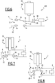
- a second embodiment of the device 102 which does not form part of the invention is represented on the figure 5 .
- the cut-off module 6 is connected to the support member 24, via a metal braid 66.
- the cut-off module 6 is then connected to the device 24 and therefore to the movable contacts 14, 18 at all times, that the switch is in the configuration of closing, opening or maximum opening.
- a third embodiment of the device 202 according to the invention is represented on the figure 6 .
- the movable contacts are located on the same side of the axis of rotation Y of the support member 24.
- the support member 24 comprises an electrical connection element 68.
- the electrical connecting element 68 is located on the opposite side to the side of the movable contacts 18, 20.
- the electrical connecting element 68 is able to be brought into contact with the abutment piece 28.
- the curve A represents the evolution of the current flowing in the breaking module 6
- the curve B represents the evolution of the current passing through the contacts 14, 18 of the cut-off pair
- the curve C represents the evolution current passing through the contacts 16, 20 of the sectioning pair 12
- the curve D represents the evolution of the voltage across the device 2.
- the curves A and B are offset vertically with respect to the curve C.
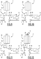
- the mechanical switch 4 In the closed position, the mechanical switch 4 is in its metallic conduction configuration, that is to say that the fixed contacts 14, 16 and movable 18, 20 of each pair 10, 12 are in mechanical contact. This phase of operation is represented on the figure 7 . No current flows in the breaking module 6, as can be seen in Part VII of the figure 16 . In the closed position, the breaking module 6 is indifferently in the off or on state.
- the moving apparatus 26 sets the support member 24 in motion.
- the support member 24 is moved through the armature 44 so that the mechanical switch 4 moves from the closure configuration to the opening configuration in which the movable contacts 18, 20 and the fixed contacts 14, 16 of the pairs 10, 12 of contacts are separated by a non-zero distance. At least one electric arc then appears between at least one of the movable contacts 18, 20 and at least one of the fixed contacts 14, 16 of the pairs 10, 12. This operating phase is represented on the figure 8 .
- an arc voltage V arc then appears between each movable contact 18, 20 and each fixed contact 14, 16 during their separation.
- the voltage across the device 2 is then equal to 2 * V arc and corresponds to the arcs present in each pair 10, 12 of contacts.
- the device 2 continues to conduct the current of the electric circuit 22.
- the support member 24 continues its rectilinear stroke until the movable contact 18 of the cutoff pair 10 is in contact with the abutment piece 28.
- This configuration is shown in FIG. figure 9 , and corresponds to Part IX of the figure 16 .
- the semiconductor device 8 is The semiconductor device 8 is dimensioned to present a voltage V ON less than V arc .
- the electric arc located in the cut-off pair 10 allows the current flowing in the electric circuit 22 to switch gradually towards the breaking module 6, the semiconductor device 8 being in an on state allowing the current to flow in the circuit. cutoff module 6.
- the fault current initially flowing in the electric circuit 22 is progressively switched to the breaking module 6 connected in parallel with the cut-off pair 10, via the stop piece 28.
- the semiconductor device 8 is turned on from the operating phase shown in FIG. figure 8 and Part VIII of the figure 16 .
- the support member 24 rotates about the axis of rotation Y.
- the rotation of the support member 24 is consecutive to the travel of the armature 44 exceeding the abutment dimension of the contact 18 on the part 28
- the abutment piece 28 is able to cause a rotational movement complementary to the translational movement, so that the switch 4 has, in the maximum opening configuration, a maximum opening greater than the travel of
- the switch 4 switches to the maximum open configuration, i.e. the contacts 16, 20 of the sectioning pair 12 are separated from the disconnection distance. d s for which no current can not flow between the two contacts 16, 20.
- phase XI the semiconductor device 8 is blocked so as to force the passage of the current in the varistor 34.
- the varistor 34 has a voltage V var at its terminals.
- the current in the device 2 decreases rapidly as shown in part XI of the figure 16 until it becomes null, as shown in Part XII of the figure 16 .
- the voltage across the device is equal to V arc + V var .
- the voltage across the device is equal to the supply voltage across the load.
- the device 2 is in the maximum opening configuration ensuring sectioning.
- the device 2 is then for example blocked in this maximum opening configuration via the logger 31 received in the housing 30.
- the device 2 is then locked in the open position. This consignment ensures the safety of people downstream of the device during human interventions.
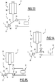
- the operation of the device 2 closing that is to say the closure of the device 2 when the circuit breaker is tripped or the contactor closes, is carried out as described below, with reference to FIGS. Figures 13 to 15 and at the figure 16 .
- the device 2 is, in the initial state, in the configuration shown in FIG. figure 12 .
- the semiconductor device 8 is turned on, so that the current is restored in the device 2. This phase corresponds to the part XIII ' of the figure 16 .
- the voltage across the device 2 is equal to V ON . In this way, no electric arc appears between the contacts 16, 20 of the sectioning pair 12.
- the movable contact 18 continues its course to be joined to the fixed contact 14. As soon as the movable contact 18 and the fixed contact 14 are contiguous, and as visible in the part XV of the figure 16 , the current begins to decrease in the breaking module 6. The voltage across the device 2 during phase XV, when the current is still non-zero, is zero.
- the current flowing in the device 6 decreases to zero.
- the current is then totally transferred to a metallic conduction.
- the device 2 is then found in the configuration represented on the figure 7 and in phase VII of the figure 16 .
- the device 2 is closed, the current flows in the electric circuit 22 and no longer circulates in the breaking module 6.
- This mode of operation thus makes it possible to preserve the contacts 16, 20 of the sectioning pair 12 of the erosion due to the electric arcs, and to improve the electrical endurance of the device according to the invention.
- the operation of the second embodiment of the device 102 is similar to the operation of the first embodiment of the device 2, with the difference that the cut-off module 6 is permanently connected to the support member 24.
- the operation of the third embodiment of the device 202 is similar to the operation of the first embodiment of the device 2, with the difference that in the maximum aperture configuration, the abutment piece 28 is in mechanical contact with the connecting element
- the movable contact 18 and the abutment piece 28 are in electrical contact via the support member 24 and the electrical connection element 68.
- the position of the abutment piece 28 can be optimized to minimize the arc duration between the contacts 14, 18 of the breaking pair.
- the abutment piece 28 and the electrical connection element 68 are for example in permanent contact.
- the contactor-circuit breaker device makes it possible, thanks to the mobility in translation and / or in rotation of the support member 24, to be implemented on contactors-breakers of the state of the art. in an easy way.
- the device according to the invention makes it possible to obtain a fast opening phase and consequently to obtain a fast and efficient switching of the current when a fault current appears in the electric circuit 22.
Landscapes
- Breakers (AREA)
- Driving Mechanisms And Operating Circuits Of Arc-Extinguishing High-Tension Switches (AREA)
Claims (13)
- Schaltschützvorrichtung (2, 102, 202), umfassend:- einen mechanischen Schalter (4), der mindestens zwei Kontaktpaare (10, 12) aufweist, wobei jedes Kontaktpaar (10, 12) einen Festkontakt (14, 16) und einen beweglichen Kontakt (18, 20) umfasst, die geeignet sind, in Kontakt gebracht zu werden, die Festkontakte (14, 16) in Reihe mit einem elektrischen Schaltkreis (22) verbunden sind, der mechanische Schalter (4) geeignet ist, zwischen einer Stellung des Schließens des elektrischen Schaltkreises (22), in dem die Festkontakte (14, 16) und die beweglichen Kontakte (18, 20) jedes Kontaktpaars (10, 12) in mechanischem Kontakt sind, und einer Stellung des Öffnens des elektrischen Schaltkreises (22), in dem die Festkontakte (14, 16) und die beweglichen Kontakte (18, 20) mindestens eines Kontaktpaares (10, 12) voneinander beabstandet sind, zu wechseln;- ein Trägerelement (24) für die beweglichen Kontakte (18, 20);- ein Modul (6) zur Stromunterbrechung, das eine Halbleitervorrichtung (8) aufweist, wobei das Unterbrechungsmodul (6) zu einem der Kontaktpaare (10, 12) parallel geschaltet sind, wenn der Schalter (4) in der Offenstellung ist, und geeignet ist, den von dem elektrischen Schaltkreis (22) kommenden Strom zu dem Unterbrechungsmodul (6) zu schalten und den in dem elektrischen Schaltkreis (22) fließenden Strom zu unterbrechen, wenn der Schalter (4) in der Offenstellung ist und ein Lichtbogen in mindestens einem der Kontaktpaare (10, 12) erscheint; und- eine Vorrichtung (26) zum Bewegen des Trägerelements (24), die einen Anker (44) umfasst, wobei die Vorrichtung (26) zum Bewegen geeignet ist, den Anker (44) in eine Längsbewegung zu versetzen, derart, dass das Trägerelement (24) zwischen der Stellung des Schließens und der Stellung des Öffnens des elektrischen Schaltkreises (22) durch eine Längsbewegung und/oder Drehbewegung umgestellt wird,wobei der Schalter (4) geeignet ist, eine maximale Offenstellung zu erreichen, und die Vorrichtung (2) ein Anschlagteil (28) aufweist, das geeignet ist, die Längsbewegung und/oder die Drehung des Trägerelements (24) zu stoppen, wenn der Schalter (4) die maximale Offenstellung erreicht,
wobei das Anschlagteil (28) geeignet ist, in Kontakt mit dem beweglichen Kontakt (18) des Kontaktpaares (10), bei dem die Entfernung zwischen dem beweglichen Kontakt (18) und dem Festkontakt (14) am kleinsten ist, gesetzt zu werden, wenn der Schalter (4) in seiner maximalen Offenstellung ist,
dadurch gekennzeichnet, dass das Unterbrechungsmodul (6) mit dem Anschlagteil (28) verbunden ist. - Vorrichtung (2, 102, 202) nach Anspruch 1, dadurch gekennzeichnet, dass das Anschlagteil (28) geeignet ist, eine Drehbewegung komplementär zur Längsbewegung zu verursachen, derart, dass der Schalter (4) in seiner maximalen Offenstellung eine maximale Öffnung größer als der Hub der Vorrichtung (26) zum Bewegen aufweist.
- Vorrichtung (2, 102, 202) nach einem der Ansprüche 1 bis 2, dadurch gekennzeichnet, dass das Trägerelement (24) translatorisch in Bezug auf eine Längsachse (X) und rotatorisch in Bezug auf eine Drehachse (Y) beweglich ist, wobei die Drehachse (Y) senkrecht zur Längsachse (X) liegt.
- Vorrichtung (2, 102, 202) nach einem der Ansprüche 1 bis 3, dadurch gekennzeichnet, dass, wenn der Schalter (4) in seiner maximalen Offenstellung ist, der Abstand zwischen jedem Festkontakt (14, 16) und jedem beweglichen Kontakt (18, 20) für jedes Kontaktpaar (10, 12) unterschiedlich ist, und dass das Unterbrechungsmodul (6) parallel zu dem Kontaktpaar (10) geschaltet ist, bei dem der Abstand zwischen dem beweglichen Kontakt (18) und dem Festkontakt (14) am kleinsten ist.
- Vorrichtung (2, 202) nach einem beliebigen der Ansprüche 1 bis 4, dadurch gekennzeichnet, dass das Unterbrechungsmodul (6) mit dem Anschlagteil (28) über einen starren Leiter (38) verbunden ist.
- Vorrichtung (2, 102) nach einem beliebigen der Ansprüche 3 bis 5, dadurch gekennzeichnet, dass die beweglichen Kontakte beidseitig der Drehachse (Y) liegen.
- Vorrichtung (2, 102) nach Anspruch 6, dadurch gekennzeichnet, dass die beweglichen Kontakte mit gleichem Abstand zur Drehachse (Y) angeordnet sind.
- Vorrichtung (202) nach einem der Ansprüche 3 bis 5, dadurch gekennzeichnet, dass sie ein elektrisches Verbindungselement (68) aufweist, und dass die beweglichen Kontakte (18, 20) an derselben Seite der Drehachse (Y) liegen.
- Vorrichtung (202) nach einem der Ansprüche 1 bis 8, dadurch gekennzeichnet, dass das Anschlagteil (28) in ständigem Kontakt mit dem elektrischen Verbindungselement (68) ist.
- Vorrichtung (2, 102) nach einem der Ansprüche 3 bis 9, dadurch gekennzeichnet, dass die Vorrichtung (26) zum Bewegen ein Verbindungsmodul (46) umfasst, das geeignet ist, das Trägerelement (24) mit dem Anker (44) zu verbinden, wobei das Verbindungsmodul (46) einen Schwenkpunkt (58) zum Schwenken des Trägerelements (24) und ein Element (60) zum Rückstellen des Trägerelements (24) zu dem Anker (44) umfasst, wobei der Schwenkpunkt (58) in der Längsachse (X) liegt und das Rückstellelement (60) mit Abstand zu der Längsachse (X) liegt.
- Vorrichtung (2, 102) nach Anspruch 10, dadurch gekennzeichnet, dass das Verbindungsmodul (46) einen Anhaltebock (A) umfasst, der geeignet ist, die Drehung des Trägerelements (24) zu begrenzen.
- Vorrichtung (2, 102, 202) nach einem beliebigen der vorhergehenden Ansprüche, dadurch gekennzeichnet, dass die Vorrichtung (26) zum Bewegen ein Elektromagnet ist.
- Vorrichtung (2, 102, 202) nach einem beliebigen der Ansprüche 1 bis 12, dadurch gekennzeichnet, dass die Vorrichtung (2) einen Aufnahmeraum (30) und ein Konsignationselement (31) umfasst, wobei der Aufnahmeraum geeignet ist, das Konsignationselement (31) aufzunehmen, derart, dass der Schalter (4) nur in der maximalen Offenstellung blockiert wird.
Applications Claiming Priority (1)
| Application Number | Priority Date | Filing Date | Title |
|---|---|---|---|
| FR1262442A FR3000284B1 (fr) | 2012-12-20 | 2012-12-20 | Dispositif contacteur-disjoncteur |
Publications (2)
| Publication Number | Publication Date |
|---|---|
| EP2747103A1 EP2747103A1 (de) | 2014-06-25 |
| EP2747103B1 true EP2747103B1 (de) | 2017-05-10 |
Family
ID=48083255
Family Applications (1)
| Application Number | Title | Priority Date | Filing Date |
|---|---|---|---|
| EP13197642.5A Active EP2747103B1 (de) | 2012-12-20 | 2013-12-17 | Kontaktschalter-Schutzschalter-Vorrichtung |
Country Status (5)
| Country | Link |
|---|---|
| US (1) | US9508500B2 (de) |
| EP (1) | EP2747103B1 (de) |
| CN (1) | CN103887122B (de) |
| ES (1) | ES2636591T3 (de) |
| FR (1) | FR3000284B1 (de) |
Families Citing this family (6)
| Publication number | Priority date | Publication date | Assignee | Title |
|---|---|---|---|---|
| EP3360149B1 (de) | 2015-10-08 | 2020-01-15 | ABB Schweiz AG | Schaltvorrichtung |
| FR3067165A1 (fr) | 2017-05-30 | 2018-12-07 | Leach International Europe | Systeme d'hybridation pour courant continu haute tension |
| GB201820592D0 (en) | 2018-12-18 | 2019-01-30 | Eaton Intelligent Power Ltd | Switching device for guiding and switching of load currents |
| US11901140B2 (en) * | 2022-05-16 | 2024-02-13 | Rockwell Automation Technologies, Inc. | Hybrid circuit breaker with solid state devices |
| US12160098B2 (en) | 2022-08-16 | 2024-12-03 | Rockwell Automation Technologies, Inc. | Hybrid circuit breaker with solid-state devices |
| FR3146235A1 (fr) * | 2023-02-28 | 2024-08-30 | Airbus Operations (S.A.S.) | Contacteur électrique adapté pour les circuits électriques de forte puissance, aéronef comportant un circuit électrique intégrant au moins un tel contacteur électrique |
Family Cites Families (8)
| Publication number | Priority date | Publication date | Assignee | Title |
|---|---|---|---|---|
| US3350525A (en) * | 1965-01-25 | 1967-10-31 | Gen Electric | Circuit breaker resetting mechanism |
| DE3137321A1 (de) * | 1981-09-19 | 1983-04-07 | Brown, Boveri & Cie Ag, 6800 Mannheim | "elektrisches schaltgeraet" |
| US4709294A (en) * | 1984-08-27 | 1987-11-24 | In Suk Kim | Device for contact protection and arc prevention of a switch |
| TW293130B (de) * | 1994-03-10 | 1996-12-11 | Mitsubishi Electric Corp | |
| JPH08148072A (ja) * | 1994-11-18 | 1996-06-07 | Alps Electric Co Ltd | ブレーカ内蔵スイッチ |
| CN101188176B (zh) * | 2007-11-27 | 2010-08-11 | Tcl低压电器(无锡)有限公司 | 能正确显示塑壳断路器触头合分的装置 |
| EP2465129B1 (de) * | 2009-08-13 | 2013-04-24 | ABB Research Ltd. | Hybridschutzschalter |
| US8598477B2 (en) * | 2009-10-13 | 2013-12-03 | Barton L. Garvin | Universal switch restraint device |
-
2012
- 2012-12-20 FR FR1262442A patent/FR3000284B1/fr not_active Expired - Fee Related
-
2013
- 2013-12-17 ES ES13197642.5T patent/ES2636591T3/es active Active
- 2013-12-17 EP EP13197642.5A patent/EP2747103B1/de active Active
- 2013-12-18 US US14/132,439 patent/US9508500B2/en active Active
- 2013-12-20 CN CN201310711387.7A patent/CN103887122B/zh active Active
Also Published As
| Publication number | Publication date |
|---|---|
| FR3000284B1 (fr) | 2016-05-13 |
| ES2636591T3 (es) | 2017-10-06 |
| CN103887122B (zh) | 2018-04-24 |
| CN103887122A (zh) | 2014-06-25 |
| FR3000284A1 (fr) | 2014-06-27 |
| US20140175060A1 (en) | 2014-06-26 |
| EP2747103A1 (de) | 2014-06-25 |
| US9508500B2 (en) | 2016-11-29 |
Similar Documents
| Publication | Publication Date | Title |
|---|---|---|
| EP2747103A1 (de) | Kontaktschalter-Schutzschalter-Vorrichtung | |
| EP2466601B1 (de) | Unterbrechungsvorrichtung mit Monitor mit Lichtbogenunterbrechung | |
| EP4341972B1 (de) | Elektrische geräte und schutzsysteme | |
| EP0042778B1 (de) | Einpol- und Nulleiter-Kleinschalter | |
| FR2738664A1 (fr) | Dispositif hybride utilisant l'effet miller pour la protection des contacts electriques contre la formation d'arcs | |
| EP1855300B1 (de) | Trennschalter für einen Wechselstromschalter, der von einem Servomotor betätigt wird | |
| EP1185995A1 (de) | Steuervorrichtung zum öffnen und/oder zum schliessen, insbesondere für ein schaltgerät wie ein schutzschalter, und ein schutzschalter ausgerüstet mit dieser vorrichtung | |
| CN102543602A (zh) | 模制管壳式断路器的脱扣单元和有该脱扣单元的该断路器 | |
| EP3699942B1 (de) | Einschaltsystem einer vakuumschaltröhre | |
| EP1901320A1 (de) | Kontaktvorrichtung für ein Elektrogerät und Elektrogerät mit derartiger Vorrichtung | |
| EP1485931B1 (de) | Elektrische einrichtung mit einem gesteuerten piezoelektrischen betätigungsglied | |
| FR2982995A1 (fr) | Dispositif de coupure a ecran pour contacteur | |
| EP2842151B1 (de) | Aktuatorsschaltkreis für lastschalter | |
| FR2981789A1 (fr) | Dispositif de coupure electrique comportant un pont mobile de contact | |
| WO2010018030A1 (fr) | Actionneur electromagnetique hybride a bobine fixe | |
| EP3982386B1 (de) | Optimierter stromnetzschalter | |
| EP3709323B1 (de) | Elektrisches gerät zur stromverbindung oder -unterbrechung in einem elektrischen schaltkreis | |
| EP0310469A1 (de) | Schutzschalter mit Blende zum Unterbrechen des Lichtbogens | |
| EP2346157B1 (de) | Klemmvorrichtung zum PHASENUMkehr | |
| FR2587140A1 (fr) | Dispositif d'assistance a la commutation electrique, notamment pour relais a contacts ou contacteurs ou autres moyens de telecommande similaires | |
| WO2005001868A1 (fr) | Appareil electrique interrupteur a plusieurs actionneurs. | |
| EP0794547A1 (de) | Elektrischer Schutzschalter mit elektromagnetischen Betätiger und Betätigungsmechanismus | |
| EP0930632A1 (de) | Elektromagnetisch betätigtes Schaltgerät | |
| FR3060226A1 (fr) | Appareil electrique de mise a la terre, comprenant une derivation isolante, et son procede de fermeture | |
| FR3060195A1 (fr) | Appareil de connexion electrique a derivation de coupure d'arc, et procede d'ouverture de cet appareil |
Legal Events
| Date | Code | Title | Description |
|---|---|---|---|
| PUAI | Public reference made under article 153(3) epc to a published international application that has entered the european phase |
Free format text: ORIGINAL CODE: 0009012 |
|
| 17P | Request for examination filed |
Effective date: 20131217 |
|
| AK | Designated contracting states |
Kind code of ref document: A1 Designated state(s): AL AT BE BG CH CY CZ DE DK EE ES FI FR GB GR HR HU IE IS IT LI LT LU LV MC MK MT NL NO PL PT RO RS SE SI SK SM TR |
|
| AX | Request for extension of the european patent |
Extension state: BA ME |
|
| R17P | Request for examination filed (corrected) |
Effective date: 20140930 |
|
| RBV | Designated contracting states (corrected) |
Designated state(s): AL AT BE BG CH CY CZ DE DK EE ES FI FR GB GR HR HU IE IS IT LI LT LU LV MC MK MT NL NO PL PT RO RS SE SI SK SM TR |
|
| GRAP | Despatch of communication of intention to grant a patent |
Free format text: ORIGINAL CODE: EPIDOSNIGR1 |
|
| INTG | Intention to grant announced |
Effective date: 20161212 |
|
| GRAS | Grant fee paid |
Free format text: ORIGINAL CODE: EPIDOSNIGR3 |
|
| GRAA | (expected) grant |
Free format text: ORIGINAL CODE: 0009210 |
|
| AK | Designated contracting states |
Kind code of ref document: B1 Designated state(s): AL AT BE BG CH CY CZ DE DK EE ES FI FR GB GR HR HU IE IS IT LI LT LU LV MC MK MT NL NO PL PT RO RS SE SI SK SM TR |
|
| REG | Reference to a national code |
Ref country code: GB Ref legal event code: FG4D Free format text: NOT ENGLISH |
|
| REG | Reference to a national code |
Ref country code: AT Ref legal event code: REF Ref document number: 893118 Country of ref document: AT Kind code of ref document: T Effective date: 20170515 Ref country code: CH Ref legal event code: EP |
|
| REG | Reference to a national code |
Ref country code: IE Ref legal event code: FG4D Free format text: LANGUAGE OF EP DOCUMENT: FRENCH |
|
| REG | Reference to a national code |
Ref country code: DE Ref legal event code: R096 Ref document number: 602013020892 Country of ref document: DE |
|
| REG | Reference to a national code |
Ref country code: NL Ref legal event code: MP Effective date: 20170510 |
|
| REG | Reference to a national code |
Ref country code: LT Ref legal event code: MG4D |
|
| REG | Reference to a national code |
Ref country code: ES Ref legal event code: FG2A Ref document number: 2636591 Country of ref document: ES Kind code of ref document: T3 Effective date: 20171006 |
|
| REG | Reference to a national code |
Ref country code: AT Ref legal event code: MK05 Ref document number: 893118 Country of ref document: AT Kind code of ref document: T Effective date: 20170510 |
|
| PG25 | Lapsed in a contracting state [announced via postgrant information from national office to epo] |
Ref country code: AT Free format text: LAPSE BECAUSE OF FAILURE TO SUBMIT A TRANSLATION OF THE DESCRIPTION OR TO PAY THE FEE WITHIN THE PRESCRIBED TIME-LIMIT Effective date: 20170510 Ref country code: NO Free format text: LAPSE BECAUSE OF FAILURE TO SUBMIT A TRANSLATION OF THE DESCRIPTION OR TO PAY THE FEE WITHIN THE PRESCRIBED TIME-LIMIT Effective date: 20170810 Ref country code: FI Free format text: LAPSE BECAUSE OF FAILURE TO SUBMIT A TRANSLATION OF THE DESCRIPTION OR TO PAY THE FEE WITHIN THE PRESCRIBED TIME-LIMIT Effective date: 20170510 Ref country code: LT Free format text: LAPSE BECAUSE OF FAILURE TO SUBMIT A TRANSLATION OF THE DESCRIPTION OR TO PAY THE FEE WITHIN THE PRESCRIBED TIME-LIMIT Effective date: 20170510 Ref country code: HR Free format text: LAPSE BECAUSE OF FAILURE TO SUBMIT A TRANSLATION OF THE DESCRIPTION OR TO PAY THE FEE WITHIN THE PRESCRIBED TIME-LIMIT Effective date: 20170510 Ref country code: GR Free format text: LAPSE BECAUSE OF FAILURE TO SUBMIT A TRANSLATION OF THE DESCRIPTION OR TO PAY THE FEE WITHIN THE PRESCRIBED TIME-LIMIT Effective date: 20170811 |
|
| PG25 | Lapsed in a contracting state [announced via postgrant information from national office to epo] |
Ref country code: RS Free format text: LAPSE BECAUSE OF FAILURE TO SUBMIT A TRANSLATION OF THE DESCRIPTION OR TO PAY THE FEE WITHIN THE PRESCRIBED TIME-LIMIT Effective date: 20170510 Ref country code: IS Free format text: LAPSE BECAUSE OF FAILURE TO SUBMIT A TRANSLATION OF THE DESCRIPTION OR TO PAY THE FEE WITHIN THE PRESCRIBED TIME-LIMIT Effective date: 20170910 Ref country code: LV Free format text: LAPSE BECAUSE OF FAILURE TO SUBMIT A TRANSLATION OF THE DESCRIPTION OR TO PAY THE FEE WITHIN THE PRESCRIBED TIME-LIMIT Effective date: 20170510 Ref country code: SE Free format text: LAPSE BECAUSE OF FAILURE TO SUBMIT A TRANSLATION OF THE DESCRIPTION OR TO PAY THE FEE WITHIN THE PRESCRIBED TIME-LIMIT Effective date: 20170510 Ref country code: BG Free format text: LAPSE BECAUSE OF FAILURE TO SUBMIT A TRANSLATION OF THE DESCRIPTION OR TO PAY THE FEE WITHIN THE PRESCRIBED TIME-LIMIT Effective date: 20170810 Ref country code: NL Free format text: LAPSE BECAUSE OF FAILURE TO SUBMIT A TRANSLATION OF THE DESCRIPTION OR TO PAY THE FEE WITHIN THE PRESCRIBED TIME-LIMIT Effective date: 20170510 Ref country code: PL Free format text: LAPSE BECAUSE OF FAILURE TO SUBMIT A TRANSLATION OF THE DESCRIPTION OR TO PAY THE FEE WITHIN THE PRESCRIBED TIME-LIMIT Effective date: 20170510 |
|
| REG | Reference to a national code |
Ref country code: FR Ref legal event code: PLFP Year of fee payment: 5 |
|
| PG25 | Lapsed in a contracting state [announced via postgrant information from national office to epo] |
Ref country code: EE Free format text: LAPSE BECAUSE OF FAILURE TO SUBMIT A TRANSLATION OF THE DESCRIPTION OR TO PAY THE FEE WITHIN THE PRESCRIBED TIME-LIMIT Effective date: 20170510 Ref country code: CZ Free format text: LAPSE BECAUSE OF FAILURE TO SUBMIT A TRANSLATION OF THE DESCRIPTION OR TO PAY THE FEE WITHIN THE PRESCRIBED TIME-LIMIT Effective date: 20170510 Ref country code: DK Free format text: LAPSE BECAUSE OF FAILURE TO SUBMIT A TRANSLATION OF THE DESCRIPTION OR TO PAY THE FEE WITHIN THE PRESCRIBED TIME-LIMIT Effective date: 20170510 Ref country code: RO Free format text: LAPSE BECAUSE OF FAILURE TO SUBMIT A TRANSLATION OF THE DESCRIPTION OR TO PAY THE FEE WITHIN THE PRESCRIBED TIME-LIMIT Effective date: 20170510 Ref country code: SK Free format text: LAPSE BECAUSE OF FAILURE TO SUBMIT A TRANSLATION OF THE DESCRIPTION OR TO PAY THE FEE WITHIN THE PRESCRIBED TIME-LIMIT Effective date: 20170510 |
|
| REG | Reference to a national code |
Ref country code: DE Ref legal event code: R097 Ref document number: 602013020892 Country of ref document: DE |
|
| PG25 | Lapsed in a contracting state [announced via postgrant information from national office to epo] |
Ref country code: SM Free format text: LAPSE BECAUSE OF FAILURE TO SUBMIT A TRANSLATION OF THE DESCRIPTION OR TO PAY THE FEE WITHIN THE PRESCRIBED TIME-LIMIT Effective date: 20170510 |
|
| PLBE | No opposition filed within time limit |
Free format text: ORIGINAL CODE: 0009261 |
|
| STAA | Information on the status of an ep patent application or granted ep patent |
Free format text: STATUS: NO OPPOSITION FILED WITHIN TIME LIMIT |
|
| 26N | No opposition filed |
Effective date: 20180213 |
|
| PG25 | Lapsed in a contracting state [announced via postgrant information from national office to epo] |
Ref country code: SI Free format text: LAPSE BECAUSE OF FAILURE TO SUBMIT A TRANSLATION OF THE DESCRIPTION OR TO PAY THE FEE WITHIN THE PRESCRIBED TIME-LIMIT Effective date: 20170510 |
|
| REG | Reference to a national code |
Ref country code: CH Ref legal event code: PL |
|
| REG | Reference to a national code |
Ref country code: IE Ref legal event code: MM4A |
|
| PG25 | Lapsed in a contracting state [announced via postgrant information from national office to epo] |
Ref country code: MT Free format text: LAPSE BECAUSE OF FAILURE TO SUBMIT A TRANSLATION OF THE DESCRIPTION OR TO PAY THE FEE WITHIN THE PRESCRIBED TIME-LIMIT Effective date: 20170510 Ref country code: LU Free format text: LAPSE BECAUSE OF NON-PAYMENT OF DUE FEES Effective date: 20171217 |
|
| REG | Reference to a national code |
Ref country code: BE Ref legal event code: MM Effective date: 20171231 |
|
| PG25 | Lapsed in a contracting state [announced via postgrant information from national office to epo] |
Ref country code: IE Free format text: LAPSE BECAUSE OF NON-PAYMENT OF DUE FEES Effective date: 20171217 |
|
| PG25 | Lapsed in a contracting state [announced via postgrant information from national office to epo] |
Ref country code: BE Free format text: LAPSE BECAUSE OF NON-PAYMENT OF DUE FEES Effective date: 20171231 Ref country code: CH Free format text: LAPSE BECAUSE OF NON-PAYMENT OF DUE FEES Effective date: 20171231 Ref country code: LI Free format text: LAPSE BECAUSE OF NON-PAYMENT OF DUE FEES Effective date: 20171231 |
|
| PG25 | Lapsed in a contracting state [announced via postgrant information from national office to epo] |
Ref country code: HU Free format text: LAPSE BECAUSE OF FAILURE TO SUBMIT A TRANSLATION OF THE DESCRIPTION OR TO PAY THE FEE WITHIN THE PRESCRIBED TIME-LIMIT; INVALID AB INITIO Effective date: 20131217 Ref country code: MC Free format text: LAPSE BECAUSE OF FAILURE TO SUBMIT A TRANSLATION OF THE DESCRIPTION OR TO PAY THE FEE WITHIN THE PRESCRIBED TIME-LIMIT Effective date: 20170510 |
|
| PG25 | Lapsed in a contracting state [announced via postgrant information from national office to epo] |
Ref country code: CY Free format text: LAPSE BECAUSE OF NON-PAYMENT OF DUE FEES Effective date: 20170510 |
|
| PG25 | Lapsed in a contracting state [announced via postgrant information from national office to epo] |
Ref country code: MK Free format text: LAPSE BECAUSE OF FAILURE TO SUBMIT A TRANSLATION OF THE DESCRIPTION OR TO PAY THE FEE WITHIN THE PRESCRIBED TIME-LIMIT Effective date: 20170510 |
|
| PG25 | Lapsed in a contracting state [announced via postgrant information from national office to epo] |
Ref country code: TR Free format text: LAPSE BECAUSE OF FAILURE TO SUBMIT A TRANSLATION OF THE DESCRIPTION OR TO PAY THE FEE WITHIN THE PRESCRIBED TIME-LIMIT Effective date: 20170510 |
|
| PG25 | Lapsed in a contracting state [announced via postgrant information from national office to epo] |
Ref country code: PT Free format text: LAPSE BECAUSE OF FAILURE TO SUBMIT A TRANSLATION OF THE DESCRIPTION OR TO PAY THE FEE WITHIN THE PRESCRIBED TIME-LIMIT Effective date: 20170510 |
|
| PG25 | Lapsed in a contracting state [announced via postgrant information from national office to epo] |
Ref country code: AL Free format text: LAPSE BECAUSE OF FAILURE TO SUBMIT A TRANSLATION OF THE DESCRIPTION OR TO PAY THE FEE WITHIN THE PRESCRIBED TIME-LIMIT Effective date: 20170510 |
|
| PGFP | Annual fee paid to national office [announced via postgrant information from national office to epo] |
Ref country code: GB Payment date: 20241217 Year of fee payment: 12 |
|
| PGFP | Annual fee paid to national office [announced via postgrant information from national office to epo] |
Ref country code: FR Payment date: 20241227 Year of fee payment: 12 |
|
| PGFP | Annual fee paid to national office [announced via postgrant information from national office to epo] |
Ref country code: IT Payment date: 20241220 Year of fee payment: 12 |
|
| PGFP | Annual fee paid to national office [announced via postgrant information from national office to epo] |
Ref country code: DE Payment date: 20241227 Year of fee payment: 12 |
|
| PGFP | Annual fee paid to national office [announced via postgrant information from national office to epo] |
Ref country code: ES Payment date: 20250113 Year of fee payment: 12 |