EP2747878B1 - Verfahren zur herstellung eines oxidationskatalysators und eines abgasnachbehandlungssystems - Google Patents
Verfahren zur herstellung eines oxidationskatalysators und eines abgasnachbehandlungssystems Download PDFInfo
- Publication number
- EP2747878B1 EP2747878B1 EP12780855.8A EP12780855A EP2747878B1 EP 2747878 B1 EP2747878 B1 EP 2747878B1 EP 12780855 A EP12780855 A EP 12780855A EP 2747878 B1 EP2747878 B1 EP 2747878B1
- Authority
- EP
- European Patent Office
- Prior art keywords
- catalyst
- post
- surface area
- ageing
- substrate
- Prior art date
- Legal status (The legal status is an assumption and is not a legal conclusion. Google has not performed a legal analysis and makes no representation as to the accuracy of the status listed.)
- Active
Links
Images





Classifications
-
- B—PERFORMING OPERATIONS; TRANSPORTING
- B01—PHYSICAL OR CHEMICAL PROCESSES OR APPARATUS IN GENERAL
- B01J—CHEMICAL OR PHYSICAL PROCESSES, e.g. CATALYSIS OR COLLOID CHEMISTRY; THEIR RELEVANT APPARATUS
- B01J35/00—Catalysts, in general, characterised by their form or physical properties
- B01J35/50—Catalysts, in general, characterised by their form or physical properties characterised by their shape or configuration
- B01J35/56—Foraminous structures having flow-through passages or channels, e.g. grids or three-dimensional [3D] monoliths
-
- B—PERFORMING OPERATIONS; TRANSPORTING
- B01—PHYSICAL OR CHEMICAL PROCESSES OR APPARATUS IN GENERAL
- B01D—SEPARATION
- B01D53/00—Separation of gases or vapours; Recovering vapours of volatile solvents from gases; Chemical or biological purification of waste gases, e.g. engine exhaust gases, smoke, fumes, flue gases, aerosols
- B01D53/34—Chemical or biological purification of waste gases
- B01D53/74—General processes for purification of waste gases; Apparatus or devices specially adapted therefor
- B01D53/86—Catalytic processes
- B01D53/864—Removing carbon monoxide or hydrocarbons
-
- B—PERFORMING OPERATIONS; TRANSPORTING
- B01—PHYSICAL OR CHEMICAL PROCESSES OR APPARATUS IN GENERAL
- B01D—SEPARATION
- B01D53/00—Separation of gases or vapours; Recovering vapours of volatile solvents from gases; Chemical or biological purification of waste gases, e.g. engine exhaust gases, smoke, fumes, flue gases, aerosols
- B01D53/34—Chemical or biological purification of waste gases
- B01D53/92—Chemical or biological purification of waste gases of engine exhaust gases
- B01D53/94—Chemical or biological purification of waste gases of engine exhaust gases by catalytic processes
- B01D53/944—Simultaneously removing carbon monoxide, hydrocarbons or carbon making use of oxidation catalysts
-
- B—PERFORMING OPERATIONS; TRANSPORTING
- B01—PHYSICAL OR CHEMICAL PROCESSES OR APPARATUS IN GENERAL
- B01D—SEPARATION
- B01D53/00—Separation of gases or vapours; Recovering vapours of volatile solvents from gases; Chemical or biological purification of waste gases, e.g. engine exhaust gases, smoke, fumes, flue gases, aerosols
- B01D53/34—Chemical or biological purification of waste gases
- B01D53/92—Chemical or biological purification of waste gases of engine exhaust gases
- B01D53/94—Chemical or biological purification of waste gases of engine exhaust gases by catalytic processes
- B01D53/9459—Removing one or more of nitrogen oxides, carbon monoxide, or hydrocarbons by multiple successive catalytic functions; systems with more than one different function, e.g. zone coated catalysts
- B01D53/9477—Removing one or more of nitrogen oxides, carbon monoxide, or hydrocarbons by multiple successive catalytic functions; systems with more than one different function, e.g. zone coated catalysts with catalysts positioned on separate bricks, e.g. exhaust systems
-
- B—PERFORMING OPERATIONS; TRANSPORTING
- B01—PHYSICAL OR CHEMICAL PROCESSES OR APPARATUS IN GENERAL
- B01J—CHEMICAL OR PHYSICAL PROCESSES, e.g. CATALYSIS OR COLLOID CHEMISTRY; THEIR RELEVANT APPARATUS
- B01J23/00—Catalysts comprising metals or metal oxides or hydroxides, not provided for in group B01J21/00
- B01J23/16—Catalysts comprising metals or metal oxides or hydroxides, not provided for in group B01J21/00 of arsenic, antimony, bismuth, vanadium, niobium, tantalum, polonium, chromium, molybdenum, tungsten, manganese, technetium or rhenium
- B01J23/32—Manganese, technetium or rhenium
- B01J23/34—Manganese
-
- B—PERFORMING OPERATIONS; TRANSPORTING
- B01—PHYSICAL OR CHEMICAL PROCESSES OR APPARATUS IN GENERAL
- B01J—CHEMICAL OR PHYSICAL PROCESSES, e.g. CATALYSIS OR COLLOID CHEMISTRY; THEIR RELEVANT APPARATUS
- B01J35/00—Catalysts, in general, characterised by their form or physical properties
- B01J35/60—Catalysts, in general, characterised by their form or physical properties characterised by their surface properties or porosity
- B01J35/61—Surface area
- B01J35/613—10-100 m2/g
-
- B—PERFORMING OPERATIONS; TRANSPORTING
- B01—PHYSICAL OR CHEMICAL PROCESSES OR APPARATUS IN GENERAL
- B01J—CHEMICAL OR PHYSICAL PROCESSES, e.g. CATALYSIS OR COLLOID CHEMISTRY; THEIR RELEVANT APPARATUS
- B01J37/00—Processes, in general, for preparing catalysts; Processes, in general, for activation of catalysts
- B01J37/02—Impregnation, coating or precipitation
- B01J37/0201—Impregnation
- B01J37/0203—Impregnation the impregnation liquid containing organic compounds
-
- B—PERFORMING OPERATIONS; TRANSPORTING
- B01—PHYSICAL OR CHEMICAL PROCESSES OR APPARATUS IN GENERAL
- B01J—CHEMICAL OR PHYSICAL PROCESSES, e.g. CATALYSIS OR COLLOID CHEMISTRY; THEIR RELEVANT APPARATUS
- B01J37/00—Processes, in general, for preparing catalysts; Processes, in general, for activation of catalysts
- B01J37/02—Impregnation, coating or precipitation
- B01J37/0201—Impregnation
- B01J37/0209—Impregnation involving a reaction between the support and a fluid
-
- B—PERFORMING OPERATIONS; TRANSPORTING
- B01—PHYSICAL OR CHEMICAL PROCESSES OR APPARATUS IN GENERAL
- B01J—CHEMICAL OR PHYSICAL PROCESSES, e.g. CATALYSIS OR COLLOID CHEMISTRY; THEIR RELEVANT APPARATUS
- B01J37/00—Processes, in general, for preparing catalysts; Processes, in general, for activation of catalysts
- B01J37/08—Heat treatment
-
- B—PERFORMING OPERATIONS; TRANSPORTING
- B01—PHYSICAL OR CHEMICAL PROCESSES OR APPARATUS IN GENERAL
- B01J—CHEMICAL OR PHYSICAL PROCESSES, e.g. CATALYSIS OR COLLOID CHEMISTRY; THEIR RELEVANT APPARATUS
- B01J37/00—Processes, in general, for preparing catalysts; Processes, in general, for activation of catalysts
- B01J37/08—Heat treatment
- B01J37/082—Decomposition and pyrolysis
- B01J37/086—Decomposition of an organometallic compound, a metal complex or a metal salt of a carboxylic acid
-
- B—PERFORMING OPERATIONS; TRANSPORTING
- B01—PHYSICAL OR CHEMICAL PROCESSES OR APPARATUS IN GENERAL
- B01J—CHEMICAL OR PHYSICAL PROCESSES, e.g. CATALYSIS OR COLLOID CHEMISTRY; THEIR RELEVANT APPARATUS
- B01J37/00—Processes, in general, for preparing catalysts; Processes, in general, for activation of catalysts
- B01J37/08—Heat treatment
- B01J37/082—Decomposition and pyrolysis
- B01J37/088—Decomposition of a metal salt
-
- B—PERFORMING OPERATIONS; TRANSPORTING
- B01—PHYSICAL OR CHEMICAL PROCESSES OR APPARATUS IN GENERAL
- B01D—SEPARATION
- B01D2255/00—Catalysts
- B01D2255/20—Metals or compounds thereof
- B01D2255/207—Transition metals
- B01D2255/2073—Manganese
-
- B—PERFORMING OPERATIONS; TRANSPORTING
- B01—PHYSICAL OR CHEMICAL PROCESSES OR APPARATUS IN GENERAL
- B01D—SEPARATION
- B01D2255/00—Catalysts
- B01D2255/65—Catalysts not containing noble metals
-
- B—PERFORMING OPERATIONS; TRANSPORTING
- B01—PHYSICAL OR CHEMICAL PROCESSES OR APPARATUS IN GENERAL
- B01D—SEPARATION
- B01D2255/00—Catalysts
- B01D2255/90—Physical characteristics of catalysts
- B01D2255/915—Catalyst supported on particulate filters
- B01D2255/9155—Wall flow filters
-
- B—PERFORMING OPERATIONS; TRANSPORTING
- B01—PHYSICAL OR CHEMICAL PROCESSES OR APPARATUS IN GENERAL
- B01D—SEPARATION
- B01D2255/00—Catalysts
- B01D2255/90—Physical characteristics of catalysts
- B01D2255/92—Dimensions
- B01D2255/9207—Specific surface
Definitions
- the present invention refers to a process for preparing an oxidizing catalyst and to a process for preparing a post-treatment system suitable for reducing the emission of pollutants present in an exhaust gas.
- exhaust gas is used to indicate both combustion fumes coming from an internal combustion engine, in particular a diesel engine, or from diesel-fired boilers, and the gaseous exhausts coming from industrial processes and including volatile or oxidisable gaseous pollutants, like for example NO x , CO and volatile organic compounds (VOC).
- volatile or oxidisable gaseous pollutants like for example NO x , CO and volatile organic compounds (VOC).
- volatile organic compounds are used to indicate organic compounds comprising mainly unburnt hydrocarbons or HC and a smaller amount of compounds containing oxygen, chlorine or other elements, like for example aldehydes, ethers, alcohols and esters.
- the term "catalyst” is used to indicate a substance or a coating layer that includes the same, capable of promoting the oxidizing reaction of gaseous pollutants to NO 2 , and/or CO 2 and/or H 2 O, and/or the combustion reaction of particulate material accumulated in the filter above a critical temperature indicated hereafter by the term ignition temperature or T i .
- the term "catalytically active” is used to indicate the ability of the catalyst described herein or of a coating layer that includes the same, to promote the oxidizing reaction of gaseous pollutants to NO 2 , and/or CO 2 and/or H 2 O, and/or the combustion reaction of particulate material accumulated in the filter above a critical temperature indicated hereafter by the term ignition temperature or T i .
- the automotive industry is currently strongly committed - also due to the pressure of ever more stricter regulations - to find effective solutions to the problem of removing four main pollutants present in the exhaust gases of internal combustion engines, in particular diesel engines: carbon monoxide (CO), volatile organic compounds (VOC), nitrogen oxides (generally indicated with NO x and comprising about 90% of NO and about 10% of NO 2 ) and particulate material (PM).
- CO carbon monoxide
- VOC volatile organic compounds
- nitrogen oxides generally indicated with NO x and comprising about 90% of NO and about 10% of NO 2
- PM particulate material
- the solid fraction of the particulate material (soot) consists mainly of particles of carbonaceous material, being extremely small in size and, as such, responsible for the greatly undesired pollution of the so-called "fine particulate" kind and source of considerable environmental and public health problems.
- the so-called "active" regeneration methods were proposed, for example by providing additional heat to the filter from an external source or, on alternatively, by reducing the ignition temperature of the particulate material so as to obtain their combustion in an easier way.
- the particulate filter can be provided with heating devices periodically activated for heating the exhaust gases upstream of the filter, or by providing the vehicle with a special tank wherein a cerium oxide precursor (ceria) is stored which precursor is mixed with the fuel and which has the double characteristic of promoting the formation of agglomerates of particles without a chemical bond (more easily “withheld” by the filter) and lowering the ignition temperature of the particles.
- a cerium oxide precursor ceria
- the filter is periodically "cleaned” by burning the captured agglomerates: this operation is carried out by means of a fuel post-injection thus making the exhaust gases hotter, which exhaust gases heat in turn the agglomerates in the filter burning them.
- the so-called "passive" regeneration methods were also proposed, which are essentially based on the action of catalytic compositions which are suitably supported and distributed inside the filter, in particular on the walls of the gas channels formed in the filter, which catalytic compositions allow to suitably reduce the ignition temperature of the particulate material to values which are more easily achieved by the exhaust gases when the vehicle is travelling.
- document EP 1 356 864 discloses filters including rather complex catalytic compositions made of a base layer including cerium oxide stabilized with a combination of Zr, Sm and Y and a catalytic layer (washcoat) applied on the base layer comprising Ag and cerium oxide stabilized with a combination of the same metals Zr, Sm and Y of the rare earths group; on the other hand, document EP 1 820 561 discloses filters including catalytic compositions containing alumina and a composite oxide containing Ce as the main component and a rare earth group metal different from Ce or an alkaline-earth metal and Pt loaded on the alumina and on the composite oxide.
- CRTTM Continuous Regenerating Trap
- Diesel engine lorry, bus, etc.
- This system provides an oxidizing device, generally called DOC (Diesel Oxidation Catalyst), which almost completely reduces the CO and the HC present in the exhaust gases converting them into CO 2 and H 2 O and oxidises the NO to NO 2 and a particulate filter, generally called DPF (Diesel Particulate Filter), which continuously oxidises the withheld particulate material into CO 2 and/or CO using the NO 2 generated by the oxidizing device that is reduced to N 2 and/or NO.
- DOC Diesel Oxidation Catalyst
- DPF Diesel Particulate Filter
- the DOC Diesel Oxidation Catalyst
- the DOC generally comprises an oxidizing device having a honeycomb monolithic structure, of ceramic or metallic material, optionally with the addition of an Al 2 O 3 thin layer (washcoat), on which a catalyst is deposited.
- the use of the metal as substrate allows to have narrower walls, and therefore a greater number of cells per unit surface, lower counterpressure and greater resistance.
- the ceramic substrate has greater adhesion of the catalyst, lower sensitivity to corrosion and lower costs.
- the catalytic elements commonly used are platinum, palladium or both, dispersed over a wide surface, so as to maximise the contact with the liquid and gaseous emission.
- particulate filter is used to indicate a filtering element of suitable configuration adapted to hold particulate material present in the exhaust gases of an internal combustion engine, in particular diesel engines.
- a filtering element is basically a device that forces the burnt gases to pass through a porous barrier: the particles of dimensions greater than those of the pores are held, whereas the gaseous compounds pass through the filtering wall.
- These filters are generally made of ceramic material, with a cell or honeycomb monolithic structure or of metallic material.
- the ceramic filters are obtained by extrusion of porous ceramic material (for example silicon carbide or cordierite), so as to obtain monolithic cylindrical elements with channels arranged axially and closed alternatively at the ends, to force the gases to pass through the porous walls of the channels, to reach the adjacent conduits after having deposited the particles transported in suspension.
- porous ceramic material for example silicon carbide or cordierite
- CRT filters emit a greater amount of NO 2 (which is five times more toxic than NO) especially when the particulate filter is perfectly clean.
- SCR selective catalytic reduction of the NO x
- SCR selective catalytic reduction
- the catalysts generally used consist of a honeycomb monolithic support, generally ceramic, on the porous surface of which a metal is dispersed, commonly vanadium.
- Other catalysts commonly used are titanium oxide (TiO 2 ) with large surface area as support and oxides of vanadium (V 2 O 5 ) or tungsten (WO 3 ) dispersed on the surface.
- TiO 2 titanium oxide
- V 2 O 5 vanadium
- WO 3 tungsten
- urea In connection with SCRs the use of gaseous NH3 creates many problems of application and of safety and therefore urea is preferred as reducing agent. As a matter of fact, urea decomposes at a high temperature developing ammonia, but it has the advantage of being much less toxic, easy to handle and also, since it is liquid, it occupies less space than gaseous NH 3 .
- the SCR thus allows the reaction at temperatures of about 300°C and in short time periods.
- Japanese patent application JP 2004 230223 describes a CO oxidation catalyst composed of at least one kind of manganese oxide selected from the group of Mn 2 O 3 , Mn 3 O 4 and MnO.
- Document L. Wang et al., Applied Catalysis B: Environmental 88 (2009), 204-212 describes gold nanoparticles supported on manganese oxides for low-temperature CO oxidation.
- Japanese patent application JP 2009 125688 describes a method for producing a catalyst comprising an alumina substrate composed of cellular alumina and manganese or an oxide thereof held in fine pores of the alumina substrate.
- European patent application EP 1 982 762 discloses a catalyst-supporting honeycomb which can reduce the increase with time in the pressure loss upon an influx of soot.
- the catalyst supporting honeycomb of this reference includes a pillar-shaped honeycomb structured body having a plurality of cells formed in parallel with one another in a longitudinal direction with a cell wall interposed therebetween, and a catalyst particles supported on the honeycomb structured body.
- an oxide catalyst selected from the group consisting of CeO 2 , ZrO 2 , FeO 2 , Fe 2 O 3 , CuO, CuO 2 , Mn 2 O 3 , MnO, K 2 O, and a composite oxide represented by a composition formula A n B 1-n CO 3 (in which A represents La, Nd, Sm, Eu, Gd or Y; B represents an alkali metal or an alkali earth metal; C represents Mn, Co, Fe or Ni) may be used for the catalyst particles and the average particle diameter thereof is 0.05 ⁇ m to 1.00 ⁇ m.
- the Applicant has also observed that the catalytic elements commonly used for passive regeneration and/or for the oxidation of the pollutants contained in the exhaust gases of internal combustion engines (e.g. platinum, palladium or both), are extremely expensive.
- the Applicant has therefore set itself the problem of providing a post-treatment system capable of effectively removing, through a low-cost catalyst, one or more of the aforementioned main pollutants (CO, VOC, NO x , PM) present in an exhaust gas coming from internal combustion engines, or even from boilers and/or from industrial processes.
- CO, VOC, NO x , PM main pollutants
- exhaust gas is used to indicate both combustion fumes coming from an internal combustion engine, in particular a diesel engine, or from diesel-fired boilers, and the gaseous exhausts coming from industrial processes and including oxidisable gaseous or volatile pollutants, like for example NO x , CO and VOC.
- the Applicant has experimentally found that the manganese oxides described by I. Atribak et al. are unable to ensure an adequate removal of the pollutants present in the exhaust gases especially during use of the vehicle at low speed for example during urban circulation as will become clearer hereafter.
- the Applicant has, however, surprisingly experimentally found that it is possible to achieve considerable improvements in terms of efficiency and easiness of the removal operations of the pollutants present in the exhaust gases with respect to both Pt catalysts, and to the manganese oxides described by I. Atribak et al. through the selection of a suitable surface area (fresh and after ageing) of a catalyst essentially consisting of manganese oxide.
- the present invention relates to a process for preparing an oxidizing catalyst for reducing pollutants present in an exhaust gas essentially consisting of a catalytically effective amount of Mn 2 O 3 , as defined in attached claim 1.
- the present invention relates to a process for preparing a post-treatment system, as defined in attached claim 3.
- a post-treatment system of an exhaust gas comprising at least one oxidizing device comprising a body made of a substrate and provided with a plurality of gas channels defined in said body and delimited by walls of said substrate.
- the walls of said substrate are coated with a catalytically effective amount of a catalyst essentially consisting of Mn 2 O 3 obtained by a preparation process according to the invention.
- the catalyst essentially consisting of Mn 2 O 3 has the following characteristics:
- fresh catalyst is used to indicate the catalyst in the conditions of post-synthesis, before its first use.
- surface area is used to indicate the surface of the catalyst (m 2 ) per unit mass (g) of the catalyst itself and it is measured with the BET (Brunauer, Emmett and Teller) technique.
- catalytically effective amount is used to indicate the amount of catalyst described herein or of a coating layer that includes the same, to promote the aforementioned reactions of oxidation of gaseous pollutants to NO 2 , and/or CO 2 and/or H 2 O, and/or of combustion of particulate material accumulated in the filter above the ignition temperature T i .
- gaseous pollutants is used to indicate NO x , and/or CO and/or VOC.
- ignition temperature T i is used to indicate the temperature at which the oxidation of the particulate material accumulated in the filter occurs at such a surface area of the catalyst.
- the surface area of the fresh catalyst is comprised between 10 and 80 m 2 /g, more preferably comprised between 14 and 68 m 2 /g.
- the surface area of the catalyst after ageing is comprised between 2 and 10 m 2 /g, more preferably comprised between 2 and 7 m 2 /g.
- the Applicant has found that it is advantageously possible to have, after a certain number of uses, a surface area suitable for preserving the catalytic performance of the catalyst.
- the post-treatment system disclosed herein comprises at least one oxidizing device wherein the gas channels defined in the body are open on opposite sides thereof at both the ends of the gas channels upstream and downstream of the body with respect to a flowing direction of the exhaust gas.
- the oxidizing device integrates an efficient catalysed device of the DOC type.
- the post-treatment system disclosed herein comprises at least one oxidizing device comprising a porous substrate wherein a first half of the gas channels defined in the body is closed at a downstream end of the body with respect to a flowing direction of the exhaust gas and a second half of said channels complementary to said first half is closed at an upstream end of the body with respect to a flowing direction of the exhaust gas.
- the oxidizing device integrates an efficient catalysed device of the DPF type.
- the post-treatment system disclosed herein comprises at least one oxidizing device comprising in sequence: a first body provided with a plurality of gas channels open at opposite sides of the body at both ends of the channels upstream and downstream of the body with respect to a flowing direction of the exhaust gas; and a second body consisting of a porous substrate and provided with a plurality of gas channels wherein a first half of said gas channels is closed at a downstream end of the body with respect to a flowing direction of the exhaust gas and a second half of said channels complementary to said first half is closed at an upstream end of the body with respect to a flowing direction of the exhaust gas.
- the post-treatment system disclosed herein comprises at least two oxidizing devices in sequence wherein: a first oxidizing device comprises a body provided with a plurality of gas channels open at opposite sides of the body at both ends of the channels upstream and downstream of the body with respect to a flowing direction of the exhaust gas; and a second oxidizing device comprises a body consisting of a porous substrate and provided with a plurality of gas channels wherein a first half of said gas channels is closed at a downstream end of the body with respect to a flowing direction of the exhaust gas and a second half of said channels complementary to said first half is closed at an upstream end of the body with respect to a flowing direction of the exhaust gas.
- the post-treatment system disclosed herein has a particularly effective application in an oxidizing device selected from the group consisting of an oxidizing device (DOC), a particulate filter (DPF) and a combination thereof.
- DOC oxidizing device
- DPF particulate filter
- the post-treatment system disclosed herein integrates as many efficient configurations comprising catalysed bodies or devices of the DOC and DPF type in sequence.
- the post-treatment system disclosed herein allows to increase the efficiency of the oxidizing device oxidation and/or of the filter regeneration and, along therewith, to increase the service life and the efficiency of the post-treatment system.
- the post-treatment system disclosed herein further comprises a selective catalytic reduction (SCR) device of the nitrogen oxides by using a reducing agent in liquid or gas state.
- SCR selective catalytic reduction
- an SCR device preferably downstream of the DOC or of the DPF, allows to reduce the NO x optionally still present in the gases discharged by the system by using a reducing agent, preferably urea.
- the post-treatment system disclosed herein is mounted on the exhaust conduits of an internal combustion engine to reduce the pollutants present in an exhaust gas emitted by such an engine.
- the post-treatment system disclosed herein allows to increase the efficiency of the oxidizing device oxidation and/or of the filter regeneration and, along therewith, to increase the service life and the efficiency of the post-treatment system.
- the internal combustion engine is a diesel engine.
- Also disclosed herein is a process for oxidising to NO 2 , and/or CO 2 and/or H 2 O at least part of gaseous pollutants present in an exhaust gas comprising:
- the process for oxidising gaseous pollutants disclosed herein finds a particularly effective application in the treatment of an exhaust gas emitted by a diesel engine, which is currently widely used both in motor vehicles and in other industrial applications such as electrogen groups, or by diesel-fired boilers, or in the treatment of an exhaust gas that comes from industrial processes.
- Also disclosed herein is a process for reducing the emission of particulate material present in an exhaust gas comprising:
- the process for reducing the emission of particulate material disclosed herein finds a particularly effective application in the treatment of an exhaust gas emitted by an internal combustion engine, in particular a diesel engine.
- the process for holding the exhaust gases disclosed herein allows an effective removal of the particulate material upon combustion already from a temperature of 250°C, compatible with use of a vehicle even in an urban circulation and at which the catalyst is already able to accelerate the kinetics of the combustion reaction of the particles.
- the catalyst obtained by means of the preparation process according to the invention allows to achieve the technical effects described above and has the further preferred advantageous characteristics that will become clearer hereafter.
- Also disclosed herein is the use of the catalyst as described above as catalytically active coating of an oxidizing device of an exhaust gas.
- solution or aqueous suspension is used herein to indicate a solution or suspension wherein the used solvent is water or a mixture of water and at least one water-soluble solvent.
- water-soluble solvents which may be used can be selected from alcohols, glycols, tetrahydrofuran and dioxane.
- the aforementioned amino acid is glycine.
- the aforementioned manganese salt is selected from the group comprising: manganese nitrate, manganese acetate and manganese chloride.
- the aforementioned manganese nitrate is tetrahydrate.
- the process according to the invention for preparing an oxidizing catalyst allows to obtain a catalyst in a reproducible manner with respect to the sintering processes of the prior art, using non-toxic substances, having low environmental impact and low cost.
- the Applicant has surprisingly observed that by adopting the catalyst preparation process according to the invention it is possible to obtain a catalyst having the desired large surface area equal to or greater than 10 m 2 /g when fresh and, after ageing, chemical-physical characteristics, including a surface area smaller than the surface area of fresh catalyst and equal to or greater than 2 m 2 /g, such as to maintain the desired characteristics of catalytic efficiency.
- Also disclosed herein is a process for preparing a post-treatment system, comprising:
- this preparation processes of the post-treatment system allows to deposit the catalyst directly on the substrate of the body according to simple and inexpensive methods, simplifying the manufacturing operations to the benefit of the production costs of the post-treatment system.
- an amount of catalyst comprised between 50 and 500 g per litre of substrate and, more preferably, comprised between 50 and 400 g per litre of substrate is deposited on the aforementioned substrate of the post-treatment system.
- the aforementioned preparation processes of the post-treatment system allow to obtain a post-treatment system which is more reproducible with respect to the sintering processes of the prior art, using non-toxic substances, having low environmental impact and low cost.
- the particulate material in connection with the aforementioned process for eliminating or minimising the emission of pollutants present in an exhaust gas, for example emitted by an internal combustion engine, it is preferable and advantageous to burn the particulate material by bringing the catalyst to a temperature comprised between 250° and 500°C, more preferably, to a temperature comprised between 300° and 400°C.
- the Applicant has also experimentally found that for the same temperature and combustion conditions, the catalysts and the catalysed systems disclosed herein allow to carry out the combustion of the particulate material and the oxidation of the other pollutants present in an exhaust gas in a much shorter time than that which can be achieved with the catalytic compositions of the prior art.
- the impregnation of the substrate of the body with the solution or aqueous suspension including the catalyst or its precursors is carried out by dipping the body in this solution or aqueous suspension for a time period which may be easily determined by a man skilled in the art and suitable to achieve a satisfactory impregnation of the substrate and in particular of the internal zones of the body crossed by the exhaust gas stream.
- the impregnation of the substrate of the body is carried out by dipping the body in the solution or aqueous suspension including the catalyst or its precursors for a time period comprised between a few seconds and 5 minutes.
- an oxidizing device positioned in an exhaust conduit 2 of a post-treatment system 3 for reducing the emission of pollutants present in an exhaust gas emitted by an internal combustion engine 4, for example a diesel engine, is generally indicated at 1.
- the post-treatment system 3 is mounted on a vehicle, preferably a car.
- the oxidizing device 1 can be a particulate filter comprising a filtering body 5, for example of the monolithic type or of the assembled portions type, preferably substantially cylindrical, made of a porous substrate made of a material having a suitable thermal-mechanical resistance at temperatures exceeding 700°C and a suitable corrosion resistance.
- the material of the porous substrate can be of the ceramic or metallic type; preferably, such a material is recrystallised silicon carbide and preferably superficially oxidised; alternatively, the material of the porous substrate can be selected from Si-SiC, Si 3 N 4 , cordierite, Al 2 TiO 5 , ceramic foam, metal wool or metallic mesh.
- the filtering body 5 of the filter 1 has a substantially honeycomb structure comprising a plurality of gas channels 6', 6", adjacent and parallel, defined by gas-permeable walls 7 of said substrate.
- the filtering body 5 has a structure such that a first half of the gas channels 6' is closed, for example by respective plugs 8, preferably made essentially of the same material as the substrate, at an end 6b downstream with respect to the flowing direction of the exhaust gases according to a substantially chequered configuration so as to form as many inlet channels 6' of the exhaust gases, whereas a second half of the gas channels 6" is closed, for example by respective plugs 9, also preferably made of the same material as the substrate, at an end 6a upstream with respect to the flowing direction of the exhaust gases according to a substantially chequered configuration complementary to the previous one, so as to form as many outlet channels 6" of the exhaust gases.
- a path of the exhaust gases is created within the filtering body 5 which allows for the gas entry into the inlet gas channels 6' open at the upstream end 6a thereof, a crossing of the gas-permeable walls 7, the entry into the outlet gas channels 6" open at the downstream end 6b thereof and thus the exit from the filter 1.
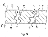
- each gas-permeable wall 7 comprises micropores (gas passage channels) 10 which put the inlet channels 6' of the exhaust gases in communication with the adjacent outlet channels 6" of the exhaust gases so that the exhaust gases flow through the micropores 10 as is better shown by the arrows in such a figure.
- the particulate material is thus trapped and essentially deposited on the surfaces of the gas-permeable walls 7 of the inlet channels 6' and on the walls of the micropores 10.
- the gas-permeable walls 7 and the micropores 10 are coated with at least one layer 11 of a catalytic composition to promote the combustion of the trapped particulate material and, therefore, to promote the passive regeneration of the filter 1 itself already at temperatures compatible with use of a vehicle even in an urban circulation, for example 250-300°C.
- the oxidizing device 1 can be an oxidizing device of the DOC type comprising a body 5', for example of the monolithic type, made of a substrate consisting of a material of the metallic 5'a or ceramic 5'b type as illustrated in figures 5a and 5b .
- the body 5' of the oxidizing device 1 has a substantially honeycomb structure comprising a plurality of open gas channels 6"', adjacent and parallel, delimited by walls 7 of said substrate.
- the body 5' of the oxidizing device 1 has a structure such that said channels are open on opposite sides of the body 5' at both the ends upstream 6a and downstream 6b of said body 5' with respect to a flowing direction of the exhaust gas.
- the post-treatment system 3 can comprise an oxidizing device (DOC) 5' and a particulate filter (DPF) 5, as defined above, combined in sequence in a system of the CRTTM type (Continuously Regenerating Trap).
- DOC oxidizing device
- DPF particulate filter
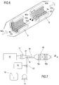
- the post-treatment system 3 comprises an oxidizing device (DOC or CRTTM) 17 a mixing section 18 and an SCR device 19 which allows to obtain an exhaust gas 20 with a low NO x content.
- DOC oxidizing device
- CRTTM oxidizing device
- the mixing section 18 comprises a dispensing device 14, for example comprising one or more nozzles, to inject a suitable reducing compound, for example urea taken from a tank 12 through a pump 13, in a conduit 21 for the passage of the exhaust gases coming from an internal combustion engine 16, for example a diesel engine.
- a suitable reducing compound for example urea taken from a tank 12 through a pump 13, in a conduit 21 for the passage of the exhaust gases coming from an internal combustion engine 16, for example a diesel engine.
- the flow rate of the urea injected by the dispensing device 14 is preferably regulated through a control unit 15 that controls an adjustment valve 22 according to the operating parameters of the engine 16.
- the mixing section 18 allows to mix the urea sprayed by the dispensing device 14 with the exhaust gas and preferably comprises a suitable static mixer, for example a metallic net, a metallic sponge, metal foils or other devices that allow to promote a close contact between the liquid phase (urea) and the gaseous phase (exhaust gas) and/or to create turbulence that promotes mixing.
- a suitable static mixer for example a metallic net, a metallic sponge, metal foils or other devices that allow to promote a close contact between the liquid phase (urea) and the gaseous phase (exhaust gas) and/or to create turbulence that promotes mixing.
- the SCR device 19 comprises a first hydrolysis section 19a that decomposes the urea to ammonia according to the following reaction: CO(NH 2 ) 2 + H 2 O ⁇ 2NH 3 + CO 2 and a second oxidation section 19b, in the presence of a catalyst, in which the ammonia reacts with the NO x forming N 2 and H 2 O according to the following chemical reactions: NO + NO 2 + 2NH 3 ⁇ 2N 2 + 3H 2 O 4NO + 4NH 3 + O 2 ⁇ 4N 2 + 6H 2 O 6NO 2 + 8NH 3 ⁇ 7N 2 + 12H 2 O 4NH 3 + 3O 2 ⁇ 2N 2 + 6H 2 O
- the surface area is measured through the BET technique using an ASAP 2010 analyser from Micromeritics.
- a first catalyst obtained by a preparation process according to the invention was prepared as follows.
- a second catalyst obtained by a preparation process according to the invention was prepared as follows.
- a third catalyst obtained by a preparation process according to the invention was prepared as follows.
- the crucible covered by a mesh was then placed in a pre-heated oven at 670 °C, for 20 minutes after having lowered the temperature to 650 °C.
- a fourth catalyst obtained by a preparation process according to the invention was prepared as follows.
- the crucible covered by a mesh was then placed in a pre-heated oven at 670 °C, for 20 minutes after having lowered the temperature to 650 °C.
- a fifth catalyst obtained by a preparation process according to the invention was prepared as follows.
- the crucible covered by a mesh was then placed in a pre-heated oven at 530 °C, for 20 minutes after having lowered the temperature to 500 °C.
- a sixth catalyst obtained by a preparation process according to the invention was prepared as follows.
- the crucible covered by a mesh was then placed in a pre-heated oven at 530 °C, for 20 minutes after having lowered the temperature to 500 °C.
- the Applicant has observed that the catalyst sample obtained by a preparation process according to the invention (Example 6) both fresh and after ageing has a sponge-like structure formed by single nanoparticles linked together, resulting in a random arrangement of holes and cavities.
- the holes have a roundish shape and most are merged together forming bigger holes with an irregular shape ( Phil. Trans. R. Soc.
- a commercial Mn 2 O 3 catalyst from Aldrich ( CAS 1317-34-6 ) with a surface area equal to 0.5 m 2 /g and two comparative Pt catalysts and the catalysts obtained by a preparation process according to the invention of examples 1, 3 and 6, prepared as described above, were subjected to analysis of the emitted gases in programmed oxidation conditions (TPO-EGA) in order to verify their catalytic efficiency in an oxidizing device of the DPF type. More specifically, these analyses were carried out according to the following experimental protocol.
- TPO-EGA programmed oxidation conditions
- particulate filter For the evaluation of the post-treatment system as particulate filter (DPF), an oven was used equipped with a temperature ramp equal to 5°C/min, starting from room temperature equal to 25°C up to a temperature equal to 600°C.
- the sample was prepared in a ball mill by mixing particulate material of the artificial type (Printex U, Degussa) and the catalyst according to a 1:9 weight ratio. The mixture was then under stirring for about 20 minutes. Then 50 mg of the powder thus obtained was taken and 250 mg of silica were added to this, so as to avoid the packing together of the catalytic bed subjected to the stream.
- the catalytic bed thus obtained was placed inside a U-shaped quartz tube between two layers of quartz wool, to avoid the powder being pulled by the gaseous flow to which the sample is subjected.
- the analysis of the gases emitted was carried out by chemiluminescence (EcoPhysics analyser) and NDIR (Non-Dispersive-Infrared Detection, ABB analyser).
- the CO 2 peak corresponds to the maximum speed of the combustion reaction observed in the experimental conditions so that the corresponding peak temperature can in turn be linked with the catalytic efficiency of the specific material analysed.
- Table 1 shows the data of the measurements carried out using three catalysts obtained by a preparation process according to the invention and a comparative commercial Mn 2 O 3 catalyst from Aldrich (CAS 1317-34-6). Table 1 also shows as comparative terms the data detected by mixing 12.6 mg of particles of particulate material (Printex® U) with 1.4 mg of Pt/Al 2 O 3 catalyst (1% and 5% by weight) (Sigma Aldrich).
- an oven was used equipped with a temperature ramp equal to 5°C/min, starting from room temperature equal to 25°C up to a temperature equal to 600°C.
- the sample was prepared by mixing 50 mg of the catalyst with 250 mg of silica, so as to avoid the packing together of the catalytic bed subjected to the stream.
- the catalytic bed thus obtained was placed inside a U-shaped quartz tube between two layers of quartz wool, to avoid the powder being pulled by the gaseous flow to which the sample is subjected.
- the analysis of the gases emitted was carried out by chemiluminescence (EcoPhysics analyser) and NDIR (Non-Dispersive-Infrared Detection, ABB analyser).
- the aged comparative catalysts and those obtained by a preparation process according to the invention were tested with the same protocol followed by the ageing process given above.
- Tables 2-3 show the data of the measurements carried out using two catalysts obtained by a preparation process according to the invention and a comparative Mn 2 O 3 catalyst from Aldrich (CAS 1317-34-6). Tables 2-3 also give as comparative terms the data detected with a Pt/Al 2 O 3 catalyst (1% by weight) (Sigma Aldrich).
- TABLE 2 Evaluation of the catalytic activity for oxidizing devices DOC by TPO-EGA analyses) Catalyst THC (100% conv) TCO (100% conv) THC (100% conv) TCO (100% conv) Fresh cat. Fresh cat. Aged cat. Aged cat.
- the advantages of the use of the catalysts obtained by the preparation process according to the invention with respect to the use of a Pt catalyst, as well as with respect to the use of a commercial manganese oxide, are evident. More particularly, the catalysts obtained by the preparation process of the present invention have a low cost and low environmental impact with respect to Pt. Moreover, the aforementioned Tables show that the catalysts obtained by the preparation process of the invention have higher activity in the combustion of the particulate material (Table 1), as well as higher activity (lower temperatures) in the total conversion of HC with respect to Pt and to commercial manganese oxide from Aldrich (Table 2). Moreover, from Table 2 a total CO conversion of the catalysts obtained by the preparation process of the invention at lower temperatures with respect to the manganese oxide of Aldrich is evident.
- Table 3 shows a higher activity in the NO conversion, after ageing, of the catalysts obtained by the preparation process according to the invention with respect to the Pt catalyst and a higher activity of the catalysts obtained by the preparation process of the present invention, when fresh, with respect to the commercial manganese oxide of Aldrich.
- the post-treatment system and the catalysts obtained by the preparation process of the present invention having a surface area equal to or greater than 10 m 2 /g for the fresh catalyst and smaller than the surface area of fresh catalyst and equal to or greater than 2 m 2 /g for the catalyst after ageing, allow to substantially improve the efficiency of the removal operations of the pollutants (CO, HC, NO x and PM) with respect to what is made possible by the catalysts of the prior art described above.
- This effect was particularly marked even after ageing despite a marked reduction in surface area of the catalyst.
- TPO-EGA programmed oxidation conditions
Landscapes
- Chemical & Material Sciences (AREA)
- Engineering & Computer Science (AREA)
- Chemical Kinetics & Catalysis (AREA)
- Organic Chemistry (AREA)
- Materials Engineering (AREA)
- Environmental & Geological Engineering (AREA)
- Analytical Chemistry (AREA)
- Biomedical Technology (AREA)
- Health & Medical Sciences (AREA)
- General Chemical & Material Sciences (AREA)
- Oil, Petroleum & Natural Gas (AREA)
- Physics & Mathematics (AREA)
- Thermal Sciences (AREA)
- Combustion & Propulsion (AREA)
- Inorganic Chemistry (AREA)
- Catalysts (AREA)
- Exhaust Gas After Treatment (AREA)
- Exhaust Gas Treatment By Means Of Catalyst (AREA)
Claims (4)
- Verfahren zur Herstellung eines Oxidationskatalysators, der im Wesentlichen aus einer katalytisch wirksamen Menge von Mn2O3 besteht, zur Reduzierung von Schadstoffen, die in einem Abgas vorhanden sind, wobei das Verfahren umfasst:a) Herstellen durch Mischen einer wässrigen Lösung umfassend eine Aminosäure und/oder Harnstoff und/oder Ammoniumnitrat und ein Mangansalz;b) Wärmebehandeln der so erhaltenen wässrigen Lösung in einem vorgeheizten Ofen bei einer Temperatur, die zwischen 500 °C und 650 °C liegt, für eine Zeitperiode zwischen 10 Minuten und 1 Stunde, um einen Katalysator zu erhalten, der aufweist:i) eine Oberfläche gleich oder größer als 10 m2/g in einem Zustand nach der Synthese und vor seiner ersten Verwendung, undii) eine Oberfläche nach Alterung kleiner als die Oberfläche des Katalysators unter den Bedingungen der Synthese und vor seiner ersten Verwendung, und gleich oder größer als 2 m2/g, wobei die Alterung erfolgt durch:- Platzieren einer Menge gleich 2 g des Katalysators unter den Bedingungen nach der Synthese vor seiner ersten Verwendung in einen statischen Luftofen;- Erhitzen der Menge des Katalysators mit einer Aufheizrate von 10 °C/min auf eine Alterungstemperatur von 800 °C;- Halten der Menge des Katalysators auf der Alterungstemperatur für eine Zeitperiode von 12 Stunden;
und- Entfernen der Probe aus dem Ofen am Ende des Halteschritts. - Verfahren nach Anspruch 1, wobei die Aminosäure Glycin ist und das Mangansalz Mangannitrat ist.
- Verfahren zur Herstellung eines Nachbehandlungssystems, umfassend:a) Bereitstellen eines Körpers, der aus einem Substrat besteht und mit einer Vielzahl von Gaskanälen versehen ist, die in dem Körper definiert sind und durch Wände aus dem Substrat begrenzt werden;b) Bereitstellen einer wässrigen Lösung umfassend eine Aminosäure und/oder Harnstoff und/oder Ammoniumnitrat und ein Mangansalz;c) Imprägnieren des Substrats des Körpers mit der wässrigen Lösung;d) Wärmebehandeln der so erhaltenen wässrigen Lösung in einem vorgeheizten Ofen bei einer Temperatur, die zwischen 500 °C und 650 °C liegt, für eine Zeitperiode zwischen 10 Minuten und 1 Stunde, um die Substratwände mit einem Katalysator in Form von festen Partikeln aus Mn2O3 zu beschichten; wobei der Katalysator aufweist:i) eine Oberfläche gleich oder größer als 10 m2/g unter den Bedingungen nach der Synthese und vor seiner ersten Verwendung, undii) eine Oberfläche nach Alterung kleiner als die Oberfläche des Katalysators unter den Bedingungen der Synthese und vor seiner ersten Verwendung, und gleich oder größer als 2 m2/g, wobei die Alterung erfolgt durch:- Platzieren einer Menge gleich 2 g des Katalysators unter den Bedingungen nach der Synthese vor seiner ersten Verwendung in einen statischen Luftofen;- Erhitzen der Menge des Katalysators mit einer Aufheizrate von 10 °C/min auf eine Alterungstemperatur von 800 °C;- Halten der Menge des Katalysators auf der Alterungstemperatur für eine Zeitperiode von 12 Stunden;
und- Entfernen der Probe aus dem Ofen am Ende des Halteschritts. - Verfahren nach Anspruch 3, wobei die Aminosäure Glycin ist und das Mangansalz Mangannitrat ist.
Applications Claiming Priority (3)
| Application Number | Priority Date | Filing Date | Title |
|---|---|---|---|
| ITMI20111780 | 2011-09-30 | ||
| US201161581284P | 2011-12-29 | 2011-12-29 | |
| PCT/IB2012/055160 WO2013046150A1 (en) | 2011-09-30 | 2012-09-27 | Post-treatment system of an exhaust gas, catalyst useful for said system and processes for their preparation |
Publications (2)
| Publication Number | Publication Date |
|---|---|
| EP2747878A1 EP2747878A1 (de) | 2014-07-02 |
| EP2747878B1 true EP2747878B1 (de) | 2019-04-10 |
Family
ID=45034059
Family Applications (1)
| Application Number | Title | Priority Date | Filing Date |
|---|---|---|---|
| EP12780855.8A Active EP2747878B1 (de) | 2011-09-30 | 2012-09-27 | Verfahren zur herstellung eines oxidationskatalysators und eines abgasnachbehandlungssystems |
Country Status (4)
| Country | Link |
|---|---|
| EP (1) | EP2747878B1 (de) |
| CN (1) | CN103958033B (de) |
| BR (1) | BR112014007153A2 (de) |
| WO (1) | WO2013046150A1 (de) |
Families Citing this family (6)
| Publication number | Priority date | Publication date | Assignee | Title |
|---|---|---|---|---|
| US10864502B2 (en) | 2013-12-16 | 2020-12-15 | Basf Corporation | Manganese-containing diesel oxidation catalyst |
| US10335776B2 (en) | 2013-12-16 | 2019-07-02 | Basf Corporation | Manganese-containing diesel oxidation catalyst |
| JP7057691B2 (ja) * | 2018-03-19 | 2022-04-20 | 日本碍子株式会社 | ハニカム構造体 |
| US10646824B2 (en) | 2018-06-12 | 2020-05-12 | Mainsteam Engineering Corporation | Catalytic cookstove with passive control of draft and method of use |
| BR112021013873A2 (pt) * | 2019-01-18 | 2021-09-14 | Cummins Emission Solutions Inc. | Catalisadores de rcs tratados com resistência ao enxofre melhorada |
| US12544739B2 (en) * | 2022-05-27 | 2026-02-10 | Johnson Matthey Public Limited Company | Method for manufacturing gasoline particulate filter |
Family Cites Families (11)
| Publication number | Priority date | Publication date | Assignee | Title |
|---|---|---|---|---|
| US4902487A (en) | 1988-05-13 | 1990-02-20 | Johnson Matthey, Inc. | Treatment of diesel exhaust gases |
| GB9802504D0 (en) | 1998-02-06 | 1998-04-01 | Johnson Matthey Plc | Improvements in emission control |
| EP1378288A3 (de) | 2002-04-18 | 2004-01-14 | Ford Global Technologies, LLC, A subsidary of Ford Motor Company | Platingruppenmetal-freie katalytische Beschichtung für Abgas-Partikelfilter |
| JP2004230223A (ja) | 2003-01-28 | 2004-08-19 | Fujitsu Ltd | Co酸化触媒およびその製造方法 |
| CN1954137B (zh) * | 2005-07-21 | 2011-12-21 | 揖斐电株式会社 | 蜂窝结构体以及废气净化装置 |
| JP4835193B2 (ja) | 2006-02-20 | 2011-12-14 | マツダ株式会社 | ディーゼルパティキュレートフィルタ |
| US7767175B2 (en) * | 2007-01-09 | 2010-08-03 | Catalytic Solutions, Inc. | Ammonia SCR catalyst and method of using the catalyst |
| WO2008129670A1 (ja) * | 2007-04-17 | 2008-10-30 | Ibiden Co., Ltd. | 触媒担持ハニカムおよびその製造方法 |
| JP2009125688A (ja) | 2007-11-26 | 2009-06-11 | F C C:Kk | 触媒の製造方法 |
| RU2570454C2 (ru) * | 2010-02-01 | 2015-12-10 | Джонсон Мэтти Плс | Экструдированный scr-фильтр |
| CN101979140A (zh) * | 2010-10-19 | 2011-02-23 | 大连理工大学 | 一种选择性催化氧化氨气的金属负载型催化剂、制备方法及其应用 |
-
2012
- 2012-09-27 WO PCT/IB2012/055160 patent/WO2013046150A1/en not_active Ceased
- 2012-09-27 CN CN201280054796.8A patent/CN103958033B/zh active Active
- 2012-09-27 EP EP12780855.8A patent/EP2747878B1/de active Active
- 2012-09-27 BR BR112014007153A patent/BR112014007153A2/pt not_active IP Right Cessation
Non-Patent Citations (1)
| Title |
|---|
| None * |
Also Published As
| Publication number | Publication date |
|---|---|
| CN103958033B (zh) | 2016-06-15 |
| BR112014007153A2 (pt) | 2017-04-11 |
| EP2747878A1 (de) | 2014-07-02 |
| WO2013046150A1 (en) | 2013-04-04 |
| CN103958033A (zh) | 2014-07-30 |
Similar Documents
| Publication | Publication Date | Title |
|---|---|---|
| EP3004578B1 (de) | Katalysierter filter zur abgasbehandlung | |
| US8883100B2 (en) | Particle reduction with combined SCR and NH3 slip catalyst | |
| CN107262108B (zh) | 含有过渡金属氧化物的二氧化铈粒子 | |
| JP6416098B2 (ja) | 触媒化煤フィルタ | |
| US9687786B2 (en) | Catalyzed filter for treating exhaust gas | |
| US20110258994A1 (en) | Bifunctional Catalyst for Decomposition and Oxidation of Nitrogen Monoxide, Composite Catalyst Including the Same for Apparatus to Decrease Exhaust Gas, and Method for Preparation Thereof | |
| JP2011509826A (ja) | 触媒フィルタ | |
| CN102597447A (zh) | 四效柴油催化剂和使用方法 | |
| EP2747878B1 (de) | Verfahren zur herstellung eines oxidationskatalysators und eines abgasnachbehandlungssystems | |
| JP2012528705A (ja) | Scr触媒を含むパーシャルフィルタ基板及び排出処理システム及びエンジンの排気処理方法 | |
| AU2015221463B2 (en) | Urea hydrolysis reactor for selective catalytic reduction | |
| RU2754996C2 (ru) | КАТАЛИЗАТОР-АДСОРБЕР NOx | |
| GB2562870A (en) | NOx adsorber catalyst | |
| CN102292152A (zh) | 具有良好低温活性的柴油机氧化催化剂 | |
| GB2562609A (en) | NOx Adsorber catalyst | |
| JP7076241B2 (ja) | 酸化触媒の粉末、触媒担持構造体、酸化触媒の粉末の製造方法、および、触媒担持構造体の製造方法 | |
| JP2006289211A (ja) | アンモニア酸化触媒 | |
| WO2025252796A1 (en) | Mn-perovskite catalyst for the treatment of an exhaust gas stream containing one or more of formaldehyde, nitrogen oxide (no), and hydrocarbons | |
| CN120418002A (zh) | 用于选择性催化还原的金属氧化物催化剂 | |
| CN121100220A (zh) | 用于处理废气的系统 |
Legal Events
| Date | Code | Title | Description |
|---|---|---|---|
| PUAI | Public reference made under article 153(3) epc to a published international application that has entered the european phase |
Free format text: ORIGINAL CODE: 0009012 |
|
| 17P | Request for examination filed |
Effective date: 20140319 |
|
| AK | Designated contracting states |
Kind code of ref document: A1 Designated state(s): AL AT BE BG CH CY CZ DE DK EE ES FI FR GB GR HR HU IE IS IT LI LT LU LV MC MK MT NL NO PL PT RO RS SE SI SK SM TR |
|
| DAX | Request for extension of the european patent (deleted) | ||
| STAA | Information on the status of an ep patent application or granted ep patent |
Free format text: STATUS: EXAMINATION IS IN PROGRESS |
|
| 17Q | First examination report despatched |
Effective date: 20170714 |
|
| GRAP | Despatch of communication of intention to grant a patent |
Free format text: ORIGINAL CODE: EPIDOSNIGR1 |
|
| STAA | Information on the status of an ep patent application or granted ep patent |
Free format text: STATUS: GRANT OF PATENT IS INTENDED |
|
| RAP1 | Party data changed (applicant data changed or rights of an application transferred) |
Owner name: PIRELLI TYRE S.P.A. |
|
| INTG | Intention to grant announced |
Effective date: 20181031 |
|
| GRAS | Grant fee paid |
Free format text: ORIGINAL CODE: EPIDOSNIGR3 |
|
| GRAA | (expected) grant |
Free format text: ORIGINAL CODE: 0009210 |
|
| STAA | Information on the status of an ep patent application or granted ep patent |
Free format text: STATUS: THE PATENT HAS BEEN GRANTED |
|
| RIN1 | Information on inventor provided before grant (corrected) |
Inventor name: RUSSO, NUNZIO Inventor name: AMBROSINI, TIZIANO Inventor name: FINO, DEBORA Inventor name: SIN XICOLA, AGUSTIN |
|
| AK | Designated contracting states |
Kind code of ref document: B1 Designated state(s): AL AT BE BG CH CY CZ DE DK EE ES FI FR GB GR HR HU IE IS IT LI LT LU LV MC MK MT NL NO PL PT RO RS SE SI SK SM TR |
|
| REG | Reference to a national code |
Ref country code: GB Ref legal event code: FG4D |
|
| REG | Reference to a national code |
Ref country code: CH Ref legal event code: EP Ref country code: AT Ref legal event code: REF Ref document number: 1117926 Country of ref document: AT Kind code of ref document: T Effective date: 20190415 |
|
| REG | Reference to a national code |
Ref country code: IE Ref legal event code: FG4D |
|
| REG | Reference to a national code |
Ref country code: DE Ref legal event code: R096 Ref document number: 602012058878 Country of ref document: DE |
|
| REG | Reference to a national code |
Ref country code: NL Ref legal event code: MP Effective date: 20190410 |
|
| REG | Reference to a national code |
Ref country code: LT Ref legal event code: MG4D |
|
| REG | Reference to a national code |
Ref country code: AT Ref legal event code: MK05 Ref document number: 1117926 Country of ref document: AT Kind code of ref document: T Effective date: 20190410 |
|
| PG25 | Lapsed in a contracting state [announced via postgrant information from national office to epo] |
Ref country code: NL Free format text: LAPSE BECAUSE OF FAILURE TO SUBMIT A TRANSLATION OF THE DESCRIPTION OR TO PAY THE FEE WITHIN THE PRESCRIBED TIME-LIMIT Effective date: 20190410 |
|
| PG25 | Lapsed in a contracting state [announced via postgrant information from national office to epo] |
Ref country code: HR Free format text: LAPSE BECAUSE OF FAILURE TO SUBMIT A TRANSLATION OF THE DESCRIPTION OR TO PAY THE FEE WITHIN THE PRESCRIBED TIME-LIMIT Effective date: 20190410 Ref country code: LT Free format text: LAPSE BECAUSE OF FAILURE TO SUBMIT A TRANSLATION OF THE DESCRIPTION OR TO PAY THE FEE WITHIN THE PRESCRIBED TIME-LIMIT Effective date: 20190410 Ref country code: AL Free format text: LAPSE BECAUSE OF FAILURE TO SUBMIT A TRANSLATION OF THE DESCRIPTION OR TO PAY THE FEE WITHIN THE PRESCRIBED TIME-LIMIT Effective date: 20190410 Ref country code: FI Free format text: LAPSE BECAUSE OF FAILURE TO SUBMIT A TRANSLATION OF THE DESCRIPTION OR TO PAY THE FEE WITHIN THE PRESCRIBED TIME-LIMIT Effective date: 20190410 Ref country code: NO Free format text: LAPSE BECAUSE OF FAILURE TO SUBMIT A TRANSLATION OF THE DESCRIPTION OR TO PAY THE FEE WITHIN THE PRESCRIBED TIME-LIMIT Effective date: 20190710 Ref country code: PT Free format text: LAPSE BECAUSE OF FAILURE TO SUBMIT A TRANSLATION OF THE DESCRIPTION OR TO PAY THE FEE WITHIN THE PRESCRIBED TIME-LIMIT Effective date: 20190910 Ref country code: SE Free format text: LAPSE BECAUSE OF FAILURE TO SUBMIT A TRANSLATION OF THE DESCRIPTION OR TO PAY THE FEE WITHIN THE PRESCRIBED TIME-LIMIT Effective date: 20190410 Ref country code: ES Free format text: LAPSE BECAUSE OF FAILURE TO SUBMIT A TRANSLATION OF THE DESCRIPTION OR TO PAY THE FEE WITHIN THE PRESCRIBED TIME-LIMIT Effective date: 20190410 |
|
| PG25 | Lapsed in a contracting state [announced via postgrant information from national office to epo] |
Ref country code: GR Free format text: LAPSE BECAUSE OF FAILURE TO SUBMIT A TRANSLATION OF THE DESCRIPTION OR TO PAY THE FEE WITHIN THE PRESCRIBED TIME-LIMIT Effective date: 20190711 Ref country code: RS Free format text: LAPSE BECAUSE OF FAILURE TO SUBMIT A TRANSLATION OF THE DESCRIPTION OR TO PAY THE FEE WITHIN THE PRESCRIBED TIME-LIMIT Effective date: 20190410 Ref country code: BG Free format text: LAPSE BECAUSE OF FAILURE TO SUBMIT A TRANSLATION OF THE DESCRIPTION OR TO PAY THE FEE WITHIN THE PRESCRIBED TIME-LIMIT Effective date: 20190710 Ref country code: LV Free format text: LAPSE BECAUSE OF FAILURE TO SUBMIT A TRANSLATION OF THE DESCRIPTION OR TO PAY THE FEE WITHIN THE PRESCRIBED TIME-LIMIT Effective date: 20190410 Ref country code: PL Free format text: LAPSE BECAUSE OF FAILURE TO SUBMIT A TRANSLATION OF THE DESCRIPTION OR TO PAY THE FEE WITHIN THE PRESCRIBED TIME-LIMIT Effective date: 20190410 |
|
| PG25 | Lapsed in a contracting state [announced via postgrant information from national office to epo] |
Ref country code: IS Free format text: LAPSE BECAUSE OF FAILURE TO SUBMIT A TRANSLATION OF THE DESCRIPTION OR TO PAY THE FEE WITHIN THE PRESCRIBED TIME-LIMIT Effective date: 20190810 Ref country code: AT Free format text: LAPSE BECAUSE OF FAILURE TO SUBMIT A TRANSLATION OF THE DESCRIPTION OR TO PAY THE FEE WITHIN THE PRESCRIBED TIME-LIMIT Effective date: 20190410 |
|
| REG | Reference to a national code |
Ref country code: DE Ref legal event code: R097 Ref document number: 602012058878 Country of ref document: DE |
|
| PG25 | Lapsed in a contracting state [announced via postgrant information from national office to epo] |
Ref country code: EE Free format text: LAPSE BECAUSE OF FAILURE TO SUBMIT A TRANSLATION OF THE DESCRIPTION OR TO PAY THE FEE WITHIN THE PRESCRIBED TIME-LIMIT Effective date: 20190410 Ref country code: SK Free format text: LAPSE BECAUSE OF FAILURE TO SUBMIT A TRANSLATION OF THE DESCRIPTION OR TO PAY THE FEE WITHIN THE PRESCRIBED TIME-LIMIT Effective date: 20190410 Ref country code: DK Free format text: LAPSE BECAUSE OF FAILURE TO SUBMIT A TRANSLATION OF THE DESCRIPTION OR TO PAY THE FEE WITHIN THE PRESCRIBED TIME-LIMIT Effective date: 20190410 Ref country code: CZ Free format text: LAPSE BECAUSE OF FAILURE TO SUBMIT A TRANSLATION OF THE DESCRIPTION OR TO PAY THE FEE WITHIN THE PRESCRIBED TIME-LIMIT Effective date: 20190410 Ref country code: RO Free format text: LAPSE BECAUSE OF FAILURE TO SUBMIT A TRANSLATION OF THE DESCRIPTION OR TO PAY THE FEE WITHIN THE PRESCRIBED TIME-LIMIT Effective date: 20190410 |
|
| PLBE | No opposition filed within time limit |
Free format text: ORIGINAL CODE: 0009261 |
|
| STAA | Information on the status of an ep patent application or granted ep patent |
Free format text: STATUS: NO OPPOSITION FILED WITHIN TIME LIMIT |
|
| PG25 | Lapsed in a contracting state [announced via postgrant information from national office to epo] |
Ref country code: SM Free format text: LAPSE BECAUSE OF FAILURE TO SUBMIT A TRANSLATION OF THE DESCRIPTION OR TO PAY THE FEE WITHIN THE PRESCRIBED TIME-LIMIT Effective date: 20190410 |
|
| 26N | No opposition filed |
Effective date: 20200113 |
|
| PG25 | Lapsed in a contracting state [announced via postgrant information from national office to epo] |
Ref country code: TR Free format text: LAPSE BECAUSE OF FAILURE TO SUBMIT A TRANSLATION OF THE DESCRIPTION OR TO PAY THE FEE WITHIN THE PRESCRIBED TIME-LIMIT Effective date: 20190410 |
|
| PG25 | Lapsed in a contracting state [announced via postgrant information from national office to epo] |
Ref country code: SI Free format text: LAPSE BECAUSE OF FAILURE TO SUBMIT A TRANSLATION OF THE DESCRIPTION OR TO PAY THE FEE WITHIN THE PRESCRIBED TIME-LIMIT Effective date: 20190410 Ref country code: MC Free format text: LAPSE BECAUSE OF FAILURE TO SUBMIT A TRANSLATION OF THE DESCRIPTION OR TO PAY THE FEE WITHIN THE PRESCRIBED TIME-LIMIT Effective date: 20190410 |
|
| REG | Reference to a national code |
Ref country code: CH Ref legal event code: PL |
|
| PG25 | Lapsed in a contracting state [announced via postgrant information from national office to epo] |
Ref country code: LI Free format text: LAPSE BECAUSE OF NON-PAYMENT OF DUE FEES Effective date: 20190930 Ref country code: CH Free format text: LAPSE BECAUSE OF NON-PAYMENT OF DUE FEES Effective date: 20190930 Ref country code: LU Free format text: LAPSE BECAUSE OF NON-PAYMENT OF DUE FEES Effective date: 20190927 Ref country code: IE Free format text: LAPSE BECAUSE OF NON-PAYMENT OF DUE FEES Effective date: 20190927 |
|
| REG | Reference to a national code |
Ref country code: BE Ref legal event code: MM Effective date: 20190930 |
|
| PG25 | Lapsed in a contracting state [announced via postgrant information from national office to epo] |
Ref country code: BE Free format text: LAPSE BECAUSE OF NON-PAYMENT OF DUE FEES Effective date: 20190930 |
|
| GBPC | Gb: european patent ceased through non-payment of renewal fee |
Effective date: 20190927 |
|
| PG25 | Lapsed in a contracting state [announced via postgrant information from national office to epo] |
Ref country code: FR Free format text: LAPSE BECAUSE OF NON-PAYMENT OF DUE FEES Effective date: 20190930 Ref country code: GB Free format text: LAPSE BECAUSE OF NON-PAYMENT OF DUE FEES Effective date: 20190927 |
|
| PG25 | Lapsed in a contracting state [announced via postgrant information from national office to epo] |
Ref country code: CY Free format text: LAPSE BECAUSE OF FAILURE TO SUBMIT A TRANSLATION OF THE DESCRIPTION OR TO PAY THE FEE WITHIN THE PRESCRIBED TIME-LIMIT Effective date: 20190410 |
|
| PG25 | Lapsed in a contracting state [announced via postgrant information from national office to epo] |
Ref country code: HU Free format text: LAPSE BECAUSE OF FAILURE TO SUBMIT A TRANSLATION OF THE DESCRIPTION OR TO PAY THE FEE WITHIN THE PRESCRIBED TIME-LIMIT; INVALID AB INITIO Effective date: 20120927 Ref country code: MT Free format text: LAPSE BECAUSE OF FAILURE TO SUBMIT A TRANSLATION OF THE DESCRIPTION OR TO PAY THE FEE WITHIN THE PRESCRIBED TIME-LIMIT Effective date: 20190410 |
|
| PG25 | Lapsed in a contracting state [announced via postgrant information from national office to epo] |
Ref country code: MK Free format text: LAPSE BECAUSE OF FAILURE TO SUBMIT A TRANSLATION OF THE DESCRIPTION OR TO PAY THE FEE WITHIN THE PRESCRIBED TIME-LIMIT Effective date: 20190410 |
|
| PGFP | Annual fee paid to national office [announced via postgrant information from national office to epo] |
Ref country code: DE Payment date: 20250929 Year of fee payment: 14 |
|
| PGFP | Annual fee paid to national office [announced via postgrant information from national office to epo] |
Ref country code: IT Payment date: 20250919 Year of fee payment: 14 |