EP2747984B1 - Verfahren und vorrichtung zum laserschweissen von zwei fügepartnern aus kunststoff - Google Patents
Verfahren und vorrichtung zum laserschweissen von zwei fügepartnern aus kunststoff Download PDFInfo
- Publication number
- EP2747984B1 EP2747984B1 EP12753681.1A EP12753681A EP2747984B1 EP 2747984 B1 EP2747984 B1 EP 2747984B1 EP 12753681 A EP12753681 A EP 12753681A EP 2747984 B1 EP2747984 B1 EP 2747984B1
- Authority
- EP
- European Patent Office
- Prior art keywords
- laser beam
- seam
- laser
- modulation
- welding
- Prior art date
- Legal status (The legal status is an assumption and is not a legal conclusion. Google has not performed a legal analysis and makes no representation as to the accuracy of the status listed.)
- Not-in-force
Links
Images


Classifications
-
- B—PERFORMING OPERATIONS; TRANSPORTING
- B29—WORKING OF PLASTICS; WORKING OF SUBSTANCES IN A PLASTIC STATE IN GENERAL
- B29C—SHAPING OR JOINING OF PLASTICS; SHAPING OF MATERIAL IN A PLASTIC STATE, NOT OTHERWISE PROVIDED FOR; AFTER-TREATMENT OF THE SHAPED PRODUCTS, e.g. REPAIRING
- B29C65/00—Joining or sealing of preformed parts, e.g. welding of plastics materials; Apparatus therefor
- B29C65/02—Joining or sealing of preformed parts, e.g. welding of plastics materials; Apparatus therefor by heating, with or without pressure
- B29C65/14—Joining or sealing of preformed parts, e.g. welding of plastics materials; Apparatus therefor by heating, with or without pressure using wave energy, i.e. electromagnetic radiation, or particle radiation
- B29C65/16—Laser beams
- B29C65/1629—Laser beams characterised by the way of heating the interface
- B29C65/1635—Laser beams characterised by the way of heating the interface at least passing through one of the parts to be joined, i.e. laser transmission welding
- B29C65/1638—Laser beams characterised by the way of heating the interface at least passing through one of the parts to be joined, i.e. laser transmission welding focusing the laser beam on the interface
-
- B—PERFORMING OPERATIONS; TRANSPORTING
- B23—MACHINE TOOLS; METAL-WORKING NOT OTHERWISE PROVIDED FOR
- B23K—SOLDERING OR UNSOLDERING; WELDING; CLADDING OR PLATING BY SOLDERING OR WELDING; CUTTING BY APPLYING HEAT LOCALLY, e.g. FLAME CUTTING; WORKING BY LASER BEAM
- B23K26/00—Working by laser beam, e.g. welding, cutting or boring
- B23K26/02—Positioning or observing the workpiece, e.g. with respect to the point of impact; Aligning, aiming or focusing the laser beam
- B23K26/04—Automatically aligning, aiming or focusing the laser beam, e.g. using the back-scattered light
- B23K26/046—Automatically focusing the laser beam
-
- B—PERFORMING OPERATIONS; TRANSPORTING
- B23—MACHINE TOOLS; METAL-WORKING NOT OTHERWISE PROVIDED FOR
- B23K—SOLDERING OR UNSOLDERING; WELDING; CLADDING OR PLATING BY SOLDERING OR WELDING; CUTTING BY APPLYING HEAT LOCALLY, e.g. FLAME CUTTING; WORKING BY LASER BEAM
- B23K26/00—Working by laser beam, e.g. welding, cutting or boring
- B23K26/02—Positioning or observing the workpiece, e.g. with respect to the point of impact; Aligning, aiming or focusing the laser beam
- B23K26/06—Shaping the laser beam, e.g. by masks or multi-focusing
- B23K26/064—Shaping the laser beam, e.g. by masks or multi-focusing by means of optical elements, e.g. lenses, mirrors or prisms
- B23K26/0648—Shaping the laser beam, e.g. by masks or multi-focusing by means of optical elements, e.g. lenses, mirrors or prisms comprising lenses
-
- B—PERFORMING OPERATIONS; TRANSPORTING
- B23—MACHINE TOOLS; METAL-WORKING NOT OTHERWISE PROVIDED FOR
- B23K—SOLDERING OR UNSOLDERING; WELDING; CLADDING OR PLATING BY SOLDERING OR WELDING; CUTTING BY APPLYING HEAT LOCALLY, e.g. FLAME CUTTING; WORKING BY LASER BEAM
- B23K26/00—Working by laser beam, e.g. welding, cutting or boring
- B23K26/20—Bonding
- B23K26/32—Bonding taking account of the properties of the material involved
- B23K26/324—Bonding taking account of the properties of the material involved involving non-metallic parts
-
- B—PERFORMING OPERATIONS; TRANSPORTING
- B29—WORKING OF PLASTICS; WORKING OF SUBSTANCES IN A PLASTIC STATE IN GENERAL
- B29C—SHAPING OR JOINING OF PLASTICS; SHAPING OF MATERIAL IN A PLASTIC STATE, NOT OTHERWISE PROVIDED FOR; AFTER-TREATMENT OF THE SHAPED PRODUCTS, e.g. REPAIRING
- B29C65/00—Joining or sealing of preformed parts, e.g. welding of plastics materials; Apparatus therefor
- B29C65/02—Joining or sealing of preformed parts, e.g. welding of plastics materials; Apparatus therefor by heating, with or without pressure
- B29C65/14—Joining or sealing of preformed parts, e.g. welding of plastics materials; Apparatus therefor by heating, with or without pressure using wave energy, i.e. electromagnetic radiation, or particle radiation
- B29C65/16—Laser beams
- B29C65/1629—Laser beams characterised by the way of heating the interface
- B29C65/1635—Laser beams characterised by the way of heating the interface at least passing through one of the parts to be joined, i.e. laser transmission welding
-
- B—PERFORMING OPERATIONS; TRANSPORTING
- B29—WORKING OF PLASTICS; WORKING OF SUBSTANCES IN A PLASTIC STATE IN GENERAL
- B29C—SHAPING OR JOINING OF PLASTICS; SHAPING OF MATERIAL IN A PLASTIC STATE, NOT OTHERWISE PROVIDED FOR; AFTER-TREATMENT OF THE SHAPED PRODUCTS, e.g. REPAIRING
- B29C65/00—Joining or sealing of preformed parts, e.g. welding of plastics materials; Apparatus therefor
- B29C65/02—Joining or sealing of preformed parts, e.g. welding of plastics materials; Apparatus therefor by heating, with or without pressure
- B29C65/14—Joining or sealing of preformed parts, e.g. welding of plastics materials; Apparatus therefor by heating, with or without pressure using wave energy, i.e. electromagnetic radiation, or particle radiation
- B29C65/16—Laser beams
- B29C65/1629—Laser beams characterised by the way of heating the interface
- B29C65/1648—Laser beams characterised by the way of heating the interface radiating the edges of the parts to be joined
-
- B—PERFORMING OPERATIONS; TRANSPORTING
- B29—WORKING OF PLASTICS; WORKING OF SUBSTANCES IN A PLASTIC STATE IN GENERAL
- B29C—SHAPING OR JOINING OF PLASTICS; SHAPING OF MATERIAL IN A PLASTIC STATE, NOT OTHERWISE PROVIDED FOR; AFTER-TREATMENT OF THE SHAPED PRODUCTS, e.g. REPAIRING
- B29C65/00—Joining or sealing of preformed parts, e.g. welding of plastics materials; Apparatus therefor
- B29C65/02—Joining or sealing of preformed parts, e.g. welding of plastics materials; Apparatus therefor by heating, with or without pressure
- B29C65/14—Joining or sealing of preformed parts, e.g. welding of plastics materials; Apparatus therefor by heating, with or without pressure using wave energy, i.e. electromagnetic radiation, or particle radiation
- B29C65/16—Laser beams
- B29C65/1629—Laser beams characterised by the way of heating the interface
- B29C65/1654—Laser beams characterised by the way of heating the interface scanning at least one of the parts to be joined
- B29C65/1658—Laser beams characterised by the way of heating the interface scanning at least one of the parts to be joined scanning once, e.g. contour laser welding
-
- B—PERFORMING OPERATIONS; TRANSPORTING
- B29—WORKING OF PLASTICS; WORKING OF SUBSTANCES IN A PLASTIC STATE IN GENERAL
- B29C—SHAPING OR JOINING OF PLASTICS; SHAPING OF MATERIAL IN A PLASTIC STATE, NOT OTHERWISE PROVIDED FOR; AFTER-TREATMENT OF THE SHAPED PRODUCTS, e.g. REPAIRING
- B29C66/00—General aspects of processes or apparatus for joining preformed parts
- B29C66/01—General aspects dealing with the joint area or with the area to be joined
- B29C66/05—Particular design of joint configurations
- B29C66/10—Particular design of joint configurations particular design of the joint cross-sections
- B29C66/11—Joint cross-sections comprising a single joint-segment, i.e. one of the parts to be joined comprising a single joint-segment in the joint cross-section
- B29C66/112—Single lapped joints
- B29C66/1122—Single lap to lap joints, i.e. overlap joints
-
- B—PERFORMING OPERATIONS; TRANSPORTING
- B29—WORKING OF PLASTICS; WORKING OF SUBSTANCES IN A PLASTIC STATE IN GENERAL
- B29C—SHAPING OR JOINING OF PLASTICS; SHAPING OF MATERIAL IN A PLASTIC STATE, NOT OTHERWISE PROVIDED FOR; AFTER-TREATMENT OF THE SHAPED PRODUCTS, e.g. REPAIRING
- B29C66/00—General aspects of processes or apparatus for joining preformed parts
- B29C66/01—General aspects dealing with the joint area or with the area to be joined
- B29C66/05—Particular design of joint configurations
- B29C66/10—Particular design of joint configurations particular design of the joint cross-sections
- B29C66/11—Joint cross-sections comprising a single joint-segment, i.e. one of the parts to be joined comprising a single joint-segment in the joint cross-section
- B29C66/114—Single butt joints
- B29C66/1142—Single butt to butt joints
-
- B—PERFORMING OPERATIONS; TRANSPORTING
- B29—WORKING OF PLASTICS; WORKING OF SUBSTANCES IN A PLASTIC STATE IN GENERAL
- B29C—SHAPING OR JOINING OF PLASTICS; SHAPING OF MATERIAL IN A PLASTIC STATE, NOT OTHERWISE PROVIDED FOR; AFTER-TREATMENT OF THE SHAPED PRODUCTS, e.g. REPAIRING
- B29C66/00—General aspects of processes or apparatus for joining preformed parts
- B29C66/40—General aspects of joining substantially flat articles, e.g. plates, sheets or web-like materials; Making flat seams in tubular or hollow articles; Joining single elements to substantially flat surfaces
- B29C66/41—Joining substantially flat articles ; Making flat seams in tubular or hollow articles
- B29C66/43—Joining a relatively small portion of the surface of said articles
-
- B—PERFORMING OPERATIONS; TRANSPORTING
- B29—WORKING OF PLASTICS; WORKING OF SUBSTANCES IN A PLASTIC STATE IN GENERAL
- B29C—SHAPING OR JOINING OF PLASTICS; SHAPING OF MATERIAL IN A PLASTIC STATE, NOT OTHERWISE PROVIDED FOR; AFTER-TREATMENT OF THE SHAPED PRODUCTS, e.g. REPAIRING
- B29C66/00—General aspects of processes or apparatus for joining preformed parts
- B29C66/40—General aspects of joining substantially flat articles, e.g. plates, sheets or web-like materials; Making flat seams in tubular or hollow articles; Joining single elements to substantially flat surfaces
- B29C66/41—Joining substantially flat articles ; Making flat seams in tubular or hollow articles
- B29C66/45—Joining of substantially the whole surface of the articles
-
- B—PERFORMING OPERATIONS; TRANSPORTING
- B29—WORKING OF PLASTICS; WORKING OF SUBSTANCES IN A PLASTIC STATE IN GENERAL
- B29C—SHAPING OR JOINING OF PLASTICS; SHAPING OF MATERIAL IN A PLASTIC STATE, NOT OTHERWISE PROVIDED FOR; AFTER-TREATMENT OF THE SHAPED PRODUCTS, e.g. REPAIRING
- B29C66/00—General aspects of processes or apparatus for joining preformed parts
- B29C66/80—General aspects of machine operations or constructions and parts thereof
- B29C66/83—General aspects of machine operations or constructions and parts thereof characterised by the movement of the joining or pressing tools
- B29C66/836—Moving relative to and tangentially to the parts to be joined, e.g. transversely to the displacement of the parts to be joined, e.g. using a X-Y table
-
- B—PERFORMING OPERATIONS; TRANSPORTING
- B29—WORKING OF PLASTICS; WORKING OF SUBSTANCES IN A PLASTIC STATE IN GENERAL
- B29C—SHAPING OR JOINING OF PLASTICS; SHAPING OF MATERIAL IN A PLASTIC STATE, NOT OTHERWISE PROVIDED FOR; AFTER-TREATMENT OF THE SHAPED PRODUCTS, e.g. REPAIRING
- B29C66/00—General aspects of processes or apparatus for joining preformed parts
- B29C66/90—Measuring or controlling the joining process
- B29C66/91—Measuring or controlling the joining process by measuring or controlling the temperature, the heat or the thermal flux
- B29C66/914—Measuring or controlling the joining process by measuring or controlling the temperature, the heat or the thermal flux by controlling or regulating the temperature, the heat or the thermal flux
- B29C66/9161—Measuring or controlling the joining process by measuring or controlling the temperature, the heat or the thermal flux by controlling or regulating the temperature, the heat or the thermal flux by controlling or regulating the heat or the thermal flux, i.e. the heat flux
-
- B—PERFORMING OPERATIONS; TRANSPORTING
- B29—WORKING OF PLASTICS; WORKING OF SUBSTANCES IN A PLASTIC STATE IN GENERAL
- B29C—SHAPING OR JOINING OF PLASTICS; SHAPING OF MATERIAL IN A PLASTIC STATE, NOT OTHERWISE PROVIDED FOR; AFTER-TREATMENT OF THE SHAPED PRODUCTS, e.g. REPAIRING
- B29C66/00—General aspects of processes or apparatus for joining preformed parts
- B29C66/90—Measuring or controlling the joining process
- B29C66/93—Measuring or controlling the joining process by measuring or controlling the speed
- B29C66/934—Measuring or controlling the joining process by measuring or controlling the speed by controlling or regulating the speed
-
- B—PERFORMING OPERATIONS; TRANSPORTING
- B29—WORKING OF PLASTICS; WORKING OF SUBSTANCES IN A PLASTIC STATE IN GENERAL
- B29C—SHAPING OR JOINING OF PLASTICS; SHAPING OF MATERIAL IN A PLASTIC STATE, NOT OTHERWISE PROVIDED FOR; AFTER-TREATMENT OF THE SHAPED PRODUCTS, e.g. REPAIRING
- B29C66/00—General aspects of processes or apparatus for joining preformed parts
- B29C66/90—Measuring or controlling the joining process
- B29C66/95—Measuring or controlling the joining process by measuring or controlling specific variables not covered by groups B29C66/91 - B29C66/94
-
- G—PHYSICS
- G02—OPTICS
- G02B—OPTICAL ELEMENTS, SYSTEMS OR APPARATUS
- G02B26/00—Optical devices or arrangements for the control of light using movable or deformable optical elements
- G02B26/08—Optical devices or arrangements for the control of light using movable or deformable optical elements for controlling the direction of light
- G02B26/0875—Optical devices or arrangements for the control of light using movable or deformable optical elements for controlling the direction of light by means of one or more refracting elements
-
- G—PHYSICS
- G02—OPTICS
- G02B—OPTICAL ELEMENTS, SYSTEMS OR APPARATUS
- G02B27/00—Optical systems or apparatus not provided for by any of the groups G02B1/00 - G02B26/00, G02B30/00
- G02B27/09—Beam shaping, e.g. changing the cross-sectional area, not otherwise provided for
-
- G—PHYSICS
- G02—OPTICS
- G02B—OPTICAL ELEMENTS, SYSTEMS OR APPARATUS
- G02B27/00—Optical systems or apparatus not provided for by any of the groups G02B1/00 - G02B26/00, G02B30/00
- G02B27/09—Beam shaping, e.g. changing the cross-sectional area, not otherwise provided for
- G02B27/0938—Using specific optical elements
- G02B27/095—Refractive optical elements
- G02B27/0955—Lenses
-
- B—PERFORMING OPERATIONS; TRANSPORTING
- B23—MACHINE TOOLS; METAL-WORKING NOT OTHERWISE PROVIDED FOR
- B23K—SOLDERING OR UNSOLDERING; WELDING; CLADDING OR PLATING BY SOLDERING OR WELDING; CUTTING BY APPLYING HEAT LOCALLY, e.g. FLAME CUTTING; WORKING BY LASER BEAM
- B23K2103/00—Materials to be soldered, welded or cut
- B23K2103/30—Organic materials
-
- B—PERFORMING OPERATIONS; TRANSPORTING
- B29—WORKING OF PLASTICS; WORKING OF SUBSTANCES IN A PLASTIC STATE IN GENERAL
- B29C—SHAPING OR JOINING OF PLASTICS; SHAPING OF MATERIAL IN A PLASTIC STATE, NOT OTHERWISE PROVIDED FOR; AFTER-TREATMENT OF THE SHAPED PRODUCTS, e.g. REPAIRING
- B29C65/00—Joining or sealing of preformed parts, e.g. welding of plastics materials; Apparatus therefor
- B29C65/02—Joining or sealing of preformed parts, e.g. welding of plastics materials; Apparatus therefor by heating, with or without pressure
- B29C65/14—Joining or sealing of preformed parts, e.g. welding of plastics materials; Apparatus therefor by heating, with or without pressure using wave energy, i.e. electromagnetic radiation, or particle radiation
- B29C65/16—Laser beams
- B29C65/1603—Laser beams characterised by the type of electromagnetic radiation
- B29C65/1612—Infrared [IR] radiation, e.g. by infrared lasers
- B29C65/1616—Near infrared radiation [NIR], e.g. by YAG lasers
-
- B—PERFORMING OPERATIONS; TRANSPORTING
- B29—WORKING OF PLASTICS; WORKING OF SUBSTANCES IN A PLASTIC STATE IN GENERAL
- B29C—SHAPING OR JOINING OF PLASTICS; SHAPING OF MATERIAL IN A PLASTIC STATE, NOT OTHERWISE PROVIDED FOR; AFTER-TREATMENT OF THE SHAPED PRODUCTS, e.g. REPAIRING
- B29C66/00—General aspects of processes or apparatus for joining preformed parts
- B29C66/70—General aspects of processes or apparatus for joining preformed parts characterised by the composition, physical properties or the structure of the material of the parts to be joined; Joining with non-plastics material
- B29C66/73—General aspects of processes or apparatus for joining preformed parts characterised by the composition, physical properties or the structure of the material of the parts to be joined; Joining with non-plastics material characterised by the intensive physical properties of the material of the parts to be joined, by the optical properties of the material of the parts to be joined, by the extensive physical properties of the parts to be joined, by the state of the material of the parts to be joined or by the material of the parts to be joined being a thermoplastic or a thermoset
- B29C66/739—General aspects of processes or apparatus for joining preformed parts characterised by the composition, physical properties or the structure of the material of the parts to be joined; Joining with non-plastics material characterised by the intensive physical properties of the material of the parts to be joined, by the optical properties of the material of the parts to be joined, by the extensive physical properties of the parts to be joined, by the state of the material of the parts to be joined or by the material of the parts to be joined being a thermoplastic or a thermoset characterised by the material of the parts to be joined being a thermoplastic or a thermoset
- B29C66/7392—General aspects of processes or apparatus for joining preformed parts characterised by the composition, physical properties or the structure of the material of the parts to be joined; Joining with non-plastics material characterised by the intensive physical properties of the material of the parts to be joined, by the optical properties of the material of the parts to be joined, by the extensive physical properties of the parts to be joined, by the state of the material of the parts to be joined or by the material of the parts to be joined being a thermoplastic or a thermoset characterised by the material of the parts to be joined being a thermoplastic or a thermoset characterised by the material of at least one of the parts being a thermoplastic
- B29C66/73921—General aspects of processes or apparatus for joining preformed parts characterised by the composition, physical properties or the structure of the material of the parts to be joined; Joining with non-plastics material characterised by the intensive physical properties of the material of the parts to be joined, by the optical properties of the material of the parts to be joined, by the extensive physical properties of the parts to be joined, by the state of the material of the parts to be joined or by the material of the parts to be joined being a thermoplastic or a thermoset characterised by the material of the parts to be joined being a thermoplastic or a thermoset characterised by the material of at least one of the parts being a thermoplastic characterised by the materials of both parts being thermoplastics
-
- B—PERFORMING OPERATIONS; TRANSPORTING
- B29—WORKING OF PLASTICS; WORKING OF SUBSTANCES IN A PLASTIC STATE IN GENERAL
- B29C—SHAPING OR JOINING OF PLASTICS; SHAPING OF MATERIAL IN A PLASTIC STATE, NOT OTHERWISE PROVIDED FOR; AFTER-TREATMENT OF THE SHAPED PRODUCTS, e.g. REPAIRING
- B29C66/00—General aspects of processes or apparatus for joining preformed parts
- B29C66/90—Measuring or controlling the joining process
- B29C66/93—Measuring or controlling the joining process by measuring or controlling the speed
- B29C66/939—Measuring or controlling the joining process by measuring or controlling the speed characterised by specific speed values or ranges
-
- B—PERFORMING OPERATIONS; TRANSPORTING
- B29—WORKING OF PLASTICS; WORKING OF SUBSTANCES IN A PLASTIC STATE IN GENERAL
- B29K—INDEXING SCHEME ASSOCIATED WITH SUBCLASSES B29B, B29C OR B29D, RELATING TO MOULDING MATERIALS OR TO MATERIALS FOR MOULDS, REINFORCEMENTS, FILLERS OR PREFORMED PARTS, e.g. INSERTS
- B29K2995/00—Properties of moulding materials, reinforcements, fillers, preformed parts or moulds
- B29K2995/0018—Properties of moulding materials, reinforcements, fillers, preformed parts or moulds having particular optical properties, e.g. fluorescent or phosphorescent
- B29K2995/0026—Transparent
- B29K2995/0027—Transparent for light outside the visible spectrum
-
- G—PHYSICS
- G02—OPTICS
- G02B—OPTICAL ELEMENTS, SYSTEMS OR APPARATUS
- G02B7/00—Mountings, adjusting means, or light-tight connections, for optical elements
- G02B7/02—Mountings, adjusting means, or light-tight connections, for optical elements for lenses
- G02B7/04—Mountings, adjusting means, or light-tight connections, for optical elements for lenses with mechanism for focusing or varying magnification
- G02B7/08—Mountings, adjusting means, or light-tight connections, for optical elements for lenses with mechanism for focusing or varying magnification adapted to co-operate with a remote control mechanism
Definitions
- the invention relates to a method for laser welding of two joining partners made of plastic, in which a focused laser beam is irradiated in a welding zone in the region of the mutually facing boundary surfaces of the joining partners to form a weld with a specific seam depth between the joining partners.
- the JP 2005 001 172 A discloses a method for laser welding of two joining partners made of plastic, in which a focused laser beam is irradiated into a welding zone in the region of the mutually facing interfaces of the partners to form a weld with a certain seam depth between the joining partners.
- the laser power density is modulated during the welding process in the direction of the seam depth in the weld zone.
- the modulation takes place by a modulation of the focus position of the laser beam in the direction of the seam depth, the focus during the advancement of the laser beam in the seam extension direction at least once passes over the seam depth of the weld.
- the WO 2009/114 375 A2 shows a device which is suitable for laser welding of two joining partners made of plastic.
- a focused laser beam is likewise irradiated into a welding zone in the region of the mutually facing boundary surfaces of the joining partners to form a weld having a specific seam depth between the joining partners.
- This device comprises a laser beam source and a laser beam guiding and shaping device for the laser beam, wherein a design the laser beam source and / or the laser beam guiding and shaping device is selected such that the laser power density can be modulated in the direction of the seam depth during the welding process.
- the DE 10 2007 036 838 A1 discloses a method for joining different types of document materials in a multi-layer security document body, such as a check card, modulating an electromagnetic radiation introduced into a layered structure. This is an amplitude or frequency modulation, a modulation of the focus position of the radiation perpendicular to the interface between the individual layers does not show this document.
- butt joint welding An increasingly important laser welding technology for plastics is the so-called butt joint welding.
- two mutually blunt joint members positioned on butt joint can be welded together by melting the facing interfaces with the aid of the laser beam and a corresponding weld with an advance of the laser beam along the extension direction (x direction) of the joint region can be produced.
- a fundamental problem in the laser welding of joining partners made of plastic is the fact that the laser beam must be irradiated through the surface of one or both joining partners in the welding zone. Depending on the transmission or absorption properties of the plastics used, on the one hand the surface can be heated by thermal Impacts are affected. On the other hand, a problem may be that the actual weld zone in the region of the facing interfaces is relatively limited with respect to the direction of the seam depth (z-direction), so that the strength and quality of the seam can be improved.
- the gist of the present invention is to modulate the laser power density in the direction of the seam depth (z-direction) during the welding operation.
- the modulation frequency of the laser power density is defined by a modulation frequency of the laser focus position in the Z direction and with the feed rate of the laser beam in the seam extension direction - ie in the usual coordinate system in the X direction - correlated such that the focus during the feed of the Laser beam in the seam extension direction at least once the seam depth of the weld passes.
- the modulation frequency is correspondingly lower at a slow feed in the X direction, as in a fast feed.
- the feed rate is many times higher, accordingly, the modulation frequency in this case is correspondingly higher to choose.
- this modulation also by a variable, correspondingly modulated focus diameter be realized based on a certain z-position of the Nahttiefe.
- the seam geometry can be influenced in a defined manner in an advantageous manner.
- the energy input in the region of the seam can be optimized via the component thickness.
- the Z-direction modulation increases the seam depth in the Z direction and can be optimally brought close to the upper and lower abutting edges of the join partners, so that, on the one hand, the greatest possible seam depth is produced, on the other hand sufficient distance is kept to the upper and lower abutting edges, which is a surface deterioration is avoided.
- a preferred wavelength range of the laser beam for the power density-modulated laser welding is between 0.7 microns and 2.5 microns, ie in the infrared range.
- a typical design of a corresponding apparatus for laser welding which allows a modulation of the laser power density, provides a corresponding design of the laser beam source and / or laser beam guiding and shaping device, so that the laser power density during the welding process in the direction of the Nahttiefe modulatable is.
- the laser beam guiding and shaping device comprises a focusing unit with a collimating lens and a focusing lens
- the modulation can be achieved by a displacement of the collimating lens and / or the focusing lens along the passage direction of the laser beam (optical axis) can be realized.
- one or both lenses are motor-adjustable.
- a variant of this modulation technique is the modulation of the focus position of the laser beam by a focusing unit with a 3D scanner unit.
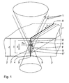
- Fig. 1 Based on Fig. 1 is to explain in Nahttiefencardi z power density modulated laser welding process.
- a focused laser beam 1 is used, for which the two joining partners 2, 3 are sufficiently transmissive of a suitable plastic, so that the laser beam 1 can penetrate its material on the one hand.
- the absorption of the material is so high that a part of the laser energy absorbed in the volume of the joining partner 2 and can be converted into thermal energy for welding.
- an infrared laser from the wavelength range of 0.7 to 2.5 ⁇ m and in particular a wavelength of 2 ⁇ m is suitable.
- the two joining partners 2, 3 are in Fig. 1 in a configuration in which the welding zone designated as a whole by S lies in the region of the mutually facing boundary surfaces 4, 5 of the abutment partners 2, 3 placed on butt joint.
- the invention attacks to the effect that is modulated by later still to be discussed constructive embodiments in the laser beam guidance and focusing the focus position 6 in the parallel to the direction of the Nahttiefe T extending z-direction, so with a certain frequency up and is traversed.
- Fig. 1 visualized by the exemplary drawn out, dashed or dotted focus positions shown 6 ', 6 ".
- the modulus amplitude in the z-direction can be used to define the seam depth T until shortly at the upper or lower edges 8, 9 of the interfaces 4, 5 of the joining partners 2, 3.
- the laser beam 1 is continuously along the weld seam 7 to be created in the interfaces 4, 5 in the x direction continuously stirred, as is the case with so-called. Contour welding.
- the feed rate v x in the x direction is at the modulation frequency or displacement speed v z of the focus position 6 correlated.
- the focus F should cover the entire weld depth T at least once or even several times in order to achieve a qualitatively perfect weld in the z-direction and x-direction over the seam depth T 7 produce.
- the modulation speed of the focus To select F to 1000 mm / s, so that the entire weld 7 is swept over its seam depth T once from the focus F.
- a device for laser beam welding in which the two joining partners 2, 3 are arranged in a transmitted-through configuration to each other.
- the devices have a schematically illustrated laser beam source 10, whose laser beam 1 is guided via a suitable optical waveguide 11 to the laser guiding and shaping device designated as a whole by 12. For the sake of simplicity, the latter will be referred to below as the laser processing head 12.
- a collimating lens 13 is provided corresponding to the divergent laser beam 1 emerging from the optical fiber 11 collimated and continues to the focusing lens 14. The latter focuses the laser beam 1 in the region of the joining partners 2, 3 with a specific focal length f.
- the focusing lens 14 is displaceably driven by a motor drive 15 in the direction of the lens axis.
- the focus F of the laser beam 1 can be modulated in the z direction, as shown by Fig. 1 has been described in detail.
- Fig. 2a the focus is approximately in the area of the interfaces 4, 5 of the two joining partners.
- the focusing lens 14 is displaced away from the collimating lens 13 in the direction of the joining partners 2, 3, so that the focus F is correspondingly displaced in the direction of the lower joining partner 3.
- the graphic representation is of course schematic and accordingly exaggerated.
- Fig. 2c is the focusing lens 14 on the original position acc. Fig. 2a shifted to the collimating lens 13, so that the focus F is shifted upward in the z direction.
- the focusing lens 15 can be set in its position corresponding to the desired modulation frequency and amplitude of the focus position 6, 6 ', 6 "in an oscillatory motion parallel to the z-axis.
- the modulation parameters can be varied before or during a welding process.
- a change for example, in a production of several variants or components on a system before the actual welding process done.
- it may also be useful to vary modulation parameters during a welding process and in particular on the individual component dependent along the feed path in the x direction.
- the variant shown lens 14 remains fixed in position, while the collimating lens 13 is provided with a drive 15.
- the collimating lens 13 is provided with a drive 15.
- the collimating lens 13 is positioned to each other so that the focus position 6 is again in the region of the boundary surfaces 4, 5 of the two joining partners 2, 3, by moving the collimating lens 13 away ( Fig. 3b ) from or closer to the focusing lens 14 (FIG. Fig. 3c ) the focus F be modulated.
- focus position 6 'and 6 "are exaggerated again with respect to the focus position 6 drawn drawn.
Landscapes
- Physics & Mathematics (AREA)
- Optics & Photonics (AREA)
- Engineering & Computer Science (AREA)
- Mechanical Engineering (AREA)
- Health & Medical Sciences (AREA)
- Electromagnetism (AREA)
- Toxicology (AREA)
- General Physics & Mathematics (AREA)
- Plasma & Fusion (AREA)
- Thermal Sciences (AREA)
- Lining Or Joining Of Plastics Or The Like (AREA)
- Laser Beam Processing (AREA)
Description
- Die Erfindung betrifft ein Verfahren zum Laserschweißen von zwei Fügepartnern aus Kunststoff, bei dem ein fokussierter Laserstrahl in eine Schweißzone im Bereich der einander zugewandten Grenzflächen der Fügepartner zur Bildung einer Schweißnaht mit einer bestimmten Nahttiefe zwischen den Fügepartnern eingestrahlt wird.
- Übliche Kunststoff-Laserschweißverfahren beruhen auf einem Eintrag von thermischer Energie mittels des fokussierten Laserstrahls in die Schweißzone, was zu einem Aufschmelzen der Fügepartner und der entsprechenden Bildung einer Schweißnaht dazwischen führt. Gängig ist in diesem Zusammenhang das sog. Durchstrahlschweißen, bei dem ein für die Laserstrahlung transmissiver Fügepartner auf einem dafür absorbierenden Fügepartner aufgelegt und der Laserstrahl durch den transmissiven Fügepartner auf den absorbierenden Fügepartner gestrahlt wird. Letzterer schmilzt auf, thermische Energie wird auf den transmissiven Fügepartner übertragen, der ebenfalls aufschmilzt, sodass insgesamt in dieser Schweißzone wieder eine Schweißnaht im Bereich der einander zugewandten Grenzflächen der Fügepartner gebildet wird.
- Die
JP 2005 001 172 A - Die
WO 2009/114 375 A2 zeigt eine Vorrichtung, die zum Laserschweißen von zwei Fügepartnern aus Kunststoff geeignet ist. Dabei wird ebenfalls ein fokussierter Laserstrahl in eine Schweißzone im Bereich der einander zugewandten Grenzflächen der Fügepartner zur Bildung einer Schweißnaht mit einer bestimmten Nahttiefe zwischen den Fügepartnern eingestrahlt. Diese Vorrichtung umfasst eine Laserstrahlquelle und eine Laserstrahl-Führungs- und Formungseinrichtung für den Laserstrahl, wobei eine Auslegung der Laserstrahlquelle und/oder der Laserstrahl-Führungs- und Formungseinrichtung derart gewählt ist, dass die Laser-Leistungsdichte während des Verschweiß-Vorganges in Richtung der Nahttiefe modulierbar ist. - Ähnliche Laserschweiß-Vorrichtungen zeigen die Druckschriften
US 2011/200802 A1 undWO 2011/074 072 A1 . - Aus der
US 2003/0090562 A1 ist ein Verfahren und eine Vorrichtung für das Laser-Durchstrahlschweißen bekannt, bei dem der Fokus des Laser-Bearbeitungsstrahls zum Ausgleich von Verwerfungen und ähnlichen Störstellen in der Schweißebene zwischen den beiden Fügepartnern senkrecht zur Schweißebene (z-Richtung) verschiebbar ist. Diese Verschiebung des Bauteils stellt eine träge Bewegung dar. Eine gezielte Einstellung der Wärmeeinflusszone durch hochfrequente Modulation der Z-Lage ist mit diesem System nicht möglich. - Die
DE 10 2007 036 838 A1 offenbart ein Verfahren zum Verbinden von Dokumentmaterialien unterschiedlichen Typs in einem Mehrschicht-Sicherheitsdokument-Körper, also beispielsweise einer Scheckkarte, wobei eine in einen Schichtaufbau eingebrachte elektromagnetischen Strahlung moduliert wird. Es handelt sich dabei um eine Amplituden- oder Frequenz-Modulation, eine Modulation der Fokus-Lage der Strahlung senkrecht zur Grenzfläche zwischen den einzelnen Schichten zeigt diese Druckschrift nicht. - Eine zunehmend an Bedeutung gewinnende Laser-Schweißtechnik für Kunststoffe ist das sog. Stumpfstoßschweißen. Mit Hilfe dieser Technik können beispielsweise zwei auf Stumpfstoß zueinander positionierte, für die Laserstrahlung transparente Fügepartner miteinander verschweißt werden, indem die einander zugewandten Grenzflächen mit Hilfe des Laserstrahls aufgeschmolzen und eine entsprechende Schweißnaht mit einem Vorschub des Laserstrahls entlang der Erstreckungsrichtung (x-Richtung) des Stoßbereichs hergestellt werden kann.
- Ein grundsätzliches Problem beim Laserschweißen von Fügepartnern aus Kunststoff ist die Tatsache, dass der Laserstrahl durch die Oberfläche eines oder beider Fügepartner in die Schweißzone eingestrahlt werden muss. Je nach Transmissions- oder Absorptionseigenschaften der verwendeten Kunststoffe kann zum einen die Oberfläche durch thermische Einwirkungen in Mitleidenschaft gezogen werden. Zum anderen kann ein Problem darin bestehen, dass die tatsächliche Schweißzone im Bereich der einander zugewandten Grenzflächen relativ begrenzt bezogen auf die Richtung der Nahttiefe (z-Richtung) ist, sodass die Festigkeit und Qualität der Naht verbesserungsbedürftig sein kann.
- Zusammenfassend besteht also ein Bedürfnis, die Schweißnahtausprägung in z-Richtung besser und werkstückorientierter steuern zu können.
- Diese Aufgabe der Erfindung wird in verfahrenstechnischer Hinsicht durch die im Patentanspruch 1 angegebenen Merkmale gelöst.
- Demnach liegt der Kern der vorliegenden Erfindung darin, die Laser-Leistungsdichte während des Verschweißvorgangs in Richtung der Nahttiefe (z-Richtung) zu modulieren. Dabei ist die Modulationsfrequenz der Laser-Leistungsdichte durch eine Modulationsfrequenz der Laser-Fokusposition in Z-Richtung definiert und mit der Vorschubgeschwindigkeit des Laserstrahls in Naht-Erstreckungsrichtung - also im üblichen Koordinatensystem in X-Richtung - derart korreliert, dass der Fokus während des Vorschubs des Laserstrahls in Naht-Erstreckungsrichtung mindestens einmal die Nahttiefe der Schweißnaht überstreicht.
- Die Modulationsfrequenz ist dementsprechend bei einem langsamen Vorschub in X-Richtung entsprechend geringer, wie bei einem schnellen Vorschub. Beim sog. Quasi-Simultanschweißen, bei dem eine geschlossene Kontur mehrfach in kurzen Zeitabständen nachgefahren wird, ist die Vorschubgeschwindigkeit um ein vielfaches höher, dementsprechend ist auch die Modulationsfrequenz in diesem Falle entsprechend höher zu wählen.
- Ergänzend kann neben der eigentlichen variablen Leistungsdichte diese Modulation auch durch einen variablen, entsprechend modulierten Fokusdurchmesser bezogen auf eine bestimmte z-Posititon der Nahttiefe realisiert werden.
- Aufgrund der modulationsbedingten Variabilität des Energieeintrags in z-Richtung kann in vorteilhafter Weise die Nahtgeometrie definiert beeinflusst werden. So kann beispielsweise bei einer Stumpfstoßschweißung zweier gleichermaßen transparenter Fügepartner bei Strahlungsdurchgang eines 2µm-Lasers durch eine Modulation der Z-Lage des Fokus die Energieeinbringung im Bereich der Naht über die Bauteildicke optimiert werden. So wird statt einer zentralen, eng begrenzten Schweißnaht geringer Nahttiefe durch die Modulation in Z-Richtung die Nahttiefe in Z-Richtung erhöht und kann optimal nahe an die oberen und unteren Stoßkanten der Fügepartner herangeführt werden, sodass einerseits eine möglichst große Nahttiefe entsteht, andererseits aber genügend Abstand zu den oberen und unteren Stoßkanten gehalten wird, das eine Oberflächenbeeinträchtigung vermieden wird.
- Ein bevorzugter Wellenlängenbereich des Laserstrahls für die Leistungsdichte-modulierte Laserschweißung liegt zwischen 0,7 µm und 2,5 µm, also im Infrarot-Bereich.
- Eine typische Auslegung einer entsprechenden Vorrichtung zum Laserschweißen, die eine Modulation der Laser-Leistungsdichte erlaubt, sieht eine entsprechende Auslegung der Laserstrahlquelle und/oder Laserstrahl-führungs- und Formungsreinrichtung vor, sodass die Laser-Leistungsdichte während des Verschweiß-Vorganges in Richtung der Nahttiefe modulierbar ist. Sofern die Laserstrahl-Führungs- und Formungseinrichtung eine Fokussiereinheit mit einer Kollimationslinse und einer Fokussierlinse umfasst, kann die Modulation durch eine Verschiebung der Kollimationslinse und/oder der Fokussierlinse entlang der Durchgangsrichtung des Laserstrahls (optische Achse) realisiert werden. Dazu sind vorzugsweise eine oder beide Linsen motorisch verstellbar. Eine Variante zu dieser Modulationstechnik ist die Modulation der Fokuslage des Laserstrahls durch eine Fokussiereinheit mit einer 3D-Scanner-Einheit.
- Weitere Merkmale, Einzelheiten und Vorteile der Erfindung ergeben sich aus der nachfolgenden Beschreibung anhand der beigefügten Zeichnungen. Es zeigen:
- Fig. 1
- eine perspektivische, in der Schweißzone weggeschnittene Schemadarstellung zweier Fügepartner bei einer Stumpfstoßschweißung,
- Fig. 2a bis c
- eine schematische Schnittdarstellung einer Laserstrahl-Führungs- und Formungseinrichtung mit verschiebbarer Fokussierlinse zur Fokuslagenmodulation, und
- Fig. 3a bis c
- eine schematische Schnittdarstellung einer Laserstrahl-Führungs- und Formungseinrichtung mit einer verschiebbaren Kollimationslinse zur Fokuslagenmodulierung.
- Anhand von
Fig. 1 ist das in Nahttiefenrichtung z Leistungsdichtemodulierte Laserschweißverfahren zu erläutern. So wird grundsätzlich ein fokussierter Laserstrahl 1 verwendet, für den die beiden Fügepartner 2, 3 aus einem geeigneten Kunststoff ausreichend transmissiv sind, sodass der Laserstrahl 1 deren Material einerseits durchdringen kann. Andererseits ist der Absorptionsgrad des Materials so hoch, dass ein Teil der Laserenergie im Volumen der Fügepartner 2 absorbiert und in thermische Energie zur Verschweißung umgewandelt werden kann. Geeignet ist beispielsweise ein Infrarot-Laser aus dem Wellenlängenbereich von 0,7 bis 2,5 µm und insbesondere einer Wellenlänge von 2 µm. Die beiden Fügepartner 2, 3 sind inFig. 1 in einer Konfiguration gezeigt, in der die als ganzes mit S bezeichnete Schweißzone im Bereich der einander zugewandten Grenzflächen 4, 5 der auf Stumpfstoß gesetzten Fügepartner 2, 3 liegt. - Die in
Fig. 1 gezeigte Position des Fokus F des Laserstrahls 1 würde zu einer lokal stark begrenzten Volumenabsorption der Laserleistung nur im Bereich um diese Fokusposition 6 mit einer entsprechend engen Ausbildung der Schweißnaht 7 über eine sehr begrenzte Nahttiefe T führen. - Hier greift nun die Erfindung dahingehend an, dass durch später noch zu erörternde konstruktive Ausgestaltungen in der Laserstrahl-Führung und -Fokussierung die Fokusposition 6 in der parallel zur Richtung der Nahttiefe T verlaufenden z-Richtung moduliert wird, also mit einer bestimmten Frequenz auf- und abgefahren wird. Dies ist in
Fig. 1 durch die beispielhaft herausgezeichneten, gestrichelt bzw. punktiert dargestellten Fokuspositionen 6', 6" visualisiert. - Insgesamt kann also durch die Modulationsamplitude in z-Richtung die Nahttiefe T definiert bis kurz an die Ober- bzw. Unterkanten 8, 9 der Grenzflächen 4, 5 der Fügepartner 2, 3 herangeführt werden.
- Wie in
Fig. 1 ferner angedeutet ist, wird der Laserstrahl 1 entlang der in den Grenzflächen 4, 5 zu erstellenden Schweißnaht 7 in x-Richtung kontinuierlich gerührt, wie dies beim sog. Konturschweißen der Fall ist. Die Vorschubgeschwindigkeit vx in x-Richtung ist mit der Modulationsfrequenz bzw. Verschiebegeschwindigkeit vz der Fokusposition 6 korreliert. Je nach dem von den Fügepartnern 2, 3 erreichten Absorptionsgrad für die Laserenergie sollte der Fokus F die gesamte Schweißnahttiefe T zumindest ein- oder auch mehrmals überstreichen, um eine in z-Richtung und x-Richtung über die Nahttiefe T gleichmäßig durchgehende, qualitativ einwandfreie Schweißnaht 7 herzustellen. So ist bei einem Fokus-Durchmesser DF von 0,1 mm, einer Nahttiefe von 1 mm bei einer Dicke d der Fügepartner 2, 3 von 2 mm und einer Vorschubgeschwindigkeit vx in x-Richtung von 100 mm/s die Modulationsgeschwindigkeit des Fokus F zu 1000 mm/s zu wählen, damit die gesamte Schweißnaht 7 über ihre Nahttiefe T einmal vom Fokus F überstrichen wird. - Wie aus
Fig. 1 ferner deutlich wird, kann über die entsprechende Einstellung der Nahttiefe T und deren Position in z-Richtung für die Schweißzone S ein ausreichender Abstand zu den Ober- und Unterkanten 8, 9 der Fügepartner 2, 3 eingehalten werden, sodass Schädigungen an den Sichtflächen der Fügepartner 2, 3 vermieden werden. - In
Fig. 2 a bis c und3 a bis c ist eine Vorrichtung zum Laserstrahlschweißen dargestellt, bei der die beiden Fügepartner 2, 3 in einer Durchstrahl-Konfiguration aufeinander angeordnet sind. Die Vorrichtungen weisen eine schematisch dargestellte Laserstrahlquelle 10 auf, deren Laserstrahl 1 über einen geeigneten Lichtleiter 11 zu der als Ganzes mit 12 bezeichneten Laser-Führungs- und Formungseinrichtung geführt ist. Letztere soll der Einfachheit halber im Folgenden mit Laserbearbeitungskopf 12 bezeichnet werden. - Im Laserbearbeitungskopf 12 ist eine Kollimationslinse 13 vorgesehen, die den divergenten, aus dem Lichtleiter 11 austretenden Laserstrahl 1 entsprechend kollimiert und zur Fokussierlinse 14 weiterführt. Letztere fokussiert den Laserstrahl 1 im Bereich der Fügepartner 2, 3 mit einer bestimmten Brennweite f.
- Bei der Ausführungsform gemäß
Fig. 2 ist die Fokussierlinse 14 durch einen motorischen Antrieb 15 in Richtung der Linsenachse verschiebbar angetrieben. Damit kann der Fokus F des Laserstrahls 1 in z-Richtung moduliert werden, wie dies anhand vonFig. 1 ausführlich beschrieben wurde. InFig. 2a liegt der Fokus etwa im Bereich der Grenzflächen 4, 5 der beiden Fügepartner. In der Position gem.Fig. 2b ist die Fokussierlinse 14 von der Kollimationslinse 13 weg in Richtung der Fügepartner 2, 3 verschoben, sodass der Fokus F entsprechend in Richtung zum unteren Fügepartner 3 verlagert ist. Die zeichnerische Darstellung ist hier natürlich schematisch und entsprechend übertrieben. - Gemäß
Fig. 2c ist die Fokussierlinse 14 über die ursprüngliche Position gem.Fig. 2a zur Kollimationslinse 13 hin verschoben, sodass der Fokus F nach oben in z-Richtung verschoben ist. - Mit Hilfe des Antriebs 15 kann also die Fokussierlinse 15 in ihre Position entsprechend der gewünschten Modulationsfrequenz und Amplitude der Fokusposition 6, 6', 6" in einer Oszillationsbewegung parallel zur z-Achse gesetzt werden.
- Es ist darauf hinzuweisen, dass für eine entsprechende Steuerung des Antriebs 15 die Modulationsparameter vor oder während eines Schweißprozesses variiert werden können. So kann eine Änderung beispielsweise bei einer Produktion von mehreren Varianten oder Bauteilen auf einer Anlage vor dem eigentlichen Schweißprozess erfolgen. Bei einer entsprechenden Nahtdiagnostik kann es auch sinnvoll sein, Modulationsparameter während eines Schweißprozesses und insbesondere vom individuellen Bauteil abhängig entlang des Vorschubweges in x-Richtung zu variieren.
- Bei der in den
Fig. 3a bis c gezeigten Variante bleibt die Fokussierlinse 14 lagefixiert, während die Kollimationslinse 13 mit einem Antrieb 15 versehen ist. Ausgehend von der inFig. 3a gezeigten Position, bei der Kollimations- und Fokussierlinse, 13, 14 so zueinander positioniert sind, dass die Fokusposition 6 wieder im Bereich der Grenzflächen 4, 5 der beiden Fügepartner 2, 3 liegt, kann durch eine Verschiebung der Kollimationslinse 13 weg (Fig. 3b ) von der bzw. näher an die Fokussierlinse 14 (Fig. 3c ) der Fokus F lagemoduliert werden. Die inFig. 3b und 3c gezeigten Fokusposition 6' und 6" sind dabei wieder übertrieben gegenüber der Fokusposition 6 verschoben gezeichnet.
Claims (4)
- Verfahren zum Laserschweißen von zwei Fügepartnern aus Kunststoff, bei dem ein fokussierter Laserstrahl (1) in eine Schweißzone (S) im Bereich der einander zugewandten Grenzflächen (4, 5) der Fügepartner (2, 3) zur Bildung einer Schweißnaht (7) mit einer bestimmten Nahttiefe (T) zwischen den Fügepartnern (2, 3) eingestrahlt wird, wobei die Laser-Leistungsdichte während des Verschweißvorganges in Richtung (z) der Nahttiefe (T) in der Schweißzone (S) moduliert wird,
dadurch gekennzeichnet, dass
die Modulation der Laser-Leistungsdichte durch eine Modulation der Fokusposition (6, 6', 6") des Laserstrahls (1) in Richtung (z) der Nahttiefe (T) erfolgt, wobei die Modulationsfrequenz der Laser-Leistungsdichte in Richtung (z) der Nahttiefe (T) mit einer Vorschubgeschwindigkeit des Laserstrahls (1) in Naht-Erstreckungsrichtung (x) derart korreliert ist, dass der Fokus (F) während des Vorschubs des Laserstrahls (1) in Naht-Erstreckungsrichtung (x) mindestens einmal die Nahttiefe (T) der Schweißnaht (7) überstreicht. - Verfahren nach Anspruch 1, dadurch gekennzeichnet, dass die Modulation der Laser-Leistungsdichte durch eine Modulation des Durchmessers (DF) des Laserstrahls (1) in seinem Fokus (F) erfolgt.
- Verfahren nach einem der vorgenannten Ansprüche, dadurch gekennzeichnet, dass mit der Schweißnaht (7) zwei auf Stumpfstoß zueinander positionierte Fügepartner (2, 3) miteinander verbunden werden.
- Verfahren nach einem der vorgenannten Ansprüche, dadurch gekennzeichnet, dass der Wellenlängenbereich des Laserstrahls (1) zwischen 0,7 µm und 2,5 µm liegt.
Applications Claiming Priority (2)
| Application Number | Priority Date | Filing Date | Title |
|---|---|---|---|
| DE102011081554A DE102011081554A1 (de) | 2011-08-25 | 2011-08-25 | Verfahren und Vorrichtung zum Laserschweißen von zwei Fügepartnern aus Kunststoff |
| PCT/EP2012/066167 WO2013026816A1 (de) | 2011-08-25 | 2012-08-20 | Verfahren und vorrichtung zum laserschweissen von zwei fügepartnern aus kunststoff |
Publications (2)
| Publication Number | Publication Date |
|---|---|
| EP2747984A1 EP2747984A1 (de) | 2014-07-02 |
| EP2747984B1 true EP2747984B1 (de) | 2015-07-15 |
Family
ID=46785377
Family Applications (1)
| Application Number | Title | Priority Date | Filing Date |
|---|---|---|---|
| EP12753681.1A Not-in-force EP2747984B1 (de) | 2011-08-25 | 2012-08-20 | Verfahren und vorrichtung zum laserschweissen von zwei fügepartnern aus kunststoff |
Country Status (8)
| Country | Link |
|---|---|
| US (1) | US20140216648A1 (de) |
| EP (1) | EP2747984B1 (de) |
| JP (1) | JP2014529522A (de) |
| KR (1) | KR20140058571A (de) |
| CN (1) | CN103842156B (de) |
| DE (1) | DE102011081554A1 (de) |
| DK (1) | DK2747984T3 (de) |
| WO (1) | WO2013026816A1 (de) |
Families Citing this family (21)
| Publication number | Priority date | Publication date | Assignee | Title |
|---|---|---|---|---|
| DE102013108535A1 (de) | 2013-08-07 | 2015-02-12 | SMR Patents S.à.r.l. | Verfahren zum Herstellen einer Platine, Platine und Rückblickvorrichtung |
| US10555415B2 (en) | 2013-08-07 | 2020-02-04 | SMR Patents S.à.r.l. | Method for manufacturing a printed circuit board |
| WO2015127473A1 (en) | 2014-02-24 | 2015-08-27 | Pregis Innovative Packaging Llc | Recipe controlled device for making packaging materials |
| PL2957418T3 (pl) * | 2014-06-19 | 2020-09-21 | Marelli Automotive Lighting Italy S.p.A. | Urządzenie do wytwarzania reflektora samochodowego i sposób równoczesnego zgrzewania laserowego reflektora samochodowego |
| DE102015109183A1 (de) | 2015-06-10 | 2016-12-15 | Fachhochschule Schmalkalden | Verfahren zum Verbinden von zwei Fügepartnern aus Kunststoff |
| DE102016206400A1 (de) * | 2016-04-15 | 2017-10-19 | Bühler Motor GmbH | Stellantrieb und Verfahren zur Herstellung eines Stellantriebs |
| DE102016116608A1 (de) | 2016-09-06 | 2018-03-08 | Invendo Medical Gmbh | Lineares Laserschweißen von rohrförmigen Kunststoffelementen |
| DE102017200080A1 (de) * | 2017-01-05 | 2018-07-05 | Volkswagen Aktiengesellschaft | Laserwerkzeug mit Hohlwellenantrieb und nicht-rotierender Linse |
| EP3565687B1 (de) | 2017-01-05 | 2023-08-09 | Volkswagen Aktiengesellschaft | Laserwerkzeug mit fokusverstelleinheit |
| US10889064B1 (en) | 2017-04-26 | 2021-01-12 | Mercury Plastics Llc | Process for laser welding of crosslinked polyethylene |
| EP3517241A1 (de) * | 2018-01-29 | 2019-07-31 | Bystronic Laser AG | Optische vorrichtung zum formen eines elektromagnetischen wellenstrahls und verwendung davon, strahlbehandlungsvorrichtung und verwendung davon sowie strahlbehandlungsverfahren |
| DE102018220447A1 (de) * | 2018-11-28 | 2020-05-28 | Trumpf Laser Gmbh | Verfahren zum Stoßschweißen mittels eines UKP-Laserstrahls sowie aus Einzelteilen zusammengefügtes optisches Element |
| DE102018220477A1 (de) | 2018-11-28 | 2020-05-28 | Trumpf Laser Gmbh | Verfahren zum Laserschweißen einer Lichtleitfaser in einem Lochelement mittels eines UKP-Laserstrahls sowie zugehöriges optisches Element |
| EP3741489A1 (de) * | 2019-05-24 | 2020-11-25 | Linde GmbH | Vorrichtung zur reinigung und kühlung eines werkstücks während der generativen drahtlichtbogenfertigung (waam) |
| WO2021025889A1 (en) | 2019-08-02 | 2021-02-11 | Canon Virginia, Inc. | Laser welding plastic segments |
| CN110435160A (zh) * | 2019-09-09 | 2019-11-12 | 广东利元亨智能装备股份有限公司 | 一种激光焊接头及激光焊接方法 |
| CN111185666B (zh) * | 2020-04-13 | 2020-08-04 | 中国航空制造技术研究院 | 一种扫描激光-tig电弧复合深熔焊接方法 |
| CN113751862A (zh) * | 2020-05-29 | 2021-12-07 | 方强 | 基于两片透镜的变焦对焦激光切割头 |
| DE102021118593A1 (de) | 2021-07-19 | 2023-01-19 | Trumpf Laser Gmbh | Verfahren zum Fügen mindestens zweier Fügepartner |
| CN115106655B (zh) * | 2022-06-14 | 2024-04-12 | 中国科学院上海光学精密机械研究所 | 一种用于中厚板的激光焊接方法 |
| CN116461104A (zh) * | 2023-03-29 | 2023-07-21 | 深圳泰德激光技术股份有限公司 | 激光塑料焊接方法 |
Family Cites Families (8)
| Publication number | Priority date | Publication date | Assignee | Title |
|---|---|---|---|---|
| US6816182B2 (en) * | 2000-03-14 | 2004-11-09 | Masanori Kubota | Radiation welding and imaging apparatus and method for using the same |
| JP4230826B2 (ja) * | 2003-06-10 | 2009-02-25 | 浜松ホトニクス株式会社 | レーザ加工方法 |
| US9138913B2 (en) * | 2005-09-08 | 2015-09-22 | Imra America, Inc. | Transparent material processing with an ultrashort pulse laser |
| DE102006042280A1 (de) * | 2005-09-08 | 2007-06-06 | IMRA America, Inc., Ann Arbor | Bearbeitung von transparentem Material mit einem Ultrakurzpuls-Laser |
| TWI352001B (en) * | 2005-11-18 | 2011-11-11 | Hon Hai Prec Ind Co Ltd | Laser machining system and process for laser machi |
| DE102007036838A1 (de) * | 2007-08-02 | 2009-02-05 | Bundesdruckerei Gmbh | Verfahren zum Verbinden von Dokumentmaterialien unterschiedlichen Typs in einem Mehrschichtsicherheitsdokumentkörper |
| WO2011074072A1 (ja) * | 2009-12-15 | 2011-06-23 | 浜松ホトニクス株式会社 | 樹脂溶着方法 |
| US20110200802A1 (en) * | 2010-02-16 | 2011-08-18 | Shenping Li | Laser Welding of Polymeric Materials |
-
2011
- 2011-08-25 DE DE102011081554A patent/DE102011081554A1/de not_active Withdrawn
-
2012
- 2012-08-20 DK DK12753681.1T patent/DK2747984T3/en active
- 2012-08-20 CN CN201280041347.XA patent/CN103842156B/zh not_active Expired - Fee Related
- 2012-08-20 US US14/240,965 patent/US20140216648A1/en not_active Abandoned
- 2012-08-20 KR KR1020147004463A patent/KR20140058571A/ko not_active Withdrawn
- 2012-08-20 EP EP12753681.1A patent/EP2747984B1/de not_active Not-in-force
- 2012-08-20 JP JP2014526462A patent/JP2014529522A/ja active Pending
- 2012-08-20 WO PCT/EP2012/066167 patent/WO2013026816A1/de not_active Ceased
Also Published As
| Publication number | Publication date |
|---|---|
| DK2747984T3 (en) | 2015-10-26 |
| JP2014529522A (ja) | 2014-11-13 |
| US20140216648A1 (en) | 2014-08-07 |
| WO2013026816A1 (de) | 2013-02-28 |
| KR20140058571A (ko) | 2014-05-14 |
| CN103842156B (zh) | 2016-03-09 |
| EP2747984A1 (de) | 2014-07-02 |
| DE102011081554A1 (de) | 2013-02-28 |
| CN103842156A (zh) | 2014-06-04 |
Similar Documents
| Publication | Publication Date | Title |
|---|---|---|
| EP2747984B1 (de) | Verfahren und vorrichtung zum laserschweissen von zwei fügepartnern aus kunststoff | |
| EP2978588B1 (de) | Verfahren und vorrichtung zum verschweissen zweier fügepartner aus thermoplastischen kunststoffen entlang einer schweissnaht mittels laser | |
| EP0997261B1 (de) | Laserfügeverfahren und Vorrichtung zum Verbinden von verschiedenen Werkstücken aus Kunststoff oder Kunststoff mit anderen Materialien | |
| DE102012008940B4 (de) | Verfahren zum Fügen von mindestens zwei Werkstücken | |
| DE69627802T2 (de) | Verfahren und Vorrichtung zum Schweissen von Werkstücken mittels zwei oder mehrerer Laserstrahlen, deren Spots von einer Seite der Schweissrichtung zur anderen Seite oszilliert sind | |
| EP0751865B1 (de) | Werkstück aus kunststoff und herstellungsverfahren für ein derartiges werkstück | |
| DE102007038502B4 (de) | Verfahren zum Fügen von mindestens zwei Werkstücken mittels eines Laserstrahls | |
| DE102014203025A1 (de) | Verfahren zum Laserstrahlschweißen und Schweißkopf | |
| DE102009057997A1 (de) | Verfahren zum Verschweißen von zwei Metallbauteilen | |
| DE102016222357A1 (de) | Verfahren zum Tiefschweißen eines Werkstücks, mit Einstrahlen eines Laserstrahls in die von einem anderen Laserstrahl erzeugte Kapillaröffnung | |
| DE102007035717A1 (de) | Laserstrahlschweißvorrichtung sowie Laserstrahlschweißverfahren | |
| WO2004058485A1 (de) | Verfahren und vorrichtung zum verschweissen thermoplastischer kunststoff-formteile, insbesondere zum konturschweissen dreidimensionaler formteile | |
| DE10053402B4 (de) | Verfahren und Vorrichtung zum thermischen Fügen von Bauteilen aus silikatischen Werkstoffen, Silikat-Verbundwerkstoffen und Silikat-Kompositwerkstoffen | |
| DE102018205325A1 (de) | Verfahren zum Laserschweißen von transparenten Werkstücken und zugehörige Laserbearbeitungsmaschine | |
| DE102004030619A1 (de) | Verfahren zum Verbinden von Werkstücken aus Kunststoff | |
| EP3414044B1 (de) | Verfahren zum herstellen mindestens eines teilbereichs einer schicht eines dreidimensionalen bauteils | |
| EP3849782B1 (de) | Druckkopf für eine druckvorrichtung zum dreidimensionalen aufbringen eines materials, druckvorrichtung sowie verfahren | |
| DE112006000949T5 (de) | Laserschweisssystem | |
| EP3541560A1 (de) | LASERPRESSSCHWEIßEN | |
| WO2018041463A1 (de) | VERFAHREN UND VORRICHTUNG ZUM VERSCHWEIßEN VON FÜGEPARTNERN | |
| DE102005018727A1 (de) | Verfahren und Vorrichtung zum Verschweißen von zwei Werkstücken aus thermoplastischen Kunststoffen mittels Laserstrahlung | |
| DE112021003368T5 (de) | Laserschweissverfahren und laserschweissvorrichtung | |
| DE202015009238U1 (de) | Vorrichtung zum lasergestützten Trennen eines Werkstücks | |
| DE19961361A1 (de) | Vorrichtung zum Konfektionieren von bewegten Kunststofffolienbahnen | |
| EP3419811B1 (de) | Verfahren zum schweissen einer verbindung zwischen einer ersten fügefläche eines ersten formteils und einer zweiten fügefläche eines zweiten formteils |
Legal Events
| Date | Code | Title | Description |
|---|---|---|---|
| PUAI | Public reference made under article 153(3) epc to a published international application that has entered the european phase |
Free format text: ORIGINAL CODE: 0009012 |
|
| 17P | Request for examination filed |
Effective date: 20140207 |
|
| AK | Designated contracting states |
Kind code of ref document: A1 Designated state(s): AL AT BE BG CH CY CZ DE DK EE ES FI FR GB GR HR HU IE IS IT LI LT LU LV MC MK MT NL NO PL PT RO RS SE SI SK SM TR |
|
| DAX | Request for extension of the european patent (deleted) | ||
| GRAP | Despatch of communication of intention to grant a patent |
Free format text: ORIGINAL CODE: EPIDOSNIGR1 |
|
| INTG | Intention to grant announced |
Effective date: 20150210 |
|
| GRAS | Grant fee paid |
Free format text: ORIGINAL CODE: EPIDOSNIGR3 |
|
| GRAA | (expected) grant |
Free format text: ORIGINAL CODE: 0009210 |
|
| AK | Designated contracting states |
Kind code of ref document: B1 Designated state(s): AL AT BE BG CH CY CZ DE DK EE ES FI FR GB GR HR HU IE IS IT LI LT LU LV MC MK MT NL NO PL PT RO RS SE SI SK SM TR |
|
| REG | Reference to a national code |
Ref country code: CH Ref legal event code: EP Ref country code: GB Ref legal event code: FG4D Free format text: NOT ENGLISH |
|
| REG | Reference to a national code |
Ref country code: IE Ref legal event code: FG4D Free format text: LANGUAGE OF EP DOCUMENT: GERMAN |
|
| REG | Reference to a national code |
Ref country code: AT Ref legal event code: REF Ref document number: 736560 Country of ref document: AT Kind code of ref document: T Effective date: 20150815 |
|
| REG | Reference to a national code |
Ref country code: DE Ref legal event code: R096 Ref document number: 502012003822 Country of ref document: DE |
|
| REG | Reference to a national code |
Ref country code: NL Ref legal event code: T3 |
|
| REG | Reference to a national code |
Ref country code: DK Ref legal event code: T3 Effective date: 20151020 |
|
| REG | Reference to a national code |
Ref country code: LT Ref legal event code: MG4D |
|
| PG25 | Lapsed in a contracting state [announced via postgrant information from national office to epo] |
Ref country code: LV Free format text: LAPSE BECAUSE OF FAILURE TO SUBMIT A TRANSLATION OF THE DESCRIPTION OR TO PAY THE FEE WITHIN THE PRESCRIBED TIME-LIMIT Effective date: 20150715 Ref country code: GR Free format text: LAPSE BECAUSE OF FAILURE TO SUBMIT A TRANSLATION OF THE DESCRIPTION OR TO PAY THE FEE WITHIN THE PRESCRIBED TIME-LIMIT Effective date: 20151016 Ref country code: NO Free format text: LAPSE BECAUSE OF FAILURE TO SUBMIT A TRANSLATION OF THE DESCRIPTION OR TO PAY THE FEE WITHIN THE PRESCRIBED TIME-LIMIT Effective date: 20151015 Ref country code: LT Free format text: LAPSE BECAUSE OF FAILURE TO SUBMIT A TRANSLATION OF THE DESCRIPTION OR TO PAY THE FEE WITHIN THE PRESCRIBED TIME-LIMIT Effective date: 20150715 |
|
| PG25 | Lapsed in a contracting state [announced via postgrant information from national office to epo] |
Ref country code: PL Free format text: LAPSE BECAUSE OF FAILURE TO SUBMIT A TRANSLATION OF THE DESCRIPTION OR TO PAY THE FEE WITHIN THE PRESCRIBED TIME-LIMIT Effective date: 20150715 Ref country code: PT Free format text: LAPSE BECAUSE OF FAILURE TO SUBMIT A TRANSLATION OF THE DESCRIPTION OR TO PAY THE FEE WITHIN THE PRESCRIBED TIME-LIMIT Effective date: 20151116 Ref country code: RS Free format text: LAPSE BECAUSE OF FAILURE TO SUBMIT A TRANSLATION OF THE DESCRIPTION OR TO PAY THE FEE WITHIN THE PRESCRIBED TIME-LIMIT Effective date: 20150715 Ref country code: SE Free format text: LAPSE BECAUSE OF FAILURE TO SUBMIT A TRANSLATION OF THE DESCRIPTION OR TO PAY THE FEE WITHIN THE PRESCRIBED TIME-LIMIT Effective date: 20150715 Ref country code: ES Free format text: LAPSE BECAUSE OF FAILURE TO SUBMIT A TRANSLATION OF THE DESCRIPTION OR TO PAY THE FEE WITHIN THE PRESCRIBED TIME-LIMIT Effective date: 20150715 Ref country code: HR Free format text: LAPSE BECAUSE OF FAILURE TO SUBMIT A TRANSLATION OF THE DESCRIPTION OR TO PAY THE FEE WITHIN THE PRESCRIBED TIME-LIMIT Effective date: 20150715 |
|
| REG | Reference to a national code |
Ref country code: CH Ref legal event code: PL |
|
| REG | Reference to a national code |
Ref country code: DE Ref legal event code: R097 Ref document number: 502012003822 Country of ref document: DE |
|
| PG25 | Lapsed in a contracting state [announced via postgrant information from national office to epo] |
Ref country code: LI Free format text: LAPSE BECAUSE OF NON-PAYMENT OF DUE FEES Effective date: 20150831 Ref country code: MC Free format text: LAPSE BECAUSE OF FAILURE TO SUBMIT A TRANSLATION OF THE DESCRIPTION OR TO PAY THE FEE WITHIN THE PRESCRIBED TIME-LIMIT Effective date: 20150715 Ref country code: SK Free format text: LAPSE BECAUSE OF FAILURE TO SUBMIT A TRANSLATION OF THE DESCRIPTION OR TO PAY THE FEE WITHIN THE PRESCRIBED TIME-LIMIT Effective date: 20150715 Ref country code: EE Free format text: LAPSE BECAUSE OF FAILURE TO SUBMIT A TRANSLATION OF THE DESCRIPTION OR TO PAY THE FEE WITHIN THE PRESCRIBED TIME-LIMIT Effective date: 20150715 Ref country code: IT Free format text: LAPSE BECAUSE OF FAILURE TO SUBMIT A TRANSLATION OF THE DESCRIPTION OR TO PAY THE FEE WITHIN THE PRESCRIBED TIME-LIMIT Effective date: 20150715 Ref country code: CZ Free format text: LAPSE BECAUSE OF FAILURE TO SUBMIT A TRANSLATION OF THE DESCRIPTION OR TO PAY THE FEE WITHIN THE PRESCRIBED TIME-LIMIT Effective date: 20150715 Ref country code: CH Free format text: LAPSE BECAUSE OF NON-PAYMENT OF DUE FEES Effective date: 20150831 |
|
| PLBE | No opposition filed within time limit |
Free format text: ORIGINAL CODE: 0009261 |
|
| STAA | Information on the status of an ep patent application or granted ep patent |
Free format text: STATUS: NO OPPOSITION FILED WITHIN TIME LIMIT |
|
| PG25 | Lapsed in a contracting state [announced via postgrant information from national office to epo] |
Ref country code: RO Free format text: LAPSE BECAUSE OF FAILURE TO SUBMIT A TRANSLATION OF THE DESCRIPTION OR TO PAY THE FEE WITHIN THE PRESCRIBED TIME-LIMIT Effective date: 20150715 |
|
| REG | Reference to a national code |
Ref country code: IE Ref legal event code: MM4A |
|
| REG | Reference to a national code |
Ref country code: FR Ref legal event code: ST Effective date: 20160429 |
|
| 26N | No opposition filed |
Effective date: 20160418 |
|
| PG25 | Lapsed in a contracting state [announced via postgrant information from national office to epo] |
Ref country code: IS Free format text: LAPSE BECAUSE OF FAILURE TO SUBMIT A TRANSLATION OF THE DESCRIPTION OR TO PAY THE FEE WITHIN THE PRESCRIBED TIME-LIMIT Effective date: 20150715 |
|
| PG25 | Lapsed in a contracting state [announced via postgrant information from national office to epo] |
Ref country code: IE Free format text: LAPSE BECAUSE OF NON-PAYMENT OF DUE FEES Effective date: 20150820 |
|
| PG25 | Lapsed in a contracting state [announced via postgrant information from national office to epo] |
Ref country code: SI Free format text: LAPSE BECAUSE OF FAILURE TO SUBMIT A TRANSLATION OF THE DESCRIPTION OR TO PAY THE FEE WITHIN THE PRESCRIBED TIME-LIMIT Effective date: 20150715 Ref country code: FR Free format text: LAPSE BECAUSE OF NON-PAYMENT OF DUE FEES Effective date: 20150915 |
|
| PG25 | Lapsed in a contracting state [announced via postgrant information from national office to epo] |
Ref country code: MT Free format text: LAPSE BECAUSE OF FAILURE TO SUBMIT A TRANSLATION OF THE DESCRIPTION OR TO PAY THE FEE WITHIN THE PRESCRIBED TIME-LIMIT Effective date: 20150715 |
|
| PG25 | Lapsed in a contracting state [announced via postgrant information from national office to epo] |
Ref country code: HU Free format text: LAPSE BECAUSE OF FAILURE TO SUBMIT A TRANSLATION OF THE DESCRIPTION OR TO PAY THE FEE WITHIN THE PRESCRIBED TIME-LIMIT; INVALID AB INITIO Effective date: 20120820 Ref country code: SM Free format text: LAPSE BECAUSE OF FAILURE TO SUBMIT A TRANSLATION OF THE DESCRIPTION OR TO PAY THE FEE WITHIN THE PRESCRIBED TIME-LIMIT Effective date: 20150715 Ref country code: BG Free format text: LAPSE BECAUSE OF FAILURE TO SUBMIT A TRANSLATION OF THE DESCRIPTION OR TO PAY THE FEE WITHIN THE PRESCRIBED TIME-LIMIT Effective date: 20150715 |
|
| PG25 | Lapsed in a contracting state [announced via postgrant information from national office to epo] |
Ref country code: CY Free format text: LAPSE BECAUSE OF FAILURE TO SUBMIT A TRANSLATION OF THE DESCRIPTION OR TO PAY THE FEE WITHIN THE PRESCRIBED TIME-LIMIT Effective date: 20150715 |
|
| PG25 | Lapsed in a contracting state [announced via postgrant information from national office to epo] |
Ref country code: BE Free format text: LAPSE BECAUSE OF NON-PAYMENT OF DUE FEES Effective date: 20150831 |
|
| PGFP | Annual fee paid to national office [announced via postgrant information from national office to epo] |
Ref country code: NL Payment date: 20170823 Year of fee payment: 6 |
|
| PGFP | Annual fee paid to national office [announced via postgrant information from national office to epo] |
Ref country code: FI Payment date: 20170821 Year of fee payment: 6 |
|
| PG25 | Lapsed in a contracting state [announced via postgrant information from national office to epo] |
Ref country code: LU Free format text: LAPSE BECAUSE OF NON-PAYMENT OF DUE FEES Effective date: 20150820 |
|
| PGFP | Annual fee paid to national office [announced via postgrant information from national office to epo] |
Ref country code: AT Payment date: 20170725 Year of fee payment: 6 |
|
| PG25 | Lapsed in a contracting state [announced via postgrant information from national office to epo] |
Ref country code: MK Free format text: LAPSE BECAUSE OF FAILURE TO SUBMIT A TRANSLATION OF THE DESCRIPTION OR TO PAY THE FEE WITHIN THE PRESCRIBED TIME-LIMIT Effective date: 20150715 Ref country code: TR Free format text: LAPSE BECAUSE OF FAILURE TO SUBMIT A TRANSLATION OF THE DESCRIPTION OR TO PAY THE FEE WITHIN THE PRESCRIBED TIME-LIMIT Effective date: 20150715 |
|
| PG25 | Lapsed in a contracting state [announced via postgrant information from national office to epo] |
Ref country code: AL Free format text: LAPSE BECAUSE OF FAILURE TO SUBMIT A TRANSLATION OF THE DESCRIPTION OR TO PAY THE FEE WITHIN THE PRESCRIBED TIME-LIMIT Effective date: 20150715 |
|
| REG | Reference to a national code |
Ref country code: NL Ref legal event code: MM Effective date: 20180901 |
|
| REG | Reference to a national code |
Ref country code: AT Ref legal event code: MM01 Ref document number: 736560 Country of ref document: AT Kind code of ref document: T Effective date: 20180820 |
|
| PG25 | Lapsed in a contracting state [announced via postgrant information from national office to epo] |
Ref country code: FI Free format text: LAPSE BECAUSE OF NON-PAYMENT OF DUE FEES Effective date: 20180820 Ref country code: AT Free format text: LAPSE BECAUSE OF NON-PAYMENT OF DUE FEES Effective date: 20180820 |
|
| PG25 | Lapsed in a contracting state [announced via postgrant information from national office to epo] |
Ref country code: NL Free format text: LAPSE BECAUSE OF NON-PAYMENT OF DUE FEES Effective date: 20180901 |
|
| PGFP | Annual fee paid to national office [announced via postgrant information from national office to epo] |
Ref country code: DK Payment date: 20210820 Year of fee payment: 10 Ref country code: GB Payment date: 20210824 Year of fee payment: 10 |
|
| REG | Reference to a national code |
Ref country code: DK Ref legal event code: EBP Effective date: 20220831 |
|
| GBPC | Gb: european patent ceased through non-payment of renewal fee |
Effective date: 20220820 |
|
| PG25 | Lapsed in a contracting state [announced via postgrant information from national office to epo] |
Ref country code: DK Free format text: LAPSE BECAUSE OF NON-PAYMENT OF DUE FEES Effective date: 20220831 |
|
| PG25 | Lapsed in a contracting state [announced via postgrant information from national office to epo] |
Ref country code: GB Free format text: LAPSE BECAUSE OF NON-PAYMENT OF DUE FEES Effective date: 20220820 |
|
| PGFP | Annual fee paid to national office [announced via postgrant information from national office to epo] |
Ref country code: DE Payment date: 20241025 Year of fee payment: 13 |
|
| REG | Reference to a national code |
Ref country code: DE Ref legal event code: R119 Ref document number: 502012003822 Country of ref document: DE |