EP2748004B1 - Machine et procédé d'impression de bandes d'impression - Google Patents
Machine et procédé d'impression de bandes d'impression Download PDFInfo
- Publication number
- EP2748004B1 EP2748004B1 EP12748224.8A EP12748224A EP2748004B1 EP 2748004 B1 EP2748004 B1 EP 2748004B1 EP 12748224 A EP12748224 A EP 12748224A EP 2748004 B1 EP2748004 B1 EP 2748004B1
- Authority
- EP
- European Patent Office
- Prior art keywords
- web
- material web
- sensor
- support
- station
- Prior art date
- Legal status (The legal status is an assumption and is not a legal conclusion. Google has not performed a legal analysis and makes no representation as to the accuracy of the status listed.)
- Active
Links
Images



Classifications
-
- B—PERFORMING OPERATIONS; TRANSPORTING
- B41—PRINTING; LINING MACHINES; TYPEWRITERS; STAMPS
- B41J—TYPEWRITERS; SELECTIVE PRINTING MECHANISMS, i.e. MECHANISMS PRINTING OTHERWISE THAN FROM A FORME; CORRECTION OF TYPOGRAPHICAL ERRORS
- B41J11/00—Devices or arrangements of selective printing mechanisms, e.g. ink-jet printers or thermal printers, for supporting or handling copy material in sheet or web form
- B41J11/0095—Detecting means for copy material, e.g. for detecting or sensing presence of copy material or its leading or trailing end
-
- G—PHYSICS
- G01—MEASURING; TESTING
- G01J—MEASUREMENT OF INTENSITY, VELOCITY, SPECTRAL CONTENT, POLARISATION, PHASE OR PULSE CHARACTERISTICS OF INFRARED, VISIBLE OR ULTRAVIOLET LIGHT; COLORIMETRY; RADIATION PYROMETRY
- G01J1/00—Photometry, e.g. photographic exposure meter
- G01J1/02—Details
- G01J1/0271—Housings; Attachments or accessories for photometers
-
- B—PERFORMING OPERATIONS; TRANSPORTING
- B41—PRINTING; LINING MACHINES; TYPEWRITERS; STAMPS
- B41F—PRINTING MACHINES OR PRESSES
- B41F33/00—Indicating, counting, warning, control or safety devices
- B41F33/0036—Devices for scanning or checking the printed matter for quality control
-
- B—PERFORMING OPERATIONS; TRANSPORTING
- B41—PRINTING; LINING MACHINES; TYPEWRITERS; STAMPS
- B41F—PRINTING MACHINES OR PRESSES
- B41F33/00—Indicating, counting, warning, control or safety devices
- B41F33/02—Arrangements of indicating devices, e.g. counters
-
- G—PHYSICS
- G01—MEASURING; TESTING
- G01J—MEASUREMENT OF INTENSITY, VELOCITY, SPECTRAL CONTENT, POLARISATION, PHASE OR PULSE CHARACTERISTICS OF INFRARED, VISIBLE OR ULTRAVIOLET LIGHT; COLORIMETRY; RADIATION PYROMETRY
- G01J1/00—Photometry, e.g. photographic exposure meter
- G01J1/02—Details
- G01J1/04—Optical or mechanical part supplementary adjustable parts
- G01J1/0403—Mechanical elements; Supports for optical elements; Scanning arrangements
-
- G—PHYSICS
- G01—MEASURING; TESTING
- G01J—MEASUREMENT OF INTENSITY, VELOCITY, SPECTRAL CONTENT, POLARISATION, PHASE OR PULSE CHARACTERISTICS OF INFRARED, VISIBLE OR ULTRAVIOLET LIGHT; COLORIMETRY; RADIATION PYROMETRY
- G01J1/00—Photometry, e.g. photographic exposure meter
- G01J1/02—Details
- G01J1/08—Arrangements of light sources specially adapted for photometry standard sources, also using luminescent or radioactive material
-
- G—PHYSICS
- G01—MEASURING; TESTING
- G01J—MEASUREMENT OF INTENSITY, VELOCITY, SPECTRAL CONTENT, POLARISATION, PHASE OR PULSE CHARACTERISTICS OF INFRARED, VISIBLE OR ULTRAVIOLET LIGHT; COLORIMETRY; RADIATION PYROMETRY
- G01J3/00—Spectrometry; Spectrophotometry; Monochromators; Measuring colours
- G01J3/02—Details
- G01J3/0202—Mechanical elements; Supports for optical elements
-
- G—PHYSICS
- G01—MEASURING; TESTING
- G01J—MEASUREMENT OF INTENSITY, VELOCITY, SPECTRAL CONTENT, POLARISATION, PHASE OR PULSE CHARACTERISTICS OF INFRARED, VISIBLE OR ULTRAVIOLET LIGHT; COLORIMETRY; RADIATION PYROMETRY
- G01J3/00—Spectrometry; Spectrophotometry; Monochromators; Measuring colours
- G01J3/02—Details
- G01J3/0267—Sample holders for colorimetry
-
- G—PHYSICS
- G01—MEASURING; TESTING
- G01J—MEASUREMENT OF INTENSITY, VELOCITY, SPECTRAL CONTENT, POLARISATION, PHASE OR PULSE CHARACTERISTICS OF INFRARED, VISIBLE OR ULTRAVIOLET LIGHT; COLORIMETRY; RADIATION PYROMETRY
- G01J3/00—Spectrometry; Spectrophotometry; Monochromators; Measuring colours
- G01J3/02—Details
- G01J3/10—Arrangements of light sources specially adapted for spectrometry or colorimetry
Definitions
- the invention relates to a machine and a method for printing webs of material. Substrates are examined to control the print results. As a rule, a finished printed product is removed for this purpose and examined, inter alia, for its visual impression. More recently, printed webs are increasingly being observed inline with sensors such as cameras to monitor the result of the printing process and arrive at a result more quickly. Also the DE 10 2004 007 374 B3 shows a device for inline web observation. In this document, the web to be examined is guided in the area of the web observation station by an abutment. Here, the counter-position is positioned on the side facing away from the sensor of the web. The counter-layer has a porous or perforated surface through which air is forced. As a result of this measure, an air cushion forms, on which the web slides.
- the object of the present invention is to reduce these measurement errors.
- the object is solved by the claims 1 and 10.
- the surface of the counter-layer facing the material web (4) has a mirror (34) and / or a backlight (39)
- an optically active element in the counter-layer makes it possible to visualize bright or even white picture elements on a transparent background. With a mirror this amazing results are achieved. It is advantageous to additionally provide in a viewing station a roller, preferably a white roller, which can assume the role of an abutment.
- the two elements - roller and counter-surface - can be employed additionally or alternatively against the material web.
- Another advantage is the illumination of the observation range of the sensor with other lighting devices such as a bright and dark field lighting.
- microporous Teflon is recommended in an advantageous embodiment.
- This material can be made in a sintering process, it has good emergency running properties and it is even so stable that it is possible to dispense with a support structure in the manufacture of pipes made of this material.
- an air cushion between backing and substrate is more of a hindrance. Therefore, it may be advantageous in sensors that are to make such measurements (hereinafter also referred to as first sensors) to press the material web, for example, with an air flow against an abutment. Blow air may be used to create an air cushion in association with porous or perforated material on which the web can float.
- An advantageous alternative or additional way to avoid such an air cushion is to apply to the side facing away from the sensor of the web of material with negative pressure and so suck on the counter-layer.
- the counter would have to be provided with corresponding suction holes or the like.
- Suction or Vacuum devices would also have to be provided.
- One of the disadvantages of negative pressure is that running the web naturally results in a complete opening of the vacuum nozzles to the atmosphere, which can result in a rapid loss of negative pressure.
- format changes in the web web width change
- would make an adaptation of the vacuum nozzles necessary vacuum nozzles would have to be closed at a narrower web and vice versa).
- a flat and / or a white surface of the counter-surface offer advantages.
- the surface of the counter-layer which can come into contact with the web, has only a part of the width of the web.
- the counter-position is movable in this direction. This can be done by attaching the countermeasure movably on a carriage on a crossbeam.
- the desired distance between the web and the second counter-layer can also be completely different than that between the web and the first counter-layer. So here again air cushion and rollers can be used advantageously.
- FIG. 1 shows a station 1 for observing a material web 4 according to the prior art, in which a non-transparent sheet material on a black rubber roller, which serves as a first abutment 2, is guided past a first sensor 3.
- a first sensor 3 For transparent web materials actually white rollers would have to be used. However, these are expensive, they pollute easily and are therefore not practical.
- FIG. 2 shows a station 1 for the observation of a material web 4 in a machine for printing material webs.
- the web enters the station 1 only via the donor roller 5, which is provided with a rotary encoder (not shown).
- the web gets into the influence of the compressed air nozzle 6, the compressed air flows out, which presses the web 4 in the direction of the counter-2.
- the first sensor 3 takes its measurements, behind the counter-2 is again a Einwirk Scheme a compressed air nozzle namely the compressed air nozzle 7.
- the counter-2 can be tiled. It can be moved by means of a cross-member 9 to the correct position in the x-direction of the web 4 (width).
- An automatic contamination test can also be done simply and quickly due to the small area, since the tile can be moved out of the area of the printing material 4 and measured there. This would not be possible with a roller.
- the air gap between the substrate and the measurement background plays a decisive role in the quality of the measurement result. At the same time a permanent contact of the substrate with the background should be avoided.
- the solution provides that the measurement background 2 is just below the substrate 4 guided by two rollers 5, 8. For the measurement, this is blown against the measurement background 2 via air pressure nozzles 6, 7.
- the nozzles are located in the web running direction z just before and behind the measurement background.
- the entrained air is scraped off at the measurement background edges and the air gap is reduced to a minimum. Due to the Bernoulli effect, the web sucks better and better at increasing speed to the background.
- the pressure of the compressed air can also be adapted to the material properties, web tension and web speed.
- the compressed air is switched off, so that the web 4 moves freely again.
- the web 4 could also be sucked to the measurement background 2 via a negative pressure.
- this solution leads to problems at measurements on the edge of the web, since only a limited amount of negative pressure for sucking the web 4 can form. When using compressed air this does not matter.
- FIG. 3 shows a simple second station 11 for the observation of a material web, as used in the prior art partially for imaging sensors 13.
- the web run is like in FIG. 1 .
- a white roller 12 (to which the requirements are not so high as in the color measurement) used.
- One of the disadvantages of such a process is that white objects on transparent fabrics can not be detected.
- the bright field 14 and the dark field illumination 15, the light cone 16 are also shown.
- FIG. 4 shows a second station 11, in which the leadership of the web 4 of the guide roller 17 and the donor roller 5 are taken.
- the counter 12 or here better the measurement background does not touch the web 4 here.
- this counter-surface is equipped with a backlight 18, so that the camera 13 can here also recognize the "white eagle on a white background”.
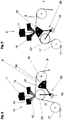
- FIGS. 5 and 6 a further second station 11 for the observation of a material web 4 is shown.
- This station has an abutment system 20 with two alternative abutments 22 and 32.
- FIG. 5 serves a white roller 22 as an object or measurement background.
- the arrow 19 indicates that the system 20 in the context of a Pivoting movement can also activate the counter 32, as the in FIG. 6 is shown.
- the roller 22 serves merely as a guide roller, while the counter-layer 32 guides the web on the opposite side of the sensor.
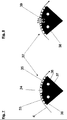
- FIGS. 7 and 8 show two embodiments of this counter-surface 32.
- the web 4 facing surface of the counter-32 has a convex profile.
- the web 4 first sweeps over the first surface 33 of the backsheet 32.
- This consists of a porous material, preferably of microporous Teflon, which can be produced by a sintering process.
- This material is traversed by a line 38 which introduces compressed air.
- This compressed air flows through the porous material and exits at the first surface 33 of the porous material as indicated by the arrows 36.
- an air cushion is formed, which is represented by the arrows 36 and on which the web 4 floats.
- the web In its transport direction z, the web then enters the area of the mirror 34, which can replace a backlight 18, 39.
- the measure of using a mirror 34 as the measurement background has proven to be so advantageous that this measure also brings advantages independent of the remaining structure of the measuring station and is worth protecting.
- the mirror 34 is followed by the second surface 35 of the counter-layer 32, which is mirror-inverted to the first surface 33 of the counter-layer 32.
- the counter-surface 32 has a pressure-resistant housing 37 on the side facing away from the web 4, which prevents leakage of compressed air.
- the counter 32 in FIG. 8 has in place of the mirror 34 via a backlight 39 and otherwise has the same structure as the counter-32 in FIG. 7 ,
- the FIG. 9 shows a station 41, which the functional components of the station 11 from FIG. 5 with the functional components of the station 1 off FIG. 2 united together.
- this arrangement in a station brings with it further advantages for the quality of the measurement.
- the use of the blowing air nozzles 6, 7 also leads to a cleaning of the web 4 and the optical elements of the web observation station.
Landscapes
- Physics & Mathematics (AREA)
- Spectroscopy & Molecular Physics (AREA)
- General Physics & Mathematics (AREA)
- Engineering & Computer Science (AREA)
- Quality & Reliability (AREA)
- Controlling Sheets Or Webs (AREA)
- Inking, Control Or Cleaning Of Printing Machines (AREA)
Claims (10)
- Machine d'impression de bandes de matériau (4),- comportant une station (1, 11, 41) pour l'observation de la bande de matériau imprimé (4),- dans laquelle la station (1, 11, 41) d'observation de la bande de matériau (4) comprend un capteur pour l'observation de la bande de matériau (4) et au moins un support complémentaire (2, 12, 32) pour guider la bande (4), dans laquelle l'au moins un support complémentaire (2, 12, 32) se trouve sur le côté de la bande qui est opposé au capteur (3, 13),- et dans laquelle la surface du support complémentaire qui est tournée vers la bande de matériau est constituée au moins en partie d'un matériau poreux ou perforé qui est traversé par de l'air sous pression, caractérisée en ce que la surface du support complémentaire qui est tournée vers la bande de matériau (4) présente un miroir (34) et/ou un rétroéclairage (18, 39).
- Machine selon la revendication 1,
caractérisée en ce que la surface du support complémentaire (2, 12, 32) qui est tournée vers la bande de matériau (4) est constituée au moins en partie de Téflon microporeux. - Machine selon l'une quelconque des revendications précédentes,
caractérisée en ce que la station (1, 11, 41) est munie, en plus du support complémentaire (2, 12, 32), d'un rouleau blanc (22) au moyen duquel la bande de matériau (4) peut être guidée dans la zone de fonctionnement du capteur. - Machine selon la revendication précédente,
caractérisée en ce que la bande de matériau peut être guidée alternativement dans la zone de fonctionnement du capteur (3, 13) à l'aide du rouleau blanc (22) et du support complémentaire (32). - Machine selon l'une quelconque des revendications précédentes,
caractérisée en ce que le rouleau blanc (22) peut être écarté de la bande de matériau (4). - Machine selon l'une quelconque des revendications précédentes,
caractérisée en ce que le support complémentaire (32) est immobile par rapport à la bande de matériau (4). - Machine selon l'une quelconque des revendications précédentes,
caractérisée en ce que la surface du support complémentaire (32) immobile qui est tournée vers la bande de matériau (4) dans la direction de déplacement (z) de la bande en amont et/ou en aval du miroir (34) et/ou du rétroéclairage (39) est constituée d'un matériau poreux ou perforé. - Machine selon l'une quelconque des revendications précédentes,
caractérisée par au moins deux autres dispositifs d'éclairage (14, 15) à l'aide desquels la zone d'observation du capteur (3, 13) peut être éclairée depuis le côté tourné vers le capteur. - Machine selon l'une quelconque des revendications précédentes,
caractérisée en ce que la surface du support complémentaire (32) qui est tournée vers la bande de matériau (4) est réalisée de manière à être convexe en section transversale. - Procédé pour l'impression de bandes de matériau (4),- dans lequel la bande de matériau (4) est guidée à travers une station (1, 11, 41) pour l'observation de la bande de matériau imprimée (4),- dans laquelle (1, 11, 41) la bande de matériau (4) est observée au moyen d'un capteur destiné à l'observation de la bande de matériau (4), pendant que la bande de matériau (4) est guidée par au moins un support complémentaire (2, 12, 32) destiné au guidage de la bande (4), dans lequel l'au moins un support complémentaire se trouve sur le côté de la bande de matériau (4) qui est opposé au capteur (3, 13),- et dans lequel la surface du support complémentaire (2, 12, 32) qui est tournée vers la bande de matériau (4) est constituée au moins en partie d'un matériau poreux ou perforé qui est traversé par de l'air sous pression,caractérisé en ce que la surface du support complémentaire qui est tournée vers la bande de matériau (4) présente un miroir (34) et/ou un rétroéclairage (18, 39), dans lequel la bande de matériau (4) passe devant le miroir et/ou le rétroéclairage pendant que le capteur (3, 13) observe la bande de matériau (4).
Applications Claiming Priority (2)
| Application Number | Priority Date | Filing Date | Title |
|---|---|---|---|
| DE102011110796 | 2011-08-22 | ||
| PCT/EP2012/066084 WO2013026791A1 (fr) | 2011-08-22 | 2012-08-17 | Machine et procédé d'impression de bandes d'impression |
Publications (2)
| Publication Number | Publication Date |
|---|---|
| EP2748004A1 EP2748004A1 (fr) | 2014-07-02 |
| EP2748004B1 true EP2748004B1 (fr) | 2017-01-04 |
Family
ID=46690521
Family Applications (1)
| Application Number | Title | Priority Date | Filing Date |
|---|---|---|---|
| EP12748224.8A Active EP2748004B1 (fr) | 2011-08-22 | 2012-08-17 | Machine et procédé d'impression de bandes d'impression |
Country Status (3)
| Country | Link |
|---|---|
| US (1) | US20140208970A1 (fr) |
| EP (1) | EP2748004B1 (fr) |
| WO (1) | WO2013026791A1 (fr) |
Families Citing this family (5)
| Publication number | Priority date | Publication date | Assignee | Title |
|---|---|---|---|---|
| IL216903A (en) * | 2010-12-10 | 2016-09-29 | Advanced Vision Tech (A V T ) Ltd | Conveyor facility with imaging background surface |
| WO2013026792A1 (fr) * | 2011-08-22 | 2013-02-28 | Windmöller & Hölscher Kg | Machine et procédé d'impression de bandes de matériau |
| JP2017019110A (ja) * | 2015-07-07 | 2017-01-26 | 大日本印刷株式会社 | エアー吹付機構、エアー吹付機構付き照明装置 |
| CN110177697B (zh) | 2017-03-28 | 2021-08-27 | 惠普发展公司,有限责任合伙企业 | 进给打印介质和打印机 |
| JP7604150B2 (ja) * | 2020-09-18 | 2024-12-23 | 株式会社Screenホールディングス | 検査装置及びそれを備えたインクジェット印刷装置 |
Family Cites Families (25)
| Publication number | Priority date | Publication date | Assignee | Title |
|---|---|---|---|---|
| US3942230A (en) * | 1974-03-05 | 1976-03-09 | Plasma Coatings, Inc. | Composite metallic roll with release surface and method of making same |
| US4967663A (en) * | 1988-10-24 | 1990-11-06 | Coors Porcelain Company | Unengraved metering roll of porous ceramic |
| IT1269506B (it) * | 1994-02-04 | 1997-04-01 | De La Rue Giori Sa | Impianto di controllo di qualita' di fogli stampati in particolare di carte-valore |
| US5774225A (en) * | 1996-03-27 | 1998-06-30 | Advanced Vision Technology, Ltd. | System and method for color measurement and control on-press during printing |
| DE19613084A1 (de) * | 1996-04-02 | 1997-10-09 | Koenig & Bauer Albert Ag | Saugkasten zum Führen von Bogen |
| US5809885A (en) * | 1996-09-09 | 1998-09-22 | Druckmaschinenwerk Planeta | Blower for printing presses for assisting in the guidance of sheets |
| US6328440B1 (en) * | 2000-01-07 | 2001-12-11 | Hewlett-Packard Company | Buckling control for a heated belt-type media support of a printer |
| US20030035870A1 (en) * | 2000-01-07 | 2003-02-20 | E. Michael Ackley, Jr. | Method to print multicolor images on edible pieces |
| CH694160A5 (fr) * | 2000-05-11 | 2004-08-13 | Bobst Sa | Dispositif de gestion des défauts d'impression détectés au sein d'une machine d'impression. |
| DE10128833B4 (de) * | 2001-06-15 | 2006-11-02 | Koenig & Bauer Ag | Qualitätskontrollvorrichtung |
| FI114337B (fi) * | 2001-07-03 | 2004-09-30 | Metso Automation Oy | Menetelmä ja mittalaite liikkuvan rainan ainakin yhden ominaisuuden mittaamiseksi |
| US7105848B2 (en) * | 2002-04-15 | 2006-09-12 | Wintriss Engineering Corporation | Dual level out-of-focus light source for amplification of defects on a surface |
| DE10339651B3 (de) * | 2003-08-28 | 2005-03-24 | Man Roland Druckmaschinen Ag | Verfahren und Vorrichtung zur Ermittlung von Rastertonwerten durch direkte Aufnahme von verschiedenen drucktechnischen Substraten |
| US7354147B2 (en) * | 2003-11-04 | 2008-04-08 | Hewlett-Packard Development Company, L.P. | Platen having channels and method for the same |
| WO2005072265A2 (fr) * | 2004-01-22 | 2005-08-11 | Wintriss Engineering Corporation | Systeme d'eclairage pour inspection de matiere |
| DE102004007374B3 (de) | 2004-02-16 | 2005-08-04 | Koenig & Bauer Ag | Vorrichtungen zum berührunglosen Abtasten einer Bahn |
| US20070139703A1 (en) * | 2005-12-19 | 2007-06-21 | Glory Ltd. | Print inspecting apparatus |
| FI119260B (fi) * | 2006-03-10 | 2008-09-15 | Metso Automation Oy | Menetelmä mittauslaitteiston kalibroimiseksi ja mittauslaitteisto |
| DE102007025910B4 (de) * | 2007-06-01 | 2013-08-29 | Windmöller & Hölscher Kg | Hintergrundbeleuchtung |
| IL216903A (en) * | 2010-12-10 | 2016-09-29 | Advanced Vision Tech (A V T ) Ltd | Conveyor facility with imaging background surface |
| CN103502015B (zh) * | 2011-04-27 | 2016-07-06 | 柯尼卡美能达株式会社 | 喷墨记录装置 |
| WO2013026792A1 (fr) * | 2011-08-22 | 2013-02-28 | Windmöller & Hölscher Kg | Machine et procédé d'impression de bandes de matériau |
| JP6049177B2 (ja) * | 2012-09-19 | 2016-12-21 | 株式会社小森コーポレーション | シート状物の検査装置 |
| JP5971800B2 (ja) * | 2012-09-19 | 2016-08-17 | 株式会社小森コーポレーション | シート状物の検査装置 |
| JP6026194B2 (ja) * | 2012-09-21 | 2016-11-16 | 株式会社東芝 | 紙葉類の再検査装置、紙葉類検査システム、及び紙葉類検査方法 |
-
2012
- 2012-08-17 WO PCT/EP2012/066084 patent/WO2013026791A1/fr not_active Ceased
- 2012-08-17 US US14/238,530 patent/US20140208970A1/en not_active Abandoned
- 2012-08-17 EP EP12748224.8A patent/EP2748004B1/fr active Active
Non-Patent Citations (1)
| Title |
|---|
| None * |
Also Published As
| Publication number | Publication date |
|---|---|
| EP2748004A1 (fr) | 2014-07-02 |
| WO2013026791A1 (fr) | 2013-02-28 |
| US20140208970A1 (en) | 2014-07-31 |
Similar Documents
| Publication | Publication Date | Title |
|---|---|---|
| EP2748005B1 (fr) | Machine et procédé d'impression de bandes de matériau | |
| EP2748004B1 (fr) | Machine et procédé d'impression de bandes d'impression | |
| DE10057036C2 (de) | Inspektionssystem für Flachgläser in der Displayfertigung | |
| EP1744883A1 (fr) | Dispositif de controle en ligne de la qualite d'impression dans une presse offset alimentee par feuilles | |
| DE102007043581B4 (de) | Optische Überwachungsvorrichtung für Rundlaufpressen | |
| DE102007003224A1 (de) | Bearbeitungslinie für plattenartige Elemente, insbesondere Solarzellen, und Verfahren zum Bearbeiten von plattenartigen Elementen | |
| EP4043218B1 (fr) | Machine d'impression dotée d'un dispositif de transport de support à imprimer et d'une caméra | |
| DE2906037A1 (de) | Vorrichtung zum feststellen von rissen bzw. bruechen bzw. des endes eines streifens | |
| DE102006057215A1 (de) | Vorrichtung an einer Spinnereivorbereitungsanlage zum Erkennen von Fremdstoffen in Fasergut | |
| DE102005018855A1 (de) | Vorrichtung zur Inspektion von Druckererzeugnissen | |
| EP2422972B1 (fr) | Dispositif d'inspection pivotant | |
| DE102015007325A1 (de) | Transportsystem für einen Tintenstrahldrucker | |
| EP2546177A1 (fr) | Procédé et dispositif destinés au contrôle de la qualité de produits d'impression plats | |
| WO2014183913A1 (fr) | Dispositif de mesure de couleur, en particulier pour presse à imprimer | |
| EP0759330A2 (fr) | Dispositif pour l'établissement d'une connexion de fluide entre un raccord de fluide fixe et un conteneur en mouvement | |
| EP1935646A2 (fr) | Unité de mesure pour la saisie continue et automatique de données colorées | |
| AT410980B (de) | Partikelsonde, messsystem sowie verfahren zur bestimmung der staubbeladung eines bahnförmigen gegenstandes | |
| DE102007049192B4 (de) | Vorrichtung und Verfahren zum Transport einer bedruckten Materialbahn | |
| DE102010003046A1 (de) | Vorrichtung und Verfahren zum Führen eines Bogens unter Inline-Messsystemen | |
| EP3718728B1 (fr) | Système de surveillance de bande et procédé de surveillance de bande | |
| DE102018126049A1 (de) | Anlage für eine tafelförmiges Substrat verarbeitende Maschine, Verfahren zum Einrichten und Verfahren zum Betreiben einer Anlage | |
| DE10356107B4 (de) | Bogenanleger mit Vorderkantentrennung und berührungsloser Stapelabtastung | |
| EP2674747B1 (fr) | Procédé et dispositif pour la mesure de couleur sur une image imprimée sur une bande de matériau continue | |
| DE102007051582B4 (de) | Verfahren zum Betreiben einer Vorrichtung zum optischen Messen eines Druckbogens | |
| DE3716389C2 (fr) |
Legal Events
| Date | Code | Title | Description |
|---|---|---|---|
| PUAI | Public reference made under article 153(3) epc to a published international application that has entered the european phase |
Free format text: ORIGINAL CODE: 0009012 |
|
| 17P | Request for examination filed |
Effective date: 20140324 |
|
| AK | Designated contracting states |
Kind code of ref document: A1 Designated state(s): AL AT BE BG CH CY CZ DE DK EE ES FI FR GB GR HR HU IE IS IT LI LT LU LV MC MK MT NL NO PL PT RO RS SE SI SK SM TR |
|
| DAX | Request for extension of the european patent (deleted) | ||
| GRAP | Despatch of communication of intention to grant a patent |
Free format text: ORIGINAL CODE: EPIDOSNIGR1 |
|
| INTG | Intention to grant announced |
Effective date: 20160801 |
|
| GRAS | Grant fee paid |
Free format text: ORIGINAL CODE: EPIDOSNIGR3 |
|
| GRAA | (expected) grant |
Free format text: ORIGINAL CODE: 0009210 |
|
| AK | Designated contracting states |
Kind code of ref document: B1 Designated state(s): AL AT BE BG CH CY CZ DE DK EE ES FI FR GB GR HR HU IE IS IT LI LT LU LV MC MK MT NL NO PL PT RO RS SE SI SK SM TR |
|
| REG | Reference to a national code |
Ref country code: GB Ref legal event code: FG4D Free format text: NOT ENGLISH |
|
| REG | Reference to a national code |
Ref country code: CH Ref legal event code: EP |
|
| REG | Reference to a national code |
Ref country code: AT Ref legal event code: REF Ref document number: 858836 Country of ref document: AT Kind code of ref document: T Effective date: 20170115 |
|
| REG | Reference to a national code |
Ref country code: IE Ref legal event code: FG4D Free format text: LANGUAGE OF EP DOCUMENT: GERMAN |
|
| REG | Reference to a national code |
Ref country code: DE Ref legal event code: R096 Ref document number: 502012009224 Country of ref document: DE |
|
| REG | Reference to a national code |
Ref country code: LT Ref legal event code: MG4D Ref country code: NL Ref legal event code: MP Effective date: 20170104 |
|
| PG25 | Lapsed in a contracting state [announced via postgrant information from national office to epo] |
Ref country code: NL Free format text: LAPSE BECAUSE OF FAILURE TO SUBMIT A TRANSLATION OF THE DESCRIPTION OR TO PAY THE FEE WITHIN THE PRESCRIBED TIME-LIMIT Effective date: 20170104 |
|
| PG25 | Lapsed in a contracting state [announced via postgrant information from national office to epo] |
Ref country code: HR Free format text: LAPSE BECAUSE OF FAILURE TO SUBMIT A TRANSLATION OF THE DESCRIPTION OR TO PAY THE FEE WITHIN THE PRESCRIBED TIME-LIMIT Effective date: 20170104 Ref country code: NO Free format text: LAPSE BECAUSE OF FAILURE TO SUBMIT A TRANSLATION OF THE DESCRIPTION OR TO PAY THE FEE WITHIN THE PRESCRIBED TIME-LIMIT Effective date: 20170404 Ref country code: LT Free format text: LAPSE BECAUSE OF FAILURE TO SUBMIT A TRANSLATION OF THE DESCRIPTION OR TO PAY THE FEE WITHIN THE PRESCRIBED TIME-LIMIT Effective date: 20170104 Ref country code: FI Free format text: LAPSE BECAUSE OF FAILURE TO SUBMIT A TRANSLATION OF THE DESCRIPTION OR TO PAY THE FEE WITHIN THE PRESCRIBED TIME-LIMIT Effective date: 20170104 Ref country code: IS Free format text: LAPSE BECAUSE OF FAILURE TO SUBMIT A TRANSLATION OF THE DESCRIPTION OR TO PAY THE FEE WITHIN THE PRESCRIBED TIME-LIMIT Effective date: 20170504 Ref country code: GR Free format text: LAPSE BECAUSE OF FAILURE TO SUBMIT A TRANSLATION OF THE DESCRIPTION OR TO PAY THE FEE WITHIN THE PRESCRIBED TIME-LIMIT Effective date: 20170405 |
|
| PG25 | Lapsed in a contracting state [announced via postgrant information from national office to epo] |
Ref country code: PT Free format text: LAPSE BECAUSE OF FAILURE TO SUBMIT A TRANSLATION OF THE DESCRIPTION OR TO PAY THE FEE WITHIN THE PRESCRIBED TIME-LIMIT Effective date: 20170504 Ref country code: SE Free format text: LAPSE BECAUSE OF FAILURE TO SUBMIT A TRANSLATION OF THE DESCRIPTION OR TO PAY THE FEE WITHIN THE PRESCRIBED TIME-LIMIT Effective date: 20170104 Ref country code: PL Free format text: LAPSE BECAUSE OF FAILURE TO SUBMIT A TRANSLATION OF THE DESCRIPTION OR TO PAY THE FEE WITHIN THE PRESCRIBED TIME-LIMIT Effective date: 20170104 Ref country code: ES Free format text: LAPSE BECAUSE OF FAILURE TO SUBMIT A TRANSLATION OF THE DESCRIPTION OR TO PAY THE FEE WITHIN THE PRESCRIBED TIME-LIMIT Effective date: 20170104 Ref country code: BG Free format text: LAPSE BECAUSE OF FAILURE TO SUBMIT A TRANSLATION OF THE DESCRIPTION OR TO PAY THE FEE WITHIN THE PRESCRIBED TIME-LIMIT Effective date: 20170404 Ref country code: RS Free format text: LAPSE BECAUSE OF FAILURE TO SUBMIT A TRANSLATION OF THE DESCRIPTION OR TO PAY THE FEE WITHIN THE PRESCRIBED TIME-LIMIT Effective date: 20170104 Ref country code: LV Free format text: LAPSE BECAUSE OF FAILURE TO SUBMIT A TRANSLATION OF THE DESCRIPTION OR TO PAY THE FEE WITHIN THE PRESCRIBED TIME-LIMIT Effective date: 20170104 |
|
| REG | Reference to a national code |
Ref country code: DE Ref legal event code: R097 Ref document number: 502012009224 Country of ref document: DE |
|
| PG25 | Lapsed in a contracting state [announced via postgrant information from national office to epo] |
Ref country code: CZ Free format text: LAPSE BECAUSE OF FAILURE TO SUBMIT A TRANSLATION OF THE DESCRIPTION OR TO PAY THE FEE WITHIN THE PRESCRIBED TIME-LIMIT Effective date: 20170104 Ref country code: SK Free format text: LAPSE BECAUSE OF FAILURE TO SUBMIT A TRANSLATION OF THE DESCRIPTION OR TO PAY THE FEE WITHIN THE PRESCRIBED TIME-LIMIT Effective date: 20170104 Ref country code: IT Free format text: LAPSE BECAUSE OF FAILURE TO SUBMIT A TRANSLATION OF THE DESCRIPTION OR TO PAY THE FEE WITHIN THE PRESCRIBED TIME-LIMIT Effective date: 20170104 Ref country code: RO Free format text: LAPSE BECAUSE OF FAILURE TO SUBMIT A TRANSLATION OF THE DESCRIPTION OR TO PAY THE FEE WITHIN THE PRESCRIBED TIME-LIMIT Effective date: 20170104 Ref country code: EE Free format text: LAPSE BECAUSE OF FAILURE TO SUBMIT A TRANSLATION OF THE DESCRIPTION OR TO PAY THE FEE WITHIN THE PRESCRIBED TIME-LIMIT Effective date: 20170104 |
|
| PLBE | No opposition filed within time limit |
Free format text: ORIGINAL CODE: 0009261 |
|
| STAA | Information on the status of an ep patent application or granted ep patent |
Free format text: STATUS: NO OPPOSITION FILED WITHIN TIME LIMIT |
|
| PG25 | Lapsed in a contracting state [announced via postgrant information from national office to epo] |
Ref country code: SM Free format text: LAPSE BECAUSE OF FAILURE TO SUBMIT A TRANSLATION OF THE DESCRIPTION OR TO PAY THE FEE WITHIN THE PRESCRIBED TIME-LIMIT Effective date: 20170104 Ref country code: DK Free format text: LAPSE BECAUSE OF FAILURE TO SUBMIT A TRANSLATION OF THE DESCRIPTION OR TO PAY THE FEE WITHIN THE PRESCRIBED TIME-LIMIT Effective date: 20170104 |
|
| 26N | No opposition filed |
Effective date: 20171005 |
|
| PG25 | Lapsed in a contracting state [announced via postgrant information from national office to epo] |
Ref country code: SI Free format text: LAPSE BECAUSE OF FAILURE TO SUBMIT A TRANSLATION OF THE DESCRIPTION OR TO PAY THE FEE WITHIN THE PRESCRIBED TIME-LIMIT Effective date: 20170104 |
|
| REG | Reference to a national code |
Ref country code: CH Ref legal event code: PL |
|
| PG25 | Lapsed in a contracting state [announced via postgrant information from national office to epo] |
Ref country code: MC Free format text: LAPSE BECAUSE OF FAILURE TO SUBMIT A TRANSLATION OF THE DESCRIPTION OR TO PAY THE FEE WITHIN THE PRESCRIBED TIME-LIMIT Effective date: 20170104 |
|
| GBPC | Gb: european patent ceased through non-payment of renewal fee |
Effective date: 20170817 |
|
| PG25 | Lapsed in a contracting state [announced via postgrant information from national office to epo] |
Ref country code: LI Free format text: LAPSE BECAUSE OF NON-PAYMENT OF DUE FEES Effective date: 20170831 Ref country code: CH Free format text: LAPSE BECAUSE OF NON-PAYMENT OF DUE FEES Effective date: 20170831 |
|
| REG | Reference to a national code |
Ref country code: FR Ref legal event code: ST Effective date: 20180430 |
|
| REG | Reference to a national code |
Ref country code: IE Ref legal event code: MM4A |
|
| REG | Reference to a national code |
Ref country code: BE Ref legal event code: MM Effective date: 20170831 |
|
| PG25 | Lapsed in a contracting state [announced via postgrant information from national office to epo] |
Ref country code: LU Free format text: LAPSE BECAUSE OF NON-PAYMENT OF DUE FEES Effective date: 20170817 |
|
| PG25 | Lapsed in a contracting state [announced via postgrant information from national office to epo] |
Ref country code: GB Free format text: LAPSE BECAUSE OF NON-PAYMENT OF DUE FEES Effective date: 20170817 Ref country code: IE Free format text: LAPSE BECAUSE OF NON-PAYMENT OF DUE FEES Effective date: 20170817 |
|
| PG25 | Lapsed in a contracting state [announced via postgrant information from national office to epo] |
Ref country code: FR Free format text: LAPSE BECAUSE OF NON-PAYMENT OF DUE FEES Effective date: 20170831 Ref country code: BE Free format text: LAPSE BECAUSE OF NON-PAYMENT OF DUE FEES Effective date: 20170831 |
|
| PG25 | Lapsed in a contracting state [announced via postgrant information from national office to epo] |
Ref country code: MT Free format text: LAPSE BECAUSE OF FAILURE TO SUBMIT A TRANSLATION OF THE DESCRIPTION OR TO PAY THE FEE WITHIN THE PRESCRIBED TIME-LIMIT Effective date: 20170104 |
|
| REG | Reference to a national code |
Ref country code: AT Ref legal event code: MM01 Ref document number: 858836 Country of ref document: AT Kind code of ref document: T Effective date: 20170817 |
|
| PG25 | Lapsed in a contracting state [announced via postgrant information from national office to epo] |
Ref country code: AT Free format text: LAPSE BECAUSE OF NON-PAYMENT OF DUE FEES Effective date: 20170817 |
|
| PG25 | Lapsed in a contracting state [announced via postgrant information from national office to epo] |
Ref country code: HU Free format text: LAPSE BECAUSE OF FAILURE TO SUBMIT A TRANSLATION OF THE DESCRIPTION OR TO PAY THE FEE WITHIN THE PRESCRIBED TIME-LIMIT; INVALID AB INITIO Effective date: 20120817 |
|
| PG25 | Lapsed in a contracting state [announced via postgrant information from national office to epo] |
Ref country code: CY Free format text: LAPSE BECAUSE OF NON-PAYMENT OF DUE FEES Effective date: 20170104 |
|
| PG25 | Lapsed in a contracting state [announced via postgrant information from national office to epo] |
Ref country code: MK Free format text: LAPSE BECAUSE OF FAILURE TO SUBMIT A TRANSLATION OF THE DESCRIPTION OR TO PAY THE FEE WITHIN THE PRESCRIBED TIME-LIMIT Effective date: 20170104 |
|
| PG25 | Lapsed in a contracting state [announced via postgrant information from national office to epo] |
Ref country code: TR Free format text: LAPSE BECAUSE OF FAILURE TO SUBMIT A TRANSLATION OF THE DESCRIPTION OR TO PAY THE FEE WITHIN THE PRESCRIBED TIME-LIMIT Effective date: 20170104 |
|
| PG25 | Lapsed in a contracting state [announced via postgrant information from national office to epo] |
Ref country code: AL Free format text: LAPSE BECAUSE OF FAILURE TO SUBMIT A TRANSLATION OF THE DESCRIPTION OR TO PAY THE FEE WITHIN THE PRESCRIBED TIME-LIMIT Effective date: 20170104 |
|
| PGFP | Annual fee paid to national office [announced via postgrant information from national office to epo] |
Ref country code: DE Payment date: 20250831 Year of fee payment: 14 |