EP2748040B1 - Fahrwerk - Google Patents
Fahrwerk Download PDFInfo
- Publication number
- EP2748040B1 EP2748040B1 EP11799482.2A EP11799482A EP2748040B1 EP 2748040 B1 EP2748040 B1 EP 2748040B1 EP 11799482 A EP11799482 A EP 11799482A EP 2748040 B1 EP2748040 B1 EP 2748040B1
- Authority
- EP
- European Patent Office
- Prior art keywords
- bushing
- outer bushing
- drive
- gear ring
- gear
- Prior art date
- Legal status (The legal status is an assumption and is not a legal conclusion. Google has not performed a legal analysis and makes no representation as to the accuracy of the status listed.)
- Active
Links
Images


Classifications
-
- B—PERFORMING OPERATIONS; TRANSPORTING
- B60—VEHICLES IN GENERAL
- B60S—SERVICING, CLEANING, REPAIRING, SUPPORTING, LIFTING, OR MANOEUVRING OF VEHICLES, NOT OTHERWISE PROVIDED FOR
- B60S9/00—Ground-engaging vehicle fittings for supporting, lifting, or manoeuvring the vehicle, wholly or in part, e.g. built-in jacks
- B60S9/02—Ground-engaging vehicle fittings for supporting, lifting, or manoeuvring the vehicle, wholly or in part, e.g. built-in jacks for only lifting or supporting
- B60S9/04—Ground-engaging vehicle fittings for supporting, lifting, or manoeuvring the vehicle, wholly or in part, e.g. built-in jacks for only lifting or supporting mechanically
- B60S9/06—Ground-engaging vehicle fittings for supporting, lifting, or manoeuvring the vehicle, wholly or in part, e.g. built-in jacks for only lifting or supporting mechanically of screw-and-nut type
- B60S9/08—Ground-engaging vehicle fittings for supporting, lifting, or manoeuvring the vehicle, wholly or in part, e.g. built-in jacks for only lifting or supporting mechanically of screw-and-nut type the screw axis being substantially vertical
Definitions
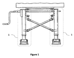
- This invention relates to the jacks ensuring trailers, truck trailers and tractor trailers to stand firmly and functionally in park without a tractor unit.
- Trailer parking legs are used in order to ensure trailers, truck trailers and tractor trailers to stand independently in park without a tractor unit.
- Two parking legs are fixed on the right and left sides of the wheelless front parts of vehicles such as trailer, tractor trailer.
- the fact that the part, which is located in the height adjusting mechanisms of parking legs in the left and right hands and called as nut, has different geometry for both legs is one of the most important problems of parking legs produced today.
- the reason for this problem is the fact that the height adjusting shaft passing through the nut is not produced equiaxially with the body of parking leg.
- the shaft used in the left parking leg of the vehicle is located on the right side of parking leg, and the shaft used in the right parking leg of the vehicle is located on the left side of parking leg.
- a telescopic support device for trailers is mentioned.
- the device includes an outer tube, a first inner tube that can stretch downward inside the outer tube and at least one telescopic support leg consisting of one fixing plate for fixing the support bracket to the object to be supported.
- it is produced with girders from a light metal like aluminum alloy as monolith with the outer tube fixing plate by extrusion method.
- the objective of this invention is to produce a parking leg ensuring vehicles such as trailers, truck trailers and tractor trailers to stand functional and in balance independently of a tractor unit.
- Another objective of this invention is to produce a parking leg which is equiaxial with height adjusting shaft, outer bushing and inner bushing.
- Another object of this invention is to produce a lightened and strengthened parking leg.
- Another object of this invention is to produce a cost-efficient parking leg.
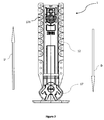
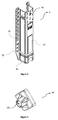
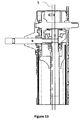
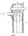
- Parking leg (1) subjecting to the invention which ensures trailers, truck trailers and tractor trailers to stand firmly and functionally in park without a tractor unit includes;
- Inner bushing (2) constitutes the part of the trailer parking leg (1) subjecting to the invention that is fixed on the ground. Other parts of the parking leg (1) are connected to the inner bushing (2) directly or indirectly.
- the inner bushing (2) is produced from a sheet metal made from any metal or metal alloy for the preferred application of the invention.
- stamping press (13) is exerted to the bushing. Usage of heavy and costly shaped tubes is prevented by producing inner bushing from sheet metal.
- the outer bushing (3) circles the inner bushing (2) and preferably has a tetragonal structure as the inner bushing (2).
- the outer bushing (3) can move up and down over the inner bushing (2) while the height of the parking leg (1) is adjusted.
- the outer bushing (3) is produced from a sheet metal made from any metal or metal alloy for the preferred application of the invention.
- stamping press (13) is exerted to the bushing.
- the drive shaft (4) is the part to which the necessary drive is given for the height adjustment of the parking leg (1). During the upward and downward movement of the outer bushing (3), the drive shaft (4) also moves together with the outer bushing (3). The drive shaft (4) can move inside or outside of the outer bushing (3).
- the pinion gear (5) is fixed to the drive shaft (4) as equiaxial with the drive shaft (4).
- the pinion gear (5) gets in contact with the big gear ring (6).
- the pinion gear (5) starts to rotate the big gear ring (6) with the drive it gets from the drive shaft (4).
- the pinion gear (5) contacts with the gears on the inner surface of the drive gear (19).
- the trailer parking leg can be used in preferred speed by moving the drive shaft (4) in the direction of arrow C or arrow B.
- the big gear ring (6) When the big gear ring (6) is pushed in the direction of arrow C, it contacts with the pinion gear (5).
- the big gear ring (6) is fixed to the support shaft (8) which passes through its center equiaxially.
- the big gear ring (6) starts to rotate with the drive it gets from the pinion gear (5) and rotates the support shaft (8) in the same axis.
- the vertical cone gear (7) is fixed to the support shaft (8) equiaxially with the support shaft (8).
- the vertical cone gear (7) also starts to rotate in the same axis with the support shaft (8).
- the vertical cone gear (7) is in contact with the horizontal cone gear (9).
- the movement of the vertical cone gear (7) enables the horizontal cone gear (9) which is fixed in the outer bushing in the same axis with inner bushing (2) and outer bushing (3) to rotate around its own axis.
- the vertical cone gear (7) and the horizontal cone gear (9) is located inside the outer bushing (3).
- the horizontal cone gear (9) is fixed to the height adjusting shaft (10) which is placed in the same axis with the horizontal cone gear (9). By the movement of the horizontal cone gear (9), the height adjusting gear starts to rotate in the same axis.
- the screw pitches on the exterior surface of the height adjusting shaft (10) are in cooperation with the screw pitches on the threaded hole (111) located on the nut.
- the pinion gear (5) which is fixed on the drive shaft (4) enables the drive gear (19) to rotate in the same axis and direction.
- the drive gear (19) is placed equiaxially with the drive shaft (4) on the part of drive shaft (4) out of the outer bushing (3) and in such a way that it can rotate independently of the drive shaft.
- the drive gear (19) which is placed outside of the outer bushing (3) is preferably covered by transmission cover (18).
- the small gear ring (20) is fixed to the part of support shaft (8) that is removed from the outer bushing (3) through the assembly slot (14).
- the small gear ring (20) is in contact with the drive gear (19) and transfers the drive it gets from the drive gear (19) to the support shaft (8) and the big gear ring (6).
- the small gear ring (20) is covered with the transmission cover for the preferred application of the invention.
- the height adjusting shaft (10) By placing the small gear ring (20) and drive gear (19) outside of the outer bushing (3), a wide area is provided inside the inner bushing (2) and the height adjusting shaft (10) can be placed in the same axis with the inner bushing (2). By this way, the center of threaded hole (111) through which the height adjusting shaft (10) passes comes up to the symmetry axis (S) of the nut (11) and the inner bushing (2).
- the fact that the small gear ring (20) and drive shaft (4) are placed outside of the outer bushing (3) also facilitates the assembly and maintenance of small gear ring (20) and drive shaft (4).
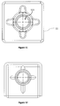
- the connector plate (12) is the part with which the parking leg (1) subjecting to the invention is assembled to vehicles like trailers.
- the connector plate (12) is produced as monolith with the outer bushing (3) for the preferred application of the invention.
- stamping press In order to increase the endurance of outer bushing (3) and inner bushing (2) on the parking leg (1) subjecting to the invention stamping press (13), which can be in different forms, is used to give a shape. By this way, endurance level against deformation has increased; the opportunity of production with lighter materials has arisen, total weight and cost have decreased.
- Profile presses (15) are available under the outer bushing (3) for increasing the endurance level. Bands are not required anymore for this part thanks to the increased endurance level attained by profile pressing (15). By this way the number of the materials decreases, and so do the cost and weight.
- Equiaxial countersinks (16) are placed on the connector plates equiaxially with the screw holes (121). Equiaxial countersinks (16) provide high endurance, a firm structure and easy assembly.
- the assembly slot (14) is a slot opened on the outer bushing (3).
- Small gear ring is placed on the part of support shaft (8) driving off the outer bushing (3), which locates out of the outer bushing (3) through the assembly slot.
- the fact that the small gear ring (20) is placed out of the outer bushing (3) through the assembly slot (14) facilitates maintenance and assembly.
- the drive gear (19) can be placed on the part of the drive shaft (4) out of the outer bushing by the fact that the small gear ring (20) is placed out of the outer bushing (3). By this way, maintenance and assembly of the drive gear (19) can be done easily.
- the transmission cover (18) is placed over the drive gear (19) and small gear ring (20) which locate out of the outer bushing (3), and protect drive gear (19) and small gear ring (20) from outer environment.
- the transmission cover (18) is produced in a way that it can be removed from the outer bushing (3).
- the transmission cover (18) is preferably fixed to the outer bushing with at least one screw. Countersinks are placed equiaxially with the connection axis around the screw holes (which are not shown in figures) used for fixing the transmission cover (18) to the outer bushing (3). By this way, the connection becomes more rigid.
- the endurance level of the transmission cover (18) is increased by applying horizontal, vertical and rotational stamping press.
Landscapes
- Engineering & Computer Science (AREA)
- Mechanical Engineering (AREA)
- General Details Of Gearings (AREA)
Claims (14)
- Eine Parkstütze (1), die es ermöglicht, dass die Anhänger, Lkw-Anhänger und Sattelschlepper ohne ein Zugelement fest und funktionell stehen, aufweisend;- zumindest eine innere Buchse (2),- zumindest eine äußere Buchse (3), die an der äußeren Seite der besagten mindestens einen inneren Buchse (2) angeordnet ist und sich aufwärts (U) und abwärts (D) bewegt,- zumindest einen Getriebedeckel (18), der auf der mindestens einen besagten äußeren Buchse (3)angeordnet ist,- zumindest eine Antriebswelle (4), die zur Achse der mindestens einen besagten inneren Buchse (2) und der zumindest einen besagten äußeren Buchse (3) senkrecht angeordnet ist,- zumindest ein Ritzel (5), das der zumindest einer besagten Antriebswelle (4) befestigt ist, die mit der zumindest einen besagten Antriebswelle (4) äquiaxial ist,- mindestens einen großen Zahnkranz (6),- zumindest ein vertikales Kegelzahnrad (7), das zum zumindest einem besagten großen Zahnkranz (6) befestigt ist, der mit dem zumindest einem besagten Zahnkranz (6) äquiaxial ist,- eine Stützwelle (8), die durch die Zentren des zumindest einen besagten großen Zahnkranzes (6) sowie des zumindest einen besagten Kegelzahnrads (7) hindurchgeführt ist,- zumindest ein horizontales Kegelzahnrad (9), das an einer zur Achse des zumindest einen besagten Kegelzahnrads (7) vertikalen Achse angeordnet ist und mit dem zumindest einen besagten Kegelzahnrad (7) in Kontakt steht,- zumindest eine Höhenjustierwelle (10), die an dem mindestens einen besagten horizontalen Kegelzahnrad (9) befestigt ist,- zumindest einen Schuh (17), der an der zumindest einen besagten inneren Buchse (2) befestigt ist,- zumindest ein Antriebswellenlager (23), welches in der mindestens einen besagten äußeren Buchse angeordnet ist und die zumindest eine besagte Antriebswelle (4) trägt und wodurch die zumindest eine besagte Höhenjustierwelle (10) hindurchgeführt ist,- zumindest eine Nut (11), durch welche die mindestens eine besagte Höhenjustierwelle (10) hindurchgeführt wird und welche in der mindestens einen besagten inneren Buchse (2) platziert ist,- eine Gewindebohrung (111), die auf der zumindest einen besagten Nut (11) angeordnet ist, wobei sie es ermöglicht, dass die zumindest eine besagte Höhenjustierwelle (10) durch die zumindest eine besagte Nut (11) hindurchgeht,- zumindest eine Nut-Halterung (21), die zumindest eine besagte Nut (11) innerhalb der zumindest einen besagten inneren Buchse (2) festhält,- eine Ölwanne (22), die auf dem oberen Teil der Nut (11) angeordnet ist (11),- zumindest ein Antriebsrad (19),- zumindest einen kleinen Zahnkranz (20), der den von dem zumindest einen besagten Antriebsrad (19) kommenden Antrieb zur Stützwelle (8) und zum großen Zahnkranz (6) überträgt,- Konnektor-Platten (12) auf beiden Seiten der zumindest einen besagten äußeren Buchse (3),- Befestigungslöcher (121), die auf den Konnektor-Platten (12) angeordnet sind,- Prägepresse (13), die auf der zumindest einen besagten äußeren Buchse (3) angewandt wird, um die Haltbarkeit der zumindest einen besagten äußeren Buchse (3) zu erhöhen,- zumindest eine Montage-Aussparung (14), die auf der mindestens einen besagten äußeren Buchse (3)platziert ist,- Profilpressen (15), das zu der zumindest einen besagten äußeren Buchse (3) angewandt wird,- äquiaxiale Versenkungen (16) auf den Konnektor-Platten (12),und wobei- eine Höhenjustierwelle (10) äquiaxial mit der zumindest einen besagten inneren Buchse (2) in der zumindest einen besagten inneren Buchse (2) angeordnet ist,- eine Nut (11) eine Gewindebohrung (111) aufweist, deren Mittelpunkt auf einer Symmetrieachse der zumindest einen besagten Nut (11) ist,- die zumindest eine besagte Montage-Aussparung (14) es ermöglicht, dass zumindest eine besagte Antriebswelle (4) und zumindest ein kleiner Zahnkranz außerhalb der zumindest einen besagten äußeren Buchse (3) angeordnet werden, indem es ermöglicht wird, dass die Stützwelle (8) aus zumindest einer besagten äußeren Buchse (3) herausgeführt ist,- zumindest ein besagter kleiner Zahnkranz (20) außerhalb der zumindest einen besagten äußeren Buchse (3) angeordnet wird, um in der zumindest einen besagten inneren Buchse (2) Platz zu machen und Wartungsarbeiten sowie Montage zu erleichtern,- zumindest ein besagtes Antriebsrad (19) außerhalb der zumindest einen besagten äußeren Buchse (3) angeordnet wird, um in der zumindest einen besagten inneren Buchse (2) Platz zu machen und Wartungsarbeiten sowie Montage zu erleichtern,- die zumindest eine besagte innere Buchse (2) im Hinblick auf leichtes Gewicht und niedrige Kosten aus Blech gefertigt ist und deren Haltbarkeits-Niveau durch Prägepresse (13) erhöht ist,- die zumindest eine besagte äußere Buchse (3) im Hinblick auf leichtes Gewicht und niedrige Kosten aus Blech gefertigt ist und deren Haltbarkeits-Niveau durch Prägepresse (13) erhöht ist,
- Eine Parkstütze (1) wie im Anspruch 1, gekennzeichnet durch zumindest eine äußere Buchse (3), welche sich auf der mindestens einen besagten inneren Buchse (2) aufwärts und abwärts bewegen kann.
- Eine Parkstütze (1) wie in einem der vorangegangenen Ansprüche, gekennzeichnet durch mindestens eine besagte Antriebswelle (4), die sich während der Bewegung der mindestens einen besagten äußeren Buchse (3) zusammen mit der äußeren Buchse (3) bewegt.
- Eine Parkstütze (1) wie in einem der vorangegangenen Ansprüche, gekennzeichnet durch mindestens eine besagte Antriebswelle (4), wobei deren ein Ende durch die Montage-Aussparung (14) hindurch aus zumindest einer besagten äußeren Buchse (3) herausgeführt ist.
- Eine Parkstütze (1) wie in einem der vorangegangenen Ansprüche, gekennzeichnet durch Stützwelle (8), wobei deren ein Ende durch die Montage-Aussparung (14) hindurch aus zumindest einer besagten äußeren Buchse (3) herausgeführt ist
- Eine Parkstütze (1) wie in einem der vorangegangenen Ansprüche, gekennzeichnet durch zumindest eine besagte Höhenjustierwelle (10) mit Gewindegängen auf ihrer äußeren Oberfläche.
- Eine Parkstütze (1) wie in einem der vorangegangenen Ansprüche, gekennzeichnet durch zumindest eine besagte Nut (11) mit Gewindegängen auf ihrer inneren Oberfläche.
- Eine Parkstütze (1) wie in einem der vorangegangenen Ansprüche, gekennzeichnet durch mindestens ein besagtes Antriebsrad (19), welches an einem Teil der zumindest einen besagten Antriebswelle (4) befestigt ist, welche durch die Montage-Aussparung (14) aus der zumindest einen besagten äußeren Buchse (3) entnommen werden kann.
- Eine Parkstütze (1) wie in einem der vorangegangenen Ansprüche, gekennzeichnet durch mindestens einen besagten kleinen Zahnkranz, welcher an einem Teil der Stützwelle (8) befestigt ist, welche durch die Montage-Aussparung (14) aus der zumindest einen besagten äußeren Buchse (3) entnommen werden kann.
- Eine Parkstütze (1) wie in einem der vorangegangenen Ansprüche, gekennzeichnet durch besagte Montage-Aussparung (14), die auf der zumindest einen besagten äußeren Buchse (3) angeordnet ist und es ermöglicht, dass die Antriebswelle (19) und der zumindest einen besagten kleinen Zahnkranz (20) außerhalb der mindestens einen besagten äußeren Buchse (3) platziert ist, indem es ermöglicht wird, dass ein Ende der Stützwelle (8) und der Antriebswelle (4) aus der äußeren Buchse (3) herausgeführt ist.
- Eine Parkstütze (1) wie in einem der vorangegangenen Ansprüche, gekennzeichnet durch einen Getriebedeckel (18), welcher auf dem zumindest einen besagten Antriebsrad (19) und dem zumindest einen besagten kleinen Zahnkranz (20) platziert ist, welcher außerhalb der mindestens einen äußeren Buchse (3) angeordnet ist und zumindest ein besagtes Antriebsrad (19) und zumindest einen besagten kleinen Zahnkranz (20) vor der äußeren Umgebung schützt.
- Eine Parkstütze (1) wie im Anspruch 11, gekennzeichnet durch den besagten Getriebedeckel (18), der an dem zumindest einen besagten äußeren Buchse (3) mittels Schrauben eingebaut oder davon demontiert werden kann.
- Eine Parkstütze (1) wie im Anspruch 11 oder 12, gekennzeichnet durch den besagten Getriebedeckel (18) aufweisend Versenkungen, welche um die Befestigungslöcher herum, die zur dessen Montage zu der zumindest einen besagten äußeren Buchse eingesetzt werden, äquiaxial mit der Verbindungsachse sind.
- Eine Parkstütze (1) wie im Anspruch 11 oder 12 oder 13, gekennzeichnet durch den besagten Getriebedeckel (18), dessen Haltbarkeit durch horizontale, vertikale und rotationsmäßige Prägepresse erhöht wird.
Applications Claiming Priority (2)
| Application Number | Priority Date | Filing Date | Title |
|---|---|---|---|
| TR201109286 | 2011-09-21 | ||
| PCT/IB2011/055101 WO2013041917A1 (en) | 2011-09-21 | 2011-11-15 | Landing gear |
Publications (2)
| Publication Number | Publication Date |
|---|---|
| EP2748040A1 EP2748040A1 (de) | 2014-07-02 |
| EP2748040B1 true EP2748040B1 (de) | 2016-03-09 |
Family
ID=45390125
Family Applications (1)
| Application Number | Title | Priority Date | Filing Date |
|---|---|---|---|
| EP11799482.2A Active EP2748040B1 (de) | 2011-09-21 | 2011-11-15 | Fahrwerk |
Country Status (2)
| Country | Link |
|---|---|
| EP (1) | EP2748040B1 (de) |
| WO (1) | WO2013041917A1 (de) |
Family Cites Families (6)
| Publication number | Priority date | Publication date | Assignee | Title |
|---|---|---|---|---|
| DE3902613A1 (de) * | 1989-01-29 | 1990-08-02 | Jost Werke Gmbh | Teleskop-stuetzvorrichtung |
| DE19836635C5 (de) * | 1998-08-13 | 2005-07-14 | Jost-Werke Gmbh & Co. Kg | Vorrichtung zum Abstützen eines Aufliegers eines Sattelschleppers |
| CN1911714B (zh) * | 2002-04-02 | 2010-08-25 | Saf霍兰德公司 | 起落架装置和用于制造起落架装置支架的部件 |
| DE102006035919A1 (de) * | 2006-07-31 | 2008-02-14 | Haacon Hebetechnik Gmbh | Hubeinrichtung |
| WO2009065288A1 (en) * | 2007-11-21 | 2009-05-28 | Guangdong Fuwa Engineering Manufacturing Co., Ltd. | A semi-trailer support loading nut |
| DE202009006892U1 (de) * | 2009-03-16 | 2009-09-03 | Riedl, Reinhold, Dipl.-Ing. | Höhenverstellbare Stütze für Sattelauflieger o.dgl. |
-
2011
- 2011-11-15 EP EP11799482.2A patent/EP2748040B1/de active Active
- 2011-11-15 WO PCT/IB2011/055101 patent/WO2013041917A1/en not_active Ceased
Also Published As
| Publication number | Publication date |
|---|---|
| WO2013041917A1 (en) | 2013-03-28 |
| EP2748040A1 (de) | 2014-07-02 |
Similar Documents
| Publication | Publication Date | Title |
|---|---|---|
| EP3554920B1 (de) | Lenkrad für eine kraftfahrzeuglenkung und lenksäule für ein kraftfahrzeug | |
| DE60106157T2 (de) | Automatische Radmontier- und Demontiervorrichtung und damit ausgestattetes Radmontagegerät | |
| CN113680911B (zh) | 一种新型铝材加工用冲压装置 | |
| CN102272483A (zh) | 包含湿式制动器的传动装置 | |
| EP2455275A2 (de) | Hilfsantrieb | |
| WO2014137792A1 (en) | Dual wind jack | |
| EP1927486A2 (de) | Höhenverstellvorrichtung für Radaufhängungen von Kraftfahrzeugen | |
| WO2014005790A1 (de) | Hebevorrichtung und verfahren zur montage und demontage eines rades mit einer solchen hebevorrichtung | |
| CN1651291A (zh) | 用于半拖车或者类似物的可调节高度的支架 | |
| EP1714858B1 (de) | Hilfsantrieb für einen Fahrzeuganhänger mit einseitig gelagerter Antriebsrolle | |
| EP3504102A1 (de) | Lenkrad zum betätigen einer lenkbewegung eines fahrzeuges | |
| CN108928328A (zh) | 一种道路救援用汽车原地调转装置 | |
| EP2748040A1 (de) | Fahrwerk | |
| CN212598481U (zh) | 一种自动化的轮辋卷圆机 | |
| CN113120067B (zh) | 一种集控方向盘 | |
| US20240059344A1 (en) | Steering device | |
| CN202951795U (zh) | 罐体缩颈机的罐身高低调整装置 | |
| EP2844456B1 (de) | Pulverpresse | |
| CN118926418B (zh) | 一种用于汽车后地板的翻转冲压模具 | |
| EP1857346A3 (de) | Neigbare Lenkvorrichtung mit einem festen Radialgetriebe | |
| CN201553192U (zh) | 汽车转向管柱可调倾角装置 | |
| CN217474568U (zh) | 一种用于铝型材的冲压结构 | |
| CN101092148A (zh) | 汽车转向管柱可调倾角装置 | |
| CN113581576B (zh) | 一种用于医药复合硬片包装的喷码设备 | |
| RU2220090C1 (ru) | Домкрат для автомобиля |
Legal Events
| Date | Code | Title | Description |
|---|---|---|---|
| PUAI | Public reference made under article 153(3) epc to a published international application that has entered the european phase |
Free format text: ORIGINAL CODE: 0009012 |
|
| 17P | Request for examination filed |
Effective date: 20140321 |
|
| AK | Designated contracting states |
Kind code of ref document: A1 Designated state(s): AL AT BE BG CH CY CZ DE DK EE ES FI FR GB GR HR HU IE IS IT LI LT LU LV MC MK MT NL NO PL PT RO RS SE SI SK SM TR |
|
| DAX | Request for extension of the european patent (deleted) | ||
| 17Q | First examination report despatched |
Effective date: 20150217 |
|
| GRAP | Despatch of communication of intention to grant a patent |
Free format text: ORIGINAL CODE: EPIDOSNIGR1 |
|
| INTG | Intention to grant announced |
Effective date: 20151016 |
|
| GRAS | Grant fee paid |
Free format text: ORIGINAL CODE: EPIDOSNIGR3 |
|
| GRAA | (expected) grant |
Free format text: ORIGINAL CODE: 0009210 |
|
| AK | Designated contracting states |
Kind code of ref document: B1 Designated state(s): AL AT BE BG CH CY CZ DE DK EE ES FI FR GB GR HR HU IE IS IT LI LT LU LV MC MK MT NL NO PL PT RO RS SE SI SK SM TR |
|
| REG | Reference to a national code |
Ref country code: GB Ref legal event code: FG4D |
|
| REG | Reference to a national code |
Ref country code: AT Ref legal event code: REF Ref document number: 779235 Country of ref document: AT Kind code of ref document: T Effective date: 20160315 Ref country code: CH Ref legal event code: EP |
|
| REG | Reference to a national code |
Ref country code: IE Ref legal event code: FG4D |
|
| REG | Reference to a national code |
Ref country code: DE Ref legal event code: R096 Ref document number: 602011023882 Country of ref document: DE |
|
| REG | Reference to a national code |
Ref country code: LT Ref legal event code: MG4D |
|
| REG | Reference to a national code |
Ref country code: NL Ref legal event code: MP Effective date: 20160309 |
|
| PG25 | Lapsed in a contracting state [announced via postgrant information from national office to epo] |
Ref country code: FI Free format text: LAPSE BECAUSE OF FAILURE TO SUBMIT A TRANSLATION OF THE DESCRIPTION OR TO PAY THE FEE WITHIN THE PRESCRIBED TIME-LIMIT Effective date: 20160309 Ref country code: GR Free format text: LAPSE BECAUSE OF FAILURE TO SUBMIT A TRANSLATION OF THE DESCRIPTION OR TO PAY THE FEE WITHIN THE PRESCRIBED TIME-LIMIT Effective date: 20160610 Ref country code: ES Free format text: LAPSE BECAUSE OF FAILURE TO SUBMIT A TRANSLATION OF THE DESCRIPTION OR TO PAY THE FEE WITHIN THE PRESCRIBED TIME-LIMIT Effective date: 20160309 Ref country code: HR Free format text: LAPSE BECAUSE OF FAILURE TO SUBMIT A TRANSLATION OF THE DESCRIPTION OR TO PAY THE FEE WITHIN THE PRESCRIBED TIME-LIMIT Effective date: 20160309 Ref country code: NO Free format text: LAPSE BECAUSE OF FAILURE TO SUBMIT A TRANSLATION OF THE DESCRIPTION OR TO PAY THE FEE WITHIN THE PRESCRIBED TIME-LIMIT Effective date: 20160609 |
|
| REG | Reference to a national code |
Ref country code: AT Ref legal event code: MK05 Ref document number: 779235 Country of ref document: AT Kind code of ref document: T Effective date: 20160309 |
|
| PG25 | Lapsed in a contracting state [announced via postgrant information from national office to epo] |
Ref country code: SE Free format text: LAPSE BECAUSE OF FAILURE TO SUBMIT A TRANSLATION OF THE DESCRIPTION OR TO PAY THE FEE WITHIN THE PRESCRIBED TIME-LIMIT Effective date: 20160309 Ref country code: LT Free format text: LAPSE BECAUSE OF FAILURE TO SUBMIT A TRANSLATION OF THE DESCRIPTION OR TO PAY THE FEE WITHIN THE PRESCRIBED TIME-LIMIT Effective date: 20160309 Ref country code: PL Free format text: LAPSE BECAUSE OF FAILURE TO SUBMIT A TRANSLATION OF THE DESCRIPTION OR TO PAY THE FEE WITHIN THE PRESCRIBED TIME-LIMIT Effective date: 20160309 Ref country code: RS Free format text: LAPSE BECAUSE OF FAILURE TO SUBMIT A TRANSLATION OF THE DESCRIPTION OR TO PAY THE FEE WITHIN THE PRESCRIBED TIME-LIMIT Effective date: 20160309 Ref country code: LV Free format text: LAPSE BECAUSE OF FAILURE TO SUBMIT A TRANSLATION OF THE DESCRIPTION OR TO PAY THE FEE WITHIN THE PRESCRIBED TIME-LIMIT Effective date: 20160309 Ref country code: NL Free format text: LAPSE BECAUSE OF FAILURE TO SUBMIT A TRANSLATION OF THE DESCRIPTION OR TO PAY THE FEE WITHIN THE PRESCRIBED TIME-LIMIT Effective date: 20160309 |
|
| PG25 | Lapsed in a contracting state [announced via postgrant information from national office to epo] |
Ref country code: IS Free format text: LAPSE BECAUSE OF FAILURE TO SUBMIT A TRANSLATION OF THE DESCRIPTION OR TO PAY THE FEE WITHIN THE PRESCRIBED TIME-LIMIT Effective date: 20160709 Ref country code: EE Free format text: LAPSE BECAUSE OF FAILURE TO SUBMIT A TRANSLATION OF THE DESCRIPTION OR TO PAY THE FEE WITHIN THE PRESCRIBED TIME-LIMIT Effective date: 20160309 |
|
| PG25 | Lapsed in a contracting state [announced via postgrant information from national office to epo] |
Ref country code: SK Free format text: LAPSE BECAUSE OF FAILURE TO SUBMIT A TRANSLATION OF THE DESCRIPTION OR TO PAY THE FEE WITHIN THE PRESCRIBED TIME-LIMIT Effective date: 20160309 Ref country code: RO Free format text: LAPSE BECAUSE OF FAILURE TO SUBMIT A TRANSLATION OF THE DESCRIPTION OR TO PAY THE FEE WITHIN THE PRESCRIBED TIME-LIMIT Effective date: 20160309 Ref country code: SM Free format text: LAPSE BECAUSE OF FAILURE TO SUBMIT A TRANSLATION OF THE DESCRIPTION OR TO PAY THE FEE WITHIN THE PRESCRIBED TIME-LIMIT Effective date: 20160309 Ref country code: PT Free format text: LAPSE BECAUSE OF FAILURE TO SUBMIT A TRANSLATION OF THE DESCRIPTION OR TO PAY THE FEE WITHIN THE PRESCRIBED TIME-LIMIT Effective date: 20160711 Ref country code: CZ Free format text: LAPSE BECAUSE OF FAILURE TO SUBMIT A TRANSLATION OF THE DESCRIPTION OR TO PAY THE FEE WITHIN THE PRESCRIBED TIME-LIMIT Effective date: 20160309 Ref country code: AT Free format text: LAPSE BECAUSE OF FAILURE TO SUBMIT A TRANSLATION OF THE DESCRIPTION OR TO PAY THE FEE WITHIN THE PRESCRIBED TIME-LIMIT Effective date: 20160309 |
|
| REG | Reference to a national code |
Ref country code: DE Ref legal event code: R097 Ref document number: 602011023882 Country of ref document: DE |
|
| PG25 | Lapsed in a contracting state [announced via postgrant information from national office to epo] |
Ref country code: IT Free format text: LAPSE BECAUSE OF FAILURE TO SUBMIT A TRANSLATION OF THE DESCRIPTION OR TO PAY THE FEE WITHIN THE PRESCRIBED TIME-LIMIT Effective date: 20160309 Ref country code: BE Free format text: LAPSE BECAUSE OF FAILURE TO SUBMIT A TRANSLATION OF THE DESCRIPTION OR TO PAY THE FEE WITHIN THE PRESCRIBED TIME-LIMIT Effective date: 20160309 |
|
| PLBE | No opposition filed within time limit |
Free format text: ORIGINAL CODE: 0009261 |
|
| STAA | Information on the status of an ep patent application or granted ep patent |
Free format text: STATUS: NO OPPOSITION FILED WITHIN TIME LIMIT |
|
| PG25 | Lapsed in a contracting state [announced via postgrant information from national office to epo] |
Ref country code: DK Free format text: LAPSE BECAUSE OF FAILURE TO SUBMIT A TRANSLATION OF THE DESCRIPTION OR TO PAY THE FEE WITHIN THE PRESCRIBED TIME-LIMIT Effective date: 20160309 |
|
| 26N | No opposition filed |
Effective date: 20161212 |
|
| PG25 | Lapsed in a contracting state [announced via postgrant information from national office to epo] |
Ref country code: BG Free format text: LAPSE BECAUSE OF FAILURE TO SUBMIT A TRANSLATION OF THE DESCRIPTION OR TO PAY THE FEE WITHIN THE PRESCRIBED TIME-LIMIT Effective date: 20160609 |
|
| PG25 | Lapsed in a contracting state [announced via postgrant information from national office to epo] |
Ref country code: SI Free format text: LAPSE BECAUSE OF FAILURE TO SUBMIT A TRANSLATION OF THE DESCRIPTION OR TO PAY THE FEE WITHIN THE PRESCRIBED TIME-LIMIT Effective date: 20160309 |
|
| REG | Reference to a national code |
Ref country code: CH Ref legal event code: PL |
|
| GBPC | Gb: european patent ceased through non-payment of renewal fee |
Effective date: 20161115 |
|
| PG25 | Lapsed in a contracting state [announced via postgrant information from national office to epo] |
Ref country code: LI Free format text: LAPSE BECAUSE OF NON-PAYMENT OF DUE FEES Effective date: 20161130 Ref country code: CH Free format text: LAPSE BECAUSE OF NON-PAYMENT OF DUE FEES Effective date: 20161130 |
|
| REG | Reference to a national code |
Ref country code: IE Ref legal event code: MM4A |
|
| REG | Reference to a national code |
Ref country code: FR Ref legal event code: ST Effective date: 20170731 |
|
| PG25 | Lapsed in a contracting state [announced via postgrant information from national office to epo] |
Ref country code: LU Free format text: LAPSE BECAUSE OF NON-PAYMENT OF DUE FEES Effective date: 20161130 |
|
| PG25 | Lapsed in a contracting state [announced via postgrant information from national office to epo] |
Ref country code: FR Free format text: LAPSE BECAUSE OF NON-PAYMENT OF DUE FEES Effective date: 20161130 |
|
| PG25 | Lapsed in a contracting state [announced via postgrant information from national office to epo] |
Ref country code: GB Free format text: LAPSE BECAUSE OF NON-PAYMENT OF DUE FEES Effective date: 20161115 Ref country code: IE Free format text: LAPSE BECAUSE OF NON-PAYMENT OF DUE FEES Effective date: 20161115 |
|
| PG25 | Lapsed in a contracting state [announced via postgrant information from national office to epo] |
Ref country code: HU Free format text: LAPSE BECAUSE OF FAILURE TO SUBMIT A TRANSLATION OF THE DESCRIPTION OR TO PAY THE FEE WITHIN THE PRESCRIBED TIME-LIMIT; INVALID AB INITIO Effective date: 20111115 |
|
| PG25 | Lapsed in a contracting state [announced via postgrant information from national office to epo] |
Ref country code: MC Free format text: LAPSE BECAUSE OF FAILURE TO SUBMIT A TRANSLATION OF THE DESCRIPTION OR TO PAY THE FEE WITHIN THE PRESCRIBED TIME-LIMIT Effective date: 20160309 Ref country code: MK Free format text: LAPSE BECAUSE OF FAILURE TO SUBMIT A TRANSLATION OF THE DESCRIPTION OR TO PAY THE FEE WITHIN THE PRESCRIBED TIME-LIMIT Effective date: 20160309 Ref country code: CY Free format text: LAPSE BECAUSE OF FAILURE TO SUBMIT A TRANSLATION OF THE DESCRIPTION OR TO PAY THE FEE WITHIN THE PRESCRIBED TIME-LIMIT Effective date: 20160309 |
|
| PG25 | Lapsed in a contracting state [announced via postgrant information from national office to epo] |
Ref country code: MT Free format text: LAPSE BECAUSE OF NON-PAYMENT OF DUE FEES Effective date: 20161115 |
|
| PG25 | Lapsed in a contracting state [announced via postgrant information from national office to epo] |
Ref country code: TR Free format text: LAPSE BECAUSE OF FAILURE TO SUBMIT A TRANSLATION OF THE DESCRIPTION OR TO PAY THE FEE WITHIN THE PRESCRIBED TIME-LIMIT Effective date: 20160309 Ref country code: AL Free format text: LAPSE BECAUSE OF FAILURE TO SUBMIT A TRANSLATION OF THE DESCRIPTION OR TO PAY THE FEE WITHIN THE PRESCRIBED TIME-LIMIT Effective date: 20160309 |
|
| PGFP | Annual fee paid to national office [announced via postgrant information from national office to epo] |
Ref country code: DE Payment date: 20251128 Year of fee payment: 15 |