EP2748468B1 - Dispositif de surpassement manuel pour distributeur à tiroir à double corps - Google Patents
Dispositif de surpassement manuel pour distributeur à tiroir à double corps Download PDFInfo
- Publication number
- EP2748468B1 EP2748468B1 EP12748032.5A EP12748032A EP2748468B1 EP 2748468 B1 EP2748468 B1 EP 2748468B1 EP 12748032 A EP12748032 A EP 12748032A EP 2748468 B1 EP2748468 B1 EP 2748468B1
- Authority
- EP
- European Patent Office
- Prior art keywords
- rod
- spool
- attachment
- power system
- spring
- Prior art date
- Legal status (The legal status is an assumption and is not a legal conclusion. Google has not performed a legal analysis and makes no representation as to the accuracy of the status listed.)
- Active
Links
Images




Classifications
-
- F—MECHANICAL ENGINEERING; LIGHTING; HEATING; WEAPONS; BLASTING
- F16—ENGINEERING ELEMENTS AND UNITS; GENERAL MEASURES FOR PRODUCING AND MAINTAINING EFFECTIVE FUNCTIONING OF MACHINES OR INSTALLATIONS; THERMAL INSULATION IN GENERAL
- F16K—VALVES; TAPS; COCKS; ACTUATING-FLOATS; DEVICES FOR VENTING OR AERATING
- F16K31/00—Actuating devices; Operating means; Releasing devices
- F16K31/44—Mechanical actuating means
- F16K31/60—Handles
-
- F—MECHANICAL ENGINEERING; LIGHTING; HEATING; WEAPONS; BLASTING
- F16—ENGINEERING ELEMENTS AND UNITS; GENERAL MEASURES FOR PRODUCING AND MAINTAINING EFFECTIVE FUNCTIONING OF MACHINES OR INSTALLATIONS; THERMAL INSULATION IN GENERAL
- F16K—VALVES; TAPS; COCKS; ACTUATING-FLOATS; DEVICES FOR VENTING OR AERATING
- F16K27/00—Construction of housing; Use of materials therefor
- F16K27/003—Housing formed from a plurality of the same valve elements
-
- F—MECHANICAL ENGINEERING; LIGHTING; HEATING; WEAPONS; BLASTING
- F16—ENGINEERING ELEMENTS AND UNITS; GENERAL MEASURES FOR PRODUCING AND MAINTAINING EFFECTIVE FUNCTIONING OF MACHINES OR INSTALLATIONS; THERMAL INSULATION IN GENERAL
- F16K—VALVES; TAPS; COCKS; ACTUATING-FLOATS; DEVICES FOR VENTING OR AERATING
- F16K31/00—Actuating devices; Operating means; Releasing devices
- F16K31/12—Actuating devices; Operating means; Releasing devices actuated by fluid
- F16K31/14—Actuating devices; Operating means; Releasing devices actuated by fluid for mounting on, or in combination with, hand-actuated valves
-
- F—MECHANICAL ENGINEERING; LIGHTING; HEATING; WEAPONS; BLASTING
- F15—FLUID-PRESSURE ACTUATORS; HYDRAULICS OR PNEUMATICS IN GENERAL
- F15B—SYSTEMS ACTING BY MEANS OF FLUIDS IN GENERAL; FLUID-PRESSURE ACTUATORS, e.g. SERVOMOTORS; DETAILS OF FLUID-PRESSURE SYSTEMS, NOT OTHERWISE PROVIDED FOR
- F15B13/00—Details of servomotor systems ; Valves for servomotor systems
- F15B13/02—Fluid distribution or supply devices characterised by their adaptation to the control of servomotors
- F15B13/04—Fluid distribution or supply devices characterised by their adaptation to the control of servomotors for use with a single servomotor
- F15B13/0401—Valve members; Fluid interconnections therefor
- F15B13/0402—Valve members; Fluid interconnections therefor for linearly sliding valves, e.g. spool valves
-
- Y—GENERAL TAGGING OF NEW TECHNOLOGICAL DEVELOPMENTS; GENERAL TAGGING OF CROSS-SECTIONAL TECHNOLOGIES SPANNING OVER SEVERAL SECTIONS OF THE IPC; TECHNICAL SUBJECTS COVERED BY FORMER USPC CROSS-REFERENCE ART COLLECTIONS [XRACs] AND DIGESTS
- Y10—TECHNICAL SUBJECTS COVERED BY FORMER USPC
- Y10T—TECHNICAL SUBJECTS COVERED BY FORMER US CLASSIFICATION
- Y10T137/00—Fluid handling
- Y10T137/8593—Systems
- Y10T137/87169—Supply and exhaust
- Y10T137/87193—Pilot-actuated
- Y10T137/87209—Electric
-
- Y—GENERAL TAGGING OF NEW TECHNOLOGICAL DEVELOPMENTS; GENERAL TAGGING OF CROSS-SECTIONAL TECHNOLOGIES SPANNING OVER SEVERAL SECTIONS OF THE IPC; TECHNICAL SUBJECTS COVERED BY FORMER USPC CROSS-REFERENCE ART COLLECTIONS [XRACs] AND DIGESTS
- Y10—TECHNICAL SUBJECTS COVERED BY FORMER USPC
- Y10T—TECHNICAL SUBJECTS COVERED BY FORMER US CLASSIFICATION
- Y10T29/00—Metal working
- Y10T29/49—Method of mechanical manufacture
- Y10T29/49826—Assembling or joining
Definitions
- the present invention relates generally to a manual override device and more particularly to a manual override device for use in a twin spool valve arrangement.
- FIG. 1 shows an example of a manual override device 10 for changing the positions of spools 12 so as to provide different flows and pressures through first and second ports 16 and 17.
- a first end 21 of an extension rod 20 is securely attached within a channel 13 of the spool 12 and a reduced diameter section 23 and a ball end 25 are provided at the second end 22 of the rod 20 for connection to a lever 14.
- the lever 14 is can be moved to manually change the positions of the spools 12.
- a seal housing 30 attached to the body 32 of the hydraulic power system beneath each spool 12 retains a conical spring 28 that is biased against the spool 12.
- the rod 20 passes through the seals 26 of the housing 30.
- the present invention provides a manual override device according to claim 1.
- the present invention also provides a valve control system for a power system according to claim 5 and a method of assembling a manual override device to a body of a power system according to claim 11.
- Applicants have discovered that movement of the rods 20, which occurs, for example, in the power system 1 shown in FIG. 1 can result in a significantly decreased life of the manual override device 10.
- eccentricities and geometry variances result between the spool 12 and the rod 20, between the seals 26 and the housing 30 and between the housing 30 and its attachment location to the body 32. Because these parts are not concentric, or have geometry variances, radial forces between the parts result which can significantly decrease the cycle life of the manual override device 10 and which can also result in increased friction forces which, for example, must be overcome when operating the lever 14 to activate manual override.
- rod 20 also moves with respect to the lever 14 and the seals 26, there is a significant risk of leakage from the housing 30 or that dirt or other unwanted materials may get caught and likewise increase the friction forces. For example, a dirt ingress could form at the interface between the lever 14 and the rod 20 which could make it difficult to activate manual override (in which the lever 14 must first be moved to engage the rods 20) in an emergency situation when it is needed, thereby rendering the manual override device 10 unsafe.
- the rod 20 moves together with the spools 12 during ordinary operation, these problems also have been found to adversely affect the free movement of the spools 12, and therefore adversely affect the operation of the valves 5 during ordinary operation. For example, the above-described radial forces present also interfere with the free movement of the spools 12.
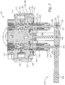
- the manual override device 110 can be assembled to override and control the valves 105 of a hydraulic power system 101 or another system having an electronically controlled valve system. Specifically, the valves 105 are regulated by the independently-controlled movement of spools 112 with respect to first and second ports 116, 117 so as to control flow and pressure provided to or from outputs 118 of the electronically controlled valve system.
- the power system 101 can be a 4-landed, 3-port valve hydraulic power control system, for use, for example, in construction equipment and the first and second ports 116, 117 can be, for example, ports of a closed loop electro-hydraulic control valve which controls flow and pressure to and from a tank or can be service ports.
- the manual override device 110 is assembled to the body 132 of the power system 101 at mounts 134 disposed beneath spools 112 as will be described in further detail below with respect to FIGS. 6-15 .
- the spools 112 control the flow and pressure through ports 116, 117 by moving in a longitudinal direction extending along a central axis CA transverse to the ports 116, 117.
- the mounts 134 are provided below the spools 112 in the longitudinal direction and are preferably concentric to the central axis CA.
- a housing 130 including a plug end 146 of the manual override device 110 is disposed within each mount 134.
- a rod 120 extends centrally through the housing 130 and out of the plug end 146 which includes a sealing ring 147.
- At a first end 121 of the rod 120 is an enlarged diameter section 124 and an extension 150 and at a second end 122 of the rod 120 is a reduced diameter section 123 and a ball end 125.
- a lever 114 for activating the manual override device is attached at the second ends 122 of the rods 120 by slots 115.
- the lever 114 is rotationally attached at a fulcrum 165 via a bracket 160 extending from and connected to the body 132.
- a spring 129 which is preferably a cylindrical spring, is disposed within the housing 130 between the plug end 146 and a stop collar 152 which in turn abuts against a shoulder 154 of the housing 130.
- the stop collar 152 is disposed below the enlarged diameter section 124 of the rod 120.
- each of the rod 120, spring 129, housing 130, plug end 146 and stop collar 152 are disposed concentrically about the central axis CA of the spools 112.
- an attachment 138 which in the embodiment shown is a cutaway receptacle 140, that is attached within a channel 113 extending concentrically along the central axis CA of each spool 112.
- the cutaway receptacle 140 can be configured as a cup having a section cutaway so as to form a semi-circular wall section 141 and a semi-circular lip 142 that extends from the wall section 141 toward the central axis CA.
- the lip 142 of the cutaway receptacle 140 does not extend all the way to the enlarged diameter section 124 of the rod 120 and the extension 150 of the rod 120 does not extend all the way to the wall section 141 of the cutaway receptacle 140.
- the attachment 138 can move together without contact, or "float,” with the spool 112 such that if any components of the manual override device are not disposed exactly concentrically with the spool 112, the clearance C allows for the eccentricity without introducing radial or friction forces which impede the free movement of the spool 112.
- the manual override device 110 is safer, easier to operate and has a significantly increased cycle life.
- the "floating" spool 112 and the clearance C between an attachment 138 to the spool 112 and a first end 121 of the rod 120 which engages the attachment 138 to the spool 112 only when the manual override device 110 is activated by the lever 114 can have different configurations.
- the attachment 138 (which in the above-described embodiment is the cutaway receptacle 140) and the first end 121 of the rod 120 can have different shapes so long as the first end 121 of the rod 120 engages the attachment 138 only when the lever 114 is activated from its rest position.
- the cutaway receptacle 140 can be disposed at the first end 121 of the rod 120 and the attachment 138 can include the extension 150 configured to engage the lip 142 of the cutaway receptacle 140.
- each spring 129 has the same spring force and is disposed an equal distance from the fulcrum 165 of the lever 114 such that the equal and opposite torques applied by the springs 129 hold the lever 114 in the rest position, as seen in FIG. 2 , during ordinary operation.
- the other, opposite spring 129 remains static as the rod 120 slides through the respective spring 129 and the stop collar 152 when the rod 120 is pushed in the longitudinal direction upward by the lever 114. Accordingly, additional spring load is applied only to one side of the lever 114 that is pulled downward in the first direction ( FIG. 3 ) or the second direction ( FIG. 4 ).
- first port 116 could be a pressure port and the second port 117 could be a fuel port and movement of the lever 114 in the first direction ( FIG. 3 ) or the second direction ( FIG. 4 ) can operate to interchangeably add or remove pressure and open or close a tank.
- a power system 101 can include a series of twin valve arrangements each having a respective manual override device 110.
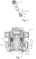
- FIGS. 6-15 an assembly procedure for the manual override device 110 is shown.
- FIGS. 6 and 7 respectively show the spool 112 and the cutaway receptacle 140 in an unassembled state and the cutaway receptacle 140 being connected in the channel 113 of the spool 112 via the shaft 143, which may be, for example, a threaded connection using a dowel diameter which helps facilitate the concentricity of the cutaway receptacle 140 with the spool 112.
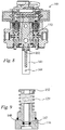
- FIG. 8 illustrates an assembly step of mounting the bracket 160 to the body 132, for example, via screws 161.
- FIG. 9 shows a sectional view of the sub-assembly of the plug end 146, the spring 129 and the stop collar 152.
- FIG. 10 shows an assembly step where the rod 120 is inserted, with the second end 122 first, through the stop collar 152, the spring 129 and the plug end 146 and in which the housing 130 has been connected to the plug end 146, for example by a threaded connection or sealing arrangement.
- FIG. 10 shows an assembly step where the rod 120 is inserted, with the second end 122 first, through the stop collar 152, the spring 129 and the plug end 146 and in which the housing 130 has been connected to the plug end 146, for example by a threaded connection or sealing arrangement.
- FIG. 11 shows an assembly step wherein the extension 150 of the rod 120 is inserted over the lip 142 of the cutaway receptacle 140 so as to be disposed and operable within the clearance C of the cutaway receptacle 140.
- this step includes making the rod 120 concentric with the cutaway receptacle 140 and the spool 112.
- the housing 130 and plug end 146 are pressed upwards and connected, for example by a threaded connection, into the mount 134.
- the assembly is repeated for the other valve 105.
- FIGS. 13 and 14 illustrate an assembly step in which an enlarged section 115A of the slots 115 of the lever 114 are slid through the ball ends 125 of the rods 120 so that the slots 115 line up with the reduced diameter sections 123.
- the lever 114 is moved in a direction D transverse to the longitudinal direction such that the reduced diameter sections 123 of the rods 120 are disposed in the reduced section 115B of the slots 115 and so that the lever mounting hole 162 and the bracket mounting hole 164 align at fulcrum 165 where the lever 114 is rotationally attached to the bracket 160, for example, by a pin connection.
- the slots 115 in the embodiment shown, have a length in the direction D of the lever 114 which allows the rods 120 to slide along the slots 115 in direction D or in the opposite direction in order to maintain the orientation of the rods 120 in the longitudinal direction concentric with the central axis CA when the lever is moved in the first direction ( FIG. 3 ) or the second direction ( FIG. 4 ).
- the assembly steps shown in FIGS. 6-15 can be performed in different orders and in any number of sub-steps. While the invention has been particularly shown and described with reference to preferred embodiments thereof, it will be understood by those skilled in the art that various changes in form and details may be made therein without departing from the scope of the invention. Further, the present invention is not limited to the embodiments described herein; reference should be had to the appended claims.
Landscapes
- Engineering & Computer Science (AREA)
- General Engineering & Computer Science (AREA)
- Mechanical Engineering (AREA)
- Mechanically-Actuated Valves (AREA)
- Preventing Unauthorised Actuation Of Valves (AREA)
- Multiple-Way Valves (AREA)
Claims (12)
- Dispositif de surpassement manuel (110) pour commander au moins un robinet (105) dans un système d'alimentation (101), comprenant :une tige (120) présentant une première extrémité (121) et une seconde extrémité (122) ;un élément de fixation (138) pouvant être fixé à un tiroir (112) de l'au moins un robinet (105), l'élément de fixation (138) incluant un débattement par rapport à la première extrémité (121) de la tige (120) de façon à permettre à l'élément de fixation (138) de se déplacer avec le tiroir (112), pendant un fonctionnement ordinaire du système d'alimentation (101), sans venir en contact avec la tige (120) ;un levier (114) raccordé à la seconde extrémité de la tige (120) et configuré pour activer le dispositif de surpassement manuel (110) en déplaçant la tige (120) dans une direction longitudinale de sorte que la première extrémité (121) de la tige (120) établisse un contact avec l'élément de fixation (138) pour déplacer le tiroir (112), dans lequel l'élément de fixation (138) inclut un réceptacle découpé (140) présentant une lèvre (142) et une paroi latérale et la première extrémité (121) de la tige (120) inclut une extension (150) ;un boîtier (130) pouvant être fixé à un support du système d'alimentation (101) dans la direction longitudinale sous le tiroir (112), le boîtier incluant une extrémité de fiche (146) ; et caractérisé en ce que le boîtier (130) inclut en outreun ressort (129) disposé sur l'extrémité de fiche (146) au sein du boîtier (130) et un collet de butée (152) disposé sur le ressort (129), dans lequel la tige (120) s'étend à travers le boîtier (130), le collet de butée (152), le ressort (129) et l'extrémité de fiche (146).
- Dispositif de surpassement manuel (110) selon la revendication 1, dans lequel l'extension (150) est disposée le long de la paroi latérale entre la paroi latérale et le tiroir (112) de sorte que le débattement inclue une longueur de la paroi latérale.
- Dispositif de surpassement manuel (110) selon la revendication 1, dans lequel la tige (120) inclut une section de diamètre agrandi au niveau de la première extrémité (121) qui est en appui contre le collet de butée (152) pendant le fonctionnement ordinaire du système d'alimentation (101).
- Dispositif de surpassement manuel (110) selon la revendication 1, dans lequel une force de ressort du ressort (129) est supérieure à une pression du système d'alimentation (101) utilisée pour déplacer le tiroir (112) pendant le fonctionnement ordinaire du système d'alimentation (101).
- Système de commande de robinet pour un système d'alimentation (101) comprenant :un tiroir (112) configuré pour se déplacer dans une direction longitudinale de façon à réguler au moins l'un d'un écoulement et d'une pression à travers un orifice ;un élément de fixation (138) fixé de façon concentrique au tiroir (112) ;une tige (120) présentant une première extrémité (121) et une seconde extrémité (122), la première extrémité (121) étant disposée au sein d'un débattement de l'élément de fixation (138) de façon à permettre à l'élément de fixation (138) de se déplacer avec le tiroir (112), pendant un fonctionnement ordinaire du système d'alimentation (101), sans venir en contact avec la tige (120) ;un levier (114) raccordé à la seconde extrémité (122) de la tige (120) et configuré pour activer un surpassement manuel d'une position du tiroir (112) en déplaçant la tige (120) dans une direction longitudinale de sorte que la première extrémité (121) de la tige (120) établisse un contact avec l'élément de fixation (138) pour déplacer le tiroir (112), dans lequel l'élément de fixation (138) inclut un réceptacle découpé (140) présentant une lèvre (142) et une paroi latérale et la première extrémité (121) de la tige (120) inclut une extension (150) ;un boîtier (130) pouvant être fixé à un support du système d'alimentation (101) dans la direction longitudinale sous le tiroir (112), le boîtier (130) incluant une extrémité de fiche (146) ; et caractérisé en ce que le boîtier (130) inclut en outreun ressort (129) disposé sur l'extrémité de fiche au sein du boîtier (130) et un collet de butée (152) disposé sur le ressort (129), dans lequel la tige (120) s'étend à travers le boîtier (130), le collet de butée (152), le ressort (129) et l'extrémité de fiche (146).
- Système de commande de robinet selon la revendication 5, dans lequel l'extension (150) est disposée le long de la paroi latérale entre la paroi latérale et le tiroir (112) de sorte que le débattement inclue une longueur de la paroi latérale.
- Système de commande de robinet selon la revendication 5, dans lequel la tige (120) inclut une section de diamètre agrandi au niveau de la première extrémité (121) qui est en appui contre le collet de butée (152) pendant le fonctionnement ordinaire du système d'alimentation (101).
- Système de commande de robinet selon la revendication 5, dans lequel une force de ressort du ressort (129) est supérieure à une pression du système d'alimentation (101) utilisée pour déplacer le tiroir (112) pendant le fonctionnement ordinaire du système d'alimentation (101).
- Système de commande de robinet selon la revendication 5, dans lequel le système de commande de robinet inclut un agencement à double robinet présentant deux tiroirs (112), présentant chacun l'élément de fixation et régulant des orifices séparés, et deux tiges (120) qui se fixent au levier sur des côtés opposés d'un pivot.
- Système de commande de robinet selon la revendication 5, dans lequel le système d'alimentation (101) est un système d'alimentation hydraulique et l'orifice est au moins l'un d'un orifice de refoulement, d'un orifice de carburant et d'un orifice de maintenance.
- Procédé d'assemblage d'un dispositif de surpassement manuel (110) à un corps d'un système d'alimentation (101), comprenant :le raccordement d'un élément de fixation (138) à un tiroir (112) qui se déplace dans une direction longitudinale pendant un fonctionnement ordinaire du système d'alimentation (101) de façon à réguler au moins l'un d'un écoulement et d'une pression à travers un orifice ;l'insertion d'une première extrémité (121) d'une tige (120) dans un débattement de l'élément de fixation (138) de façon à ce qu'elle soit sensiblement concentrique avec celui-ci et de sorte que le débattement de l'élément de fixation (138) permette à l'élément de fixation (138) de se déplacer avec le tiroir (112), pendant le fonctionnement ordinaire du système d'alimentation (101), sans venir en contact avec la tige (120) ;le raccordement d'un boîtier (130) incluant une extrémité de fiche (146), un ressort (129) disposé sur l'extrémité de fiche et un collet de butée (152) disposé sur le ressort (129) à un support du système d'alimentation (101) de sorte qu'une section de diamètre agrandi de la tige (120) au niveau de la première extrémité (121) soit en appui contre le collet de butée (152) ; etle raccordement d'un levier à une seconde extrémité (122) de la tige (120) de sorte que la tige (120) soit mobile dans la direction longitudinale lorsque le levier est déplacé dans une première direction ou une seconde direction opposée à la première direction de façon à activer un surpassement manuel d'une position du tiroir (112) en déplaçant la tige (120) dans une direction longitudinale de sorte que la première extrémité (121) de la tige (120) établisse un contact avec l'élément de fixation pour déplacer le tiroir (112), dans lequel l'élément de fixation inclut un réceptacle découpé présentant une lèvre et une paroi latérale et la première extrémité (121) de la tige (120) inclut une extension (150) et dans lequel la tige (120) s'étend à travers le boîtier (130), le collet de butée (152), le ressort (129) et l'extrémité de fiche (146).
- Procédé selon la revendication 11, dans lequel la tige (120) est insérée dans le débattement en insérant l'extension (150) le long de la paroi latérale entre la paroi latérale et le tiroir (112).
Applications Claiming Priority (2)
| Application Number | Priority Date | Filing Date | Title |
|---|---|---|---|
| US13/214,304 US8905072B2 (en) | 2011-08-22 | 2011-08-22 | Manual override device for a twin spool valve |
| PCT/EP2012/065986 WO2013026760A1 (fr) | 2011-08-22 | 2012-08-16 | Dispositif de surpassement manuel pour distributeur à tiroir à double corps |
Publications (2)
| Publication Number | Publication Date |
|---|---|
| EP2748468A1 EP2748468A1 (fr) | 2014-07-02 |
| EP2748468B1 true EP2748468B1 (fr) | 2020-04-15 |
Family
ID=46682842
Family Applications (1)
| Application Number | Title | Priority Date | Filing Date |
|---|---|---|---|
| EP12748032.5A Active EP2748468B1 (fr) | 2011-08-22 | 2012-08-16 | Dispositif de surpassement manuel pour distributeur à tiroir à double corps |
Country Status (4)
| Country | Link |
|---|---|
| US (1) | US8905072B2 (fr) |
| EP (1) | EP2748468B1 (fr) |
| CN (1) | CN103827510B (fr) |
| WO (1) | WO2013026760A1 (fr) |
Families Citing this family (3)
| Publication number | Priority date | Publication date | Assignee | Title |
|---|---|---|---|---|
| CN103775725B (zh) * | 2014-02-20 | 2017-02-22 | 特福隆(上海)科技有限公司 | 气动控制操作模块 |
| DK3587830T3 (da) * | 2014-05-01 | 2022-06-13 | Danfoss Power Solutions Ii Technology As | Skydeventilforbindelsesanordning til manuel forbikoblings-indretning |
| CN112728166A (zh) * | 2021-01-04 | 2021-04-30 | 江苏恒立液压科技有限公司 | 油口单独控制的液压多路阀及其控制方法 |
Citations (1)
| Publication number | Priority date | Publication date | Assignee | Title |
|---|---|---|---|---|
| US670250A (en) * | 1900-06-28 | 1901-03-19 | Raphael Ryan | Cut-off. |
Family Cites Families (13)
| Publication number | Priority date | Publication date | Assignee | Title |
|---|---|---|---|---|
| US80461A (en) * | 1868-07-28 | Lithographer | ||
| US3646959A (en) * | 1970-10-12 | 1972-03-07 | Sperry Rand Corp | Power transmission |
| US4017053A (en) * | 1974-02-06 | 1977-04-12 | Willis Oil Tool Co. | Fluid pressure monitoring safety system |
| US4011891A (en) * | 1975-08-06 | 1977-03-15 | Applied Power Inc. | Proportional flow control valve |
| US4071046A (en) * | 1976-10-07 | 1978-01-31 | Cates H Alton | Directional control poppet valve |
| US4360239A (en) * | 1980-01-21 | 1982-11-23 | Mcdonnell Douglas Corporation | Manual/auto brake valve |
| US4627468A (en) * | 1985-08-30 | 1986-12-09 | Husco International, Inc. | Hydraulic control valve with manual override |
| CN85205289U (zh) * | 1985-12-07 | 1987-08-12 | 煤炭科学研究院太原分院 | 具有初始承载力自保作用的抗污染操纵阀 |
| JPH0332869Y2 (fr) * | 1986-12-22 | 1991-07-11 | ||
| DE3810273C2 (de) * | 1988-03-25 | 1994-09-29 | Rexroth Mannesmann Gmbh | Ansteuervorrichtung für ein Wegeventil |
| JP2551538Y2 (ja) * | 1990-02-27 | 1997-10-22 | 株式会社小松製作所 | パイロット弁 |
| FR2687205A1 (fr) * | 1992-02-10 | 1993-08-13 | Rexroth Sigma | Dispositif distributeur de fluide hydraulique pour telecommande hydraulique. |
| CN102032229B (zh) * | 2010-11-12 | 2013-03-27 | 宁波华液机器制造有限公司 | 用于气动阀岛的双阀芯阀 |
-
2011
- 2011-08-22 US US13/214,304 patent/US8905072B2/en active Active
-
2012
- 2012-08-16 WO PCT/EP2012/065986 patent/WO2013026760A1/fr not_active Ceased
- 2012-08-16 CN CN201280040876.8A patent/CN103827510B/zh not_active Expired - Fee Related
- 2012-08-16 EP EP12748032.5A patent/EP2748468B1/fr active Active
Patent Citations (1)
| Publication number | Priority date | Publication date | Assignee | Title |
|---|---|---|---|---|
| US670250A (en) * | 1900-06-28 | 1901-03-19 | Raphael Ryan | Cut-off. |
Also Published As
| Publication number | Publication date |
|---|---|
| US20130048893A1 (en) | 2013-02-28 |
| CN103827510A (zh) | 2014-05-28 |
| WO2013026760A1 (fr) | 2013-02-28 |
| EP2748468A1 (fr) | 2014-07-02 |
| CN103827510B (zh) | 2016-04-20 |
| US8905072B2 (en) | 2014-12-09 |
Similar Documents
| Publication | Publication Date | Title |
|---|---|---|
| EP2872958B1 (fr) | Actionneur solénoïde à action directe | |
| KR101934686B1 (ko) | 개선된 댐핑 거동을 갖는 게이트형 압력 조절 밸브 | |
| TWI705211B (zh) | 適於致動時以洩壓模式操作之電動液壓常開可通氣閥 | |
| EP2505888B1 (fr) | Électrovanne | |
| EP3273186B1 (fr) | Vanne motorisée | |
| EP3129660B1 (fr) | Servovalve | |
| EP2902682B1 (fr) | Soupape pilotée à piston flottant | |
| US20190331249A1 (en) | Proportional Normally-Open Valve with a Biasing Spring | |
| US20160195879A1 (en) | Valve device | |
| KR102186670B1 (ko) | 보상 챔버를 포함한 압력 조절 밸브 | |
| EP2748468B1 (fr) | Dispositif de surpassement manuel pour distributeur à tiroir à double corps | |
| CN103122995B (zh) | 用于操纵变速器的至少一个换挡元件的液压系统的阀装置 | |
| US9841119B2 (en) | Pilot valve arrangement | |
| EP1592906B1 (fr) | Soupape de commande guidee par une tige et sans douille | |
| US10082221B2 (en) | Pilot valve | |
| EP3137775B1 (fr) | Ensemble de prise de priorité manuelle | |
| CN108591151B (zh) | 液压轴向柱塞泵功率控制及正流量控制机构 | |
| JP2014518359A (ja) | 弁、特に圧力調整弁又は圧力制限弁 | |
| US10487960B2 (en) | Hydraulic valve | |
| EP1239356A1 (fr) | Valve de commande à solénoid et amortisseur hydraulic | |
| US10865891B2 (en) | Device for flow force compensation | |
| EP4244511B1 (fr) | Système de soupape | |
| JP2015068481A (ja) | リニアソレノイドバルブ |
Legal Events
| Date | Code | Title | Description |
|---|---|---|---|
| PUAI | Public reference made under article 153(3) epc to a published international application that has entered the european phase |
Free format text: ORIGINAL CODE: 0009012 |
|
| 17P | Request for examination filed |
Effective date: 20140224 |
|
| AK | Designated contracting states |
Kind code of ref document: A1 Designated state(s): AL AT BE BG CH CY CZ DE DK EE ES FI FR GB GR HR HU IE IS IT LI LT LU LV MC MK MT NL NO PL PT RO RS SE SI SK SM TR |
|
| RIN1 | Information on inventor provided before grant (corrected) |
Inventor name: BARNES, MICHAEL, STANLEY Inventor name: HONKALSE, NACHIKET, PANDURANG Inventor name: ARTIS, EVAN, KYLE |
|
| DAX | Request for extension of the european patent (deleted) | ||
| RAP1 | Party data changed (applicant data changed or rights of an application transferred) |
Owner name: EATON INTELLIGENT POWER LIMITED |
|
| STAA | Information on the status of an ep patent application or granted ep patent |
Free format text: STATUS: EXAMINATION IS IN PROGRESS |
|
| 17Q | First examination report despatched |
Effective date: 20190227 |
|
| REG | Reference to a national code |
Ref country code: DE Ref legal event code: R079 Ref document number: 602012069302 Country of ref document: DE Free format text: PREVIOUS MAIN CLASS: F15B0013042000 Ipc: F16K0031600000 |
|
| RIC1 | Information provided on ipc code assigned before grant |
Ipc: F16K 31/14 20060101ALI20190927BHEP Ipc: F16K 31/60 20060101AFI20190927BHEP Ipc: F15B 13/04 20060101ALI20190927BHEP Ipc: F16K 27/00 20060101ALI20190927BHEP |
|
| GRAP | Despatch of communication of intention to grant a patent |
Free format text: ORIGINAL CODE: EPIDOSNIGR1 |
|
| STAA | Information on the status of an ep patent application or granted ep patent |
Free format text: STATUS: GRANT OF PATENT IS INTENDED |
|
| RIN1 | Information on inventor provided before grant (corrected) |
Inventor name: HONKALSE, NACHIKET PANDURANG Inventor name: ARTIS, EVAN KYLE Inventor name: BARNES, MICHAEL STANLEY |
|
| INTG | Intention to grant announced |
Effective date: 20191113 |
|
| GRAS | Grant fee paid |
Free format text: ORIGINAL CODE: EPIDOSNIGR3 |
|
| GRAA | (expected) grant |
Free format text: ORIGINAL CODE: 0009210 |
|
| STAA | Information on the status of an ep patent application or granted ep patent |
Free format text: STATUS: THE PATENT HAS BEEN GRANTED |
|
| AK | Designated contracting states |
Kind code of ref document: B1 Designated state(s): AL AT BE BG CH CY CZ DE DK EE ES FI FR GB GR HR HU IE IS IT LI LT LU LV MC MK MT NL NO PL PT RO RS SE SI SK SM TR |
|
| REG | Reference to a national code |
Ref country code: CH Ref legal event code: EP Ref country code: GB Ref legal event code: FG4D |
|
| REG | Reference to a national code |
Ref country code: DE Ref legal event code: R096 Ref document number: 602012069302 Country of ref document: DE |
|
| REG | Reference to a national code |
Ref country code: IE Ref legal event code: FG4D |
|
| REG | Reference to a national code |
Ref country code: AT Ref legal event code: REF Ref document number: 1257710 Country of ref document: AT Kind code of ref document: T Effective date: 20200515 |
|
| REG | Reference to a national code |
Ref country code: NL Ref legal event code: MP Effective date: 20200415 |
|
| REG | Reference to a national code |
Ref country code: LT Ref legal event code: MG4D |
|
| PG25 | Lapsed in a contracting state [announced via postgrant information from national office to epo] |
Ref country code: LT Free format text: LAPSE BECAUSE OF FAILURE TO SUBMIT A TRANSLATION OF THE DESCRIPTION OR TO PAY THE FEE WITHIN THE PRESCRIBED TIME-LIMIT Effective date: 20200415 Ref country code: NL Free format text: LAPSE BECAUSE OF FAILURE TO SUBMIT A TRANSLATION OF THE DESCRIPTION OR TO PAY THE FEE WITHIN THE PRESCRIBED TIME-LIMIT Effective date: 20200415 Ref country code: PT Free format text: LAPSE BECAUSE OF FAILURE TO SUBMIT A TRANSLATION OF THE DESCRIPTION OR TO PAY THE FEE WITHIN THE PRESCRIBED TIME-LIMIT Effective date: 20200817 Ref country code: GR Free format text: LAPSE BECAUSE OF FAILURE TO SUBMIT A TRANSLATION OF THE DESCRIPTION OR TO PAY THE FEE WITHIN THE PRESCRIBED TIME-LIMIT Effective date: 20200716 Ref country code: FI Free format text: LAPSE BECAUSE OF FAILURE TO SUBMIT A TRANSLATION OF THE DESCRIPTION OR TO PAY THE FEE WITHIN THE PRESCRIBED TIME-LIMIT Effective date: 20200415 Ref country code: NO Free format text: LAPSE BECAUSE OF FAILURE TO SUBMIT A TRANSLATION OF THE DESCRIPTION OR TO PAY THE FEE WITHIN THE PRESCRIBED TIME-LIMIT Effective date: 20200715 Ref country code: IS Free format text: LAPSE BECAUSE OF FAILURE TO SUBMIT A TRANSLATION OF THE DESCRIPTION OR TO PAY THE FEE WITHIN THE PRESCRIBED TIME-LIMIT Effective date: 20200815 Ref country code: SE Free format text: LAPSE BECAUSE OF FAILURE TO SUBMIT A TRANSLATION OF THE DESCRIPTION OR TO PAY THE FEE WITHIN THE PRESCRIBED TIME-LIMIT Effective date: 20200415 |
|
| REG | Reference to a national code |
Ref country code: AT Ref legal event code: MK05 Ref document number: 1257710 Country of ref document: AT Kind code of ref document: T Effective date: 20200415 |
|
| PG25 | Lapsed in a contracting state [announced via postgrant information from national office to epo] |
Ref country code: BG Free format text: LAPSE BECAUSE OF FAILURE TO SUBMIT A TRANSLATION OF THE DESCRIPTION OR TO PAY THE FEE WITHIN THE PRESCRIBED TIME-LIMIT Effective date: 20200715 Ref country code: RS Free format text: LAPSE BECAUSE OF FAILURE TO SUBMIT A TRANSLATION OF THE DESCRIPTION OR TO PAY THE FEE WITHIN THE PRESCRIBED TIME-LIMIT Effective date: 20200415 Ref country code: HR Free format text: LAPSE BECAUSE OF FAILURE TO SUBMIT A TRANSLATION OF THE DESCRIPTION OR TO PAY THE FEE WITHIN THE PRESCRIBED TIME-LIMIT Effective date: 20200415 Ref country code: LV Free format text: LAPSE BECAUSE OF FAILURE TO SUBMIT A TRANSLATION OF THE DESCRIPTION OR TO PAY THE FEE WITHIN THE PRESCRIBED TIME-LIMIT Effective date: 20200415 |
|
| PG25 | Lapsed in a contracting state [announced via postgrant information from national office to epo] |
Ref country code: AL Free format text: LAPSE BECAUSE OF FAILURE TO SUBMIT A TRANSLATION OF THE DESCRIPTION OR TO PAY THE FEE WITHIN THE PRESCRIBED TIME-LIMIT Effective date: 20200415 |
|
| REG | Reference to a national code |
Ref country code: DE Ref legal event code: R097 Ref document number: 602012069302 Country of ref document: DE |
|
| PG25 | Lapsed in a contracting state [announced via postgrant information from national office to epo] |
Ref country code: EE Free format text: LAPSE BECAUSE OF FAILURE TO SUBMIT A TRANSLATION OF THE DESCRIPTION OR TO PAY THE FEE WITHIN THE PRESCRIBED TIME-LIMIT Effective date: 20200415 Ref country code: SM Free format text: LAPSE BECAUSE OF FAILURE TO SUBMIT A TRANSLATION OF THE DESCRIPTION OR TO PAY THE FEE WITHIN THE PRESCRIBED TIME-LIMIT Effective date: 20200415 Ref country code: RO Free format text: LAPSE BECAUSE OF FAILURE TO SUBMIT A TRANSLATION OF THE DESCRIPTION OR TO PAY THE FEE WITHIN THE PRESCRIBED TIME-LIMIT Effective date: 20200415 Ref country code: CZ Free format text: LAPSE BECAUSE OF FAILURE TO SUBMIT A TRANSLATION OF THE DESCRIPTION OR TO PAY THE FEE WITHIN THE PRESCRIBED TIME-LIMIT Effective date: 20200415 Ref country code: ES Free format text: LAPSE BECAUSE OF FAILURE TO SUBMIT A TRANSLATION OF THE DESCRIPTION OR TO PAY THE FEE WITHIN THE PRESCRIBED TIME-LIMIT Effective date: 20200415 Ref country code: AT Free format text: LAPSE BECAUSE OF FAILURE TO SUBMIT A TRANSLATION OF THE DESCRIPTION OR TO PAY THE FEE WITHIN THE PRESCRIBED TIME-LIMIT Effective date: 20200415 Ref country code: DK Free format text: LAPSE BECAUSE OF FAILURE TO SUBMIT A TRANSLATION OF THE DESCRIPTION OR TO PAY THE FEE WITHIN THE PRESCRIBED TIME-LIMIT Effective date: 20200415 |
|
| PLBE | No opposition filed within time limit |
Free format text: ORIGINAL CODE: 0009261 |
|
| STAA | Information on the status of an ep patent application or granted ep patent |
Free format text: STATUS: NO OPPOSITION FILED WITHIN TIME LIMIT |
|
| PG25 | Lapsed in a contracting state [announced via postgrant information from national office to epo] |
Ref country code: SK Free format text: LAPSE BECAUSE OF FAILURE TO SUBMIT A TRANSLATION OF THE DESCRIPTION OR TO PAY THE FEE WITHIN THE PRESCRIBED TIME-LIMIT Effective date: 20200415 Ref country code: PL Free format text: LAPSE BECAUSE OF FAILURE TO SUBMIT A TRANSLATION OF THE DESCRIPTION OR TO PAY THE FEE WITHIN THE PRESCRIBED TIME-LIMIT Effective date: 20200415 |
|
| 26N | No opposition filed |
Effective date: 20210118 |
|
| PG25 | Lapsed in a contracting state [announced via postgrant information from national office to epo] |
Ref country code: MC Free format text: LAPSE BECAUSE OF FAILURE TO SUBMIT A TRANSLATION OF THE DESCRIPTION OR TO PAY THE FEE WITHIN THE PRESCRIBED TIME-LIMIT Effective date: 20200415 |
|
| REG | Reference to a national code |
Ref country code: CH Ref legal event code: PL |
|
| PG25 | Lapsed in a contracting state [announced via postgrant information from national office to epo] |
Ref country code: CH Free format text: LAPSE BECAUSE OF NON-PAYMENT OF DUE FEES Effective date: 20200831 Ref country code: LI Free format text: LAPSE BECAUSE OF NON-PAYMENT OF DUE FEES Effective date: 20200831 Ref country code: LU Free format text: LAPSE BECAUSE OF NON-PAYMENT OF DUE FEES Effective date: 20200816 |
|
| REG | Reference to a national code |
Ref country code: BE Ref legal event code: MM Effective date: 20200831 |
|
| PG25 | Lapsed in a contracting state [announced via postgrant information from national office to epo] |
Ref country code: SI Free format text: LAPSE BECAUSE OF FAILURE TO SUBMIT A TRANSLATION OF THE DESCRIPTION OR TO PAY THE FEE WITHIN THE PRESCRIBED TIME-LIMIT Effective date: 20200415 |
|
| PG25 | Lapsed in a contracting state [announced via postgrant information from national office to epo] |
Ref country code: BE Free format text: LAPSE BECAUSE OF NON-PAYMENT OF DUE FEES Effective date: 20200831 Ref country code: IE Free format text: LAPSE BECAUSE OF NON-PAYMENT OF DUE FEES Effective date: 20200816 |
|
| REG | Reference to a national code |
Ref country code: GB Ref legal event code: 732E Free format text: REGISTERED BETWEEN 20211210 AND 20211215 |
|
| REG | Reference to a national code |
Ref country code: DE Ref legal event code: R081 Ref document number: 602012069302 Country of ref document: DE Owner name: DANFOSS A/S, DK Free format text: FORMER OWNER: EATON INTELLIGENT POWER LIMITED, DUBLIN, IE Ref country code: DE Ref legal event code: R081 Ref document number: 602012069302 Country of ref document: DE Owner name: DANFOSS POWER SOLUTIONS II TECHNOLOGY A/S, DK Free format text: FORMER OWNER: EATON INTELLIGENT POWER LIMITED, DUBLIN, IE |
|
| PG25 | Lapsed in a contracting state [announced via postgrant information from national office to epo] |
Ref country code: TR Free format text: LAPSE BECAUSE OF FAILURE TO SUBMIT A TRANSLATION OF THE DESCRIPTION OR TO PAY THE FEE WITHIN THE PRESCRIBED TIME-LIMIT Effective date: 20200415 Ref country code: MT Free format text: LAPSE BECAUSE OF FAILURE TO SUBMIT A TRANSLATION OF THE DESCRIPTION OR TO PAY THE FEE WITHIN THE PRESCRIBED TIME-LIMIT Effective date: 20200415 Ref country code: CY Free format text: LAPSE BECAUSE OF FAILURE TO SUBMIT A TRANSLATION OF THE DESCRIPTION OR TO PAY THE FEE WITHIN THE PRESCRIBED TIME-LIMIT Effective date: 20200415 |
|
| PG25 | Lapsed in a contracting state [announced via postgrant information from national office to epo] |
Ref country code: MK Free format text: LAPSE BECAUSE OF FAILURE TO SUBMIT A TRANSLATION OF THE DESCRIPTION OR TO PAY THE FEE WITHIN THE PRESCRIBED TIME-LIMIT Effective date: 20200415 |
|
| REG | Reference to a national code |
Ref country code: DE Ref legal event code: R082 Ref document number: 602012069302 Country of ref document: DE Representative=s name: KEIL & SCHAAFHAUSEN PATENTANWAELTE PARTGMBB, DE |
|
| P01 | Opt-out of the competence of the unified patent court (upc) registered |
Effective date: 20230617 |
|
| PGFP | Annual fee paid to national office [announced via postgrant information from national office to epo] |
Ref country code: IT Payment date: 20230711 Year of fee payment: 12 Ref country code: GB Payment date: 20230706 Year of fee payment: 12 |
|
| PGFP | Annual fee paid to national office [announced via postgrant information from national office to epo] |
Ref country code: FR Payment date: 20230721 Year of fee payment: 12 Ref country code: DE Payment date: 20230705 Year of fee payment: 12 |
|
| REG | Reference to a national code |
Ref country code: DE Ref legal event code: R119 Ref document number: 602012069302 Country of ref document: DE |
|
| REG | Reference to a national code |
Ref country code: DE Ref legal event code: R081 Ref document number: 602012069302 Country of ref document: DE Owner name: DANFOSS A/S, DK Free format text: FORMER OWNER: DANFOSS POWER SOLUTIONS II TECHNOLOGY A/S, NORDBORG, DK |
|
| GBPC | Gb: european patent ceased through non-payment of renewal fee |
Effective date: 20240816 |
|
| PG25 | Lapsed in a contracting state [announced via postgrant information from national office to epo] |
Ref country code: DE Free format text: LAPSE BECAUSE OF NON-PAYMENT OF DUE FEES Effective date: 20250301 |
|
| PG25 | Lapsed in a contracting state [announced via postgrant information from national office to epo] |
Ref country code: GB Free format text: LAPSE BECAUSE OF NON-PAYMENT OF DUE FEES Effective date: 20240816 |
|
| PG25 | Lapsed in a contracting state [announced via postgrant information from national office to epo] |
Ref country code: IT Free format text: LAPSE BECAUSE OF NON-PAYMENT OF DUE FEES Effective date: 20240816 |
|
| PG25 | Lapsed in a contracting state [announced via postgrant information from national office to epo] |
Ref country code: FR Free format text: LAPSE BECAUSE OF NON-PAYMENT OF DUE FEES Effective date: 20240831 |