EP2748565B1 - Débitmètre - Google Patents
Débitmètre Download PDFInfo
- Publication number
- EP2748565B1 EP2748565B1 EP12756672.7A EP12756672A EP2748565B1 EP 2748565 B1 EP2748565 B1 EP 2748565B1 EP 12756672 A EP12756672 A EP 12756672A EP 2748565 B1 EP2748565 B1 EP 2748565B1
- Authority
- EP
- European Patent Office
- Prior art keywords
- flow
- flow sensor
- measuring
- pressure
- determined
- Prior art date
- Legal status (The legal status is an assumption and is not a legal conclusion. Google has not performed a legal analysis and makes no representation as to the accuracy of the status listed.)
- Active
Links
Images


Classifications
-
- G—PHYSICS
- G01—MEASURING; TESTING
- G01F—MEASURING VOLUME, VOLUME FLOW, MASS FLOW OR LIQUID LEVEL; METERING BY VOLUME
- G01F9/00—Measuring volume flow relative to another variable, e.g. of liquid fuel for an engine
-
- G—PHYSICS
- G01—MEASURING; TESTING
- G01F—MEASURING VOLUME, VOLUME FLOW, MASS FLOW OR LIQUID LEVEL; METERING BY VOLUME
- G01F1/00—Measuring the volume flow or mass flow of fluid or fluent solid material wherein the fluid passes through a meter in a continuous flow
- G01F1/05—Measuring the volume flow or mass flow of fluid or fluent solid material wherein the fluid passes through a meter in a continuous flow by using mechanical effects
- G01F1/34—Measuring the volume flow or mass flow of fluid or fluent solid material wherein the fluid passes through a meter in a continuous flow by using mechanical effects by measuring pressure or differential pressure
- G01F1/36—Measuring the volume flow or mass flow of fluid or fluent solid material wherein the fluid passes through a meter in a continuous flow by using mechanical effects by measuring pressure or differential pressure the pressure or differential pressure being created by the use of flow constriction
- G01F1/40—Details of construction of the flow constriction devices
- G01F1/42—Orifices or nozzles
-
- G—PHYSICS
- G01—MEASURING; TESTING
- G01F—MEASURING VOLUME, VOLUME FLOW, MASS FLOW OR LIQUID LEVEL; METERING BY VOLUME
- G01F1/00—Measuring the volume flow or mass flow of fluid or fluent solid material wherein the fluid passes through a meter in a continuous flow
- G01F1/05—Measuring the volume flow or mass flow of fluid or fluent solid material wherein the fluid passes through a meter in a continuous flow by using mechanical effects
- G01F1/34—Measuring the volume flow or mass flow of fluid or fluent solid material wherein the fluid passes through a meter in a continuous flow by using mechanical effects by measuring pressure or differential pressure
-
- G—PHYSICS
- G01—MEASURING; TESTING
- G01F—MEASURING VOLUME, VOLUME FLOW, MASS FLOW OR LIQUID LEVEL; METERING BY VOLUME
- G01F1/00—Measuring the volume flow or mass flow of fluid or fluent solid material wherein the fluid passes through a meter in a continuous flow
- G01F1/05—Measuring the volume flow or mass flow of fluid or fluent solid material wherein the fluid passes through a meter in a continuous flow by using mechanical effects
- G01F1/34—Measuring the volume flow or mass flow of fluid or fluent solid material wherein the fluid passes through a meter in a continuous flow by using mechanical effects by measuring pressure or differential pressure
- G01F1/36—Measuring the volume flow or mass flow of fluid or fluent solid material wherein the fluid passes through a meter in a continuous flow by using mechanical effects by measuring pressure or differential pressure the pressure or differential pressure being created by the use of flow constriction
- G01F1/363—Measuring the volume flow or mass flow of fluid or fluent solid material wherein the fluid passes through a meter in a continuous flow by using mechanical effects by measuring pressure or differential pressure the pressure or differential pressure being created by the use of flow constriction with electrical or electro-mechanical indication
-
- G—PHYSICS
- G01—MEASURING; TESTING
- G01F—MEASURING VOLUME, VOLUME FLOW, MASS FLOW OR LIQUID LEVEL; METERING BY VOLUME
- G01F1/00—Measuring the volume flow or mass flow of fluid or fluent solid material wherein the fluid passes through a meter in a continuous flow
- G01F1/05—Measuring the volume flow or mass flow of fluid or fluent solid material wherein the fluid passes through a meter in a continuous flow by using mechanical effects
- G01F1/34—Measuring the volume flow or mass flow of fluid or fluent solid material wherein the fluid passes through a meter in a continuous flow by using mechanical effects by measuring pressure or differential pressure
- G01F1/48—Measuring the volume flow or mass flow of fluid or fluent solid material wherein the fluid passes through a meter in a continuous flow by using mechanical effects by measuring pressure or differential pressure the pressure or differential pressure being created by a capillary element
-
- G—PHYSICS
- G01—MEASURING; TESTING
- G01F—MEASURING VOLUME, VOLUME FLOW, MASS FLOW OR LIQUID LEVEL; METERING BY VOLUME
- G01F1/00—Measuring the volume flow or mass flow of fluid or fluent solid material wherein the fluid passes through a meter in a continuous flow
- G01F1/05—Measuring the volume flow or mass flow of fluid or fluent solid material wherein the fluid passes through a meter in a continuous flow by using mechanical effects
- G01F1/34—Measuring the volume flow or mass flow of fluid or fluent solid material wherein the fluid passes through a meter in a continuous flow by using mechanical effects by measuring pressure or differential pressure
- G01F1/50—Correcting or compensating means
-
- G—PHYSICS
- G01—MEASURING; TESTING
- G01F—MEASURING VOLUME, VOLUME FLOW, MASS FLOW OR LIQUID LEVEL; METERING BY VOLUME
- G01F15/00—Details of, or accessories for, apparatus of groups G01F1/00 - G01F13/00 insofar as such details or appliances are not adapted to particular types of such apparatus
- G01F15/001—Means for regulating or setting the meter for a predetermined quantity
- G01F15/003—Means for regulating or setting the meter for a predetermined quantity using electromagnetic, electric or electronic means
-
- G—PHYSICS
- G01—MEASURING; TESTING
- G01F—MEASURING VOLUME, VOLUME FLOW, MASS FLOW OR LIQUID LEVEL; METERING BY VOLUME
- G01F15/00—Details of, or accessories for, apparatus of groups G01F1/00 - G01F13/00 insofar as such details or appliances are not adapted to particular types of such apparatus
- G01F15/005—Valves
-
- G—PHYSICS
- G01—MEASURING; TESTING
- G01N—INVESTIGATING OR ANALYSING MATERIALS BY DETERMINING THEIR CHEMICAL OR PHYSICAL PROPERTIES
- G01N11/00—Investigating flow properties of materials, e.g. viscosity, plasticity; Analysing materials by determining flow properties
- G01N11/02—Investigating flow properties of materials, e.g. viscosity, plasticity; Analysing materials by determining flow properties by measuring flow of the material
-
- G—PHYSICS
- G01—MEASURING; TESTING
- G01N—INVESTIGATING OR ANALYSING MATERIALS BY DETERMINING THEIR CHEMICAL OR PHYSICAL PROPERTIES
- G01N11/00—Investigating flow properties of materials, e.g. viscosity, plasticity; Analysing materials by determining flow properties
- G01N2011/006—Determining flow properties indirectly by measuring other parameters of the system
Definitions
- the invention relates to flow sensors having at least three measurement chambers arranged one behind the other, which are each fluidly connected to each other by a flow resistance, wherein at least two of the flow resistances have a different pressure loss coefficient.
- the invention further relates to metering devices having such flow sensors, and to methods for determining a volume flow and / or a viscosity of a fluid with such flow sensors.
- the dosing device and the dosing rate determination means are arranged separately and not necessarily in a spatially constant position relative to one another, which influences the differential pressure regulation by the resulting undefined hydrostatic pressure differences. In order to ensure exact dosing rates over longer periods of time, these effects must be taken into account if necessary. This leads to a complex regulation.
- a known from the prior art flow sensor for measuring small flow rates in the microliter range for example, the so-called. MEMS flow sensor from. Seyonic, CH-2000 Neucbirtel, Switzerland.
- This flow sensor is used in pipetting systems and includes a measuring channel, a piezoresistive pressure sensor and a temperature sensor.
- the disadvantage of this flow sensor is that the measured flow rates are dependent on the temperature due to dynamic viscosity influences and in addition to the flow, the temperature or the viscosity of the fluid to be measured must be taken into account. It is accordingly necessary to calibrate the flow sensor before the measurement.
- the pressure drop across each membrane is determined by electronically measuring the elongation of the membrane and determining the pressure difference from this strain.
- the influence that the first membrane exerts on the second membrane as it flows through the liquid is not considered.
- the pressure loss coefficients ⁇ 1 and ⁇ 2 for the flow through the membrane openings are equated.
- a straight pipe section is designed so that two capillaries are arranged one behind the other.
- the first capillary serves to form the flow profile, and thus and to reduce the pressure drop due to the throttling when entering the second capillary.
- the second capillary represents a measuring capillary, via which the pressure drop is measured.
- the total pressure drop across the pipe is made up of the largest possible reduction in throttling and the amount of friction.
- This friction pressure is a viscosity-dependent or temperature-dependent variable.
- the proposed in the thesis configuration allows to minimize the pressure component of the throttling of the fluid to be measured, so as to measure substantially only the friction effect. The measured pressure drop is still dependent on the viscosity and the temperature.
- the object of the invention is to provide a flow sensor which can be produced inexpensively, preferably as a disposable product, and with which small quantities of liquid can be precisely measured.
- Another object of the invention is to provide a flow sensor with which a flow rate of a fluid can be measured without knowledge of the exact viscosity and / or temperature of the fluid, or in which no prior calibration is necessary.
- a metering device which can be manufactured as a cost-effective disposable product and with which small quantities of fluid can be precisely metered.
- a metering device according to the invention should allow the volume of a single metered drop to be measured.
- a flow sensor comprises at least three measurement chambers arranged one behind the other, each of which is fluidly connected to one another by a flow resistance. At least two of the flow resistances have a different one Pressure loss coefficient ⁇ open.
- a pressure measuring means is provided, which is adapted to measure the pressure p in the corresponding measuring chamber.
- the flow sensor according to the invention is intended in particular for single use.
- three measuring chambers are arranged serially one behind the other.
- the middle of the three measuring chambers has a smaller volume than the other two measuring chambers.
- the first flow resistance influences the subsequent flow resistance in such a way that the exiting fluid flow does not completely propagate in the second measuring chamber and thus can partially maintain its flow profile. Since the fluid flow is directed to the second frictional channel, as a result, the throttling effect of the inlet opening decreases accordingly, and the pressure loss coefficient is lower.
- the flow resistances are advantageously designed such that they each have a friction channel with a specific length L1, L2 and a specific cross-sectional area A1, A2.
- the lengths L1 and L2 and / or the cross-sectional areas A1 and A2 of the friction channels can be chosen the same or different.
- the cross-sectional areas A1, A2 have a value between 0.03 and 0.3 mm 2 , alternatively or additionally, the length L1, L2 of the friction channels is smaller than 2 mm.
- the flow sensor according to the invention can be injection-molded, preferably in one piece, and thus manufactured as inexpensively as possible.
- the flow sensor is made of plastic.
- the flow sensor has a valve device connected downstream of the last measuring chamber, preferably an electromagnetically operable valve.
- the inventive arrangement of the flow sensor with the valve device succeeds when using a suitable valve device, inter alia, to dose individual drops of the fluid, while measuring the volume of each dosed drop or to check. These values can also be recorded, for example for quality control.
- a flow sensor according to the invention is provided as previously discussed, and for at least two flow resistances of the flow sensor with different pressure loss coefficients ⁇ a characteristic field of a plurality of isobars Characteristics provided, said isobaric characteristic curves represent volume flow viscosity value pairs, which cause a certain differential pressure at the corresponding flow resistance.
- the differential pressures ⁇ p are determined via the corresponding at least two flow resistances by measuring the pressures in the corresponding measuring chambers with the pressure measuring means and calculating the differential pressures therefrom.
- the determined at least two differential pressures are assigned the corresponding isobaric characteristic curve with the same differential pressure in the respective characteristic fields, and the point of intersection of the associated at least two isobaric characteristic curves is determined. From this specific point of intersection, the associated volume flow [V / t] M and / or the associated viscosity ⁇ M are subsequently determined.
- the pressure loss coefficient ⁇ takes into account the flow profile at the inlet into the friction channel.
- ⁇ is the density of the fluid.
- This three-dimensional function may be adjusted so that with ⁇ , ⁇ , I R, r R as fixed parameters the pressure drop Dp as a three-dimensional function of the volume flow [V / t] and the viscosity ⁇ can be represented. From this function, characteristic curves for a specific ⁇ p can be calculated.
- Such a method according to the invention thus makes it possible to determine a flow or volumetric flow without having to know the viscosity. Viscosity even results in flow measurement as an additional measurement.
- the isobaric characteristics of the characteristic curves of the flow resistances are extrapolated from suitable characteristic values, preferably from characteristic values determined by measurements.
- the differential pressures can be determined as a function of time. This allows a precise integration, for example, of individual drop volumes.
- characteristic curves apply only to specific fluid densities ⁇ .
- the density of the fluid must therefore be known. However, the density is usually known, or at least easy to determine.
- four-dimensional functions can also be used, with density as an additional function parameter. From these three-dimensional isobaric characteristics can then be determined.
- three intersecting isobaric characteristics are required, that is also three flow resistances with different pressure loss coefficients.
- the flow sensor 10 according to the invention is used in a dosing system 90, for example for a bioreactor 94.
- the fluid 96 to be metered is transported by a reservoir 93 via a transfer line 95 to a metering device 92, which comprises the flow sensor 10 according to the invention and a valve device 50.
- the fluid to be metered is supplied to the bioreactor 94 in individual drops 97.
- the flow sensor 10 and the metering valve 50 are advantageously formed in one piece, preferably as a disposable unit.
- a flow control device 91 controls the opening time and / or the frequency of the metering valve 50 on the basis of a preset pre-set metering rate by the user and the second actual metering rate measured by the flow meter 10 according to the invention. so that the actual dosing rate corresponds to the desired dosing rate.
- FIG. 2 shows a simplified simplified flow sensor 10 according to the invention with a first measuring chamber 11, a second measuring chamber 15 and a third measuring chamber 19.
- the measuring chambers are connected by a first flow resistance 13 and a second flow resistance 17 with each other.
- the flow resistances 13 and 17 are formed by a first 14 and a second 18 friction channel with a cross-sectional area A1, A2 and a length L1, L2.
- the pressure loss coefficients ⁇ for the flow resistances are designed differently.
- the second measuring chamber 15 is smaller, in particular shorter, designed as, for example, the first measuring chamber 11.
- the measuring chamber 15 is designed so that an outlet opening of the first Reibungskanais 14 is disposed in a suitably small distance from an inlet opening of the second flow channel 18.
- the airfoil has no time to spread evenly in the measuring chamber.
- the fluid flow is directed as it were to the inlet opening.
- the throttling effect of the inlet opening decreases in relation to the theoretically expected value due to the geometry. This results in different pressure loss coefficients for the two flow resistances 13 and 17.
- Optimal geometries for the measuring chambers and friction channels can be determined by mathematical models and / or numerical simulations depending on a preferred range of viscosity, density and volumetric flow. Can be optimized in particular with regard to the accuracy of the determination of the volume flow according to the inventive method.
- Per measuring chamber per a pressure measuring means 12, 16, 20 is provided.
- it is a disposable pressure sensor from the company Freescale Semiconductor, http://www.freescale.com, type MPX2300DT1 and / or type MPX2301DT1.
- the differential pressures ⁇ p1 and ⁇ p2 are determined by determining the difference from the pressure values p1, p2, p3 in the measuring chambers.
- FIG. 3 shows a flow sensor 10 according to the invention as part of a metering device according to the invention, wherein the flow sensor is fluidly connected to a valve device 50.
- this is an electromagnetically actuated valve.
- a magnetic armature 51 is displaced in a valve chamber 55 with a specific clock frequency with a magnetic coil 51, thereby opening an outlet opening 57 of a valve nozzle during a likewise determinable duration and then resealing it.
- the armature 52 of the metering valve 50 is preferably arranged in a capsule that protects it from aggressive media, such as dilute acids.
- the flow sensor 10 and the metering valve 50 are integrally formed.
- a characteristic field is created, which represents the relationship between volume flow, viscosity and pressure drop across the flow resistance.
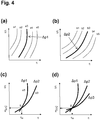
- FIG. 4 (a) is such a characteristic field shown symbolically, with a plurality of characteristics a1 - a5, which represent different pressure differences across the flow resistance.
- FIG. 4 (b) is such a characteristic field shown symbolically, with a plurality of characteristics a1 - a5, which represent different pressure differences across the flow resistance.
- FIG. 4 (b) shows a different pressure loss coefficient
- the characteristics b1 to b5 are tilted in comparison with those of the first flow resistance. If the actual pressure differences .DELTA.p1, .DELTA.p2 are now determined experimentally, they can be assigned the corresponding characteristic curves a3, b3 in the respective characteristic fields.
- FIG. 4 (d) shows a variant in which three differential pressures over three flow resistance with different pressure loss coefficient ⁇ are measured, and cut according to three characteristics. The additional measurement increases the measuring accuracy.
Landscapes
- Physics & Mathematics (AREA)
- General Physics & Mathematics (AREA)
- Fluid Mechanics (AREA)
- Electromagnetism (AREA)
- Chemical & Material Sciences (AREA)
- Life Sciences & Earth Sciences (AREA)
- Health & Medical Sciences (AREA)
- Analytical Chemistry (AREA)
- Biochemistry (AREA)
- General Health & Medical Sciences (AREA)
- Immunology (AREA)
- Pathology (AREA)
- Measuring Volume Flow (AREA)
Claims (12)
- Débitmètre (10), en particulier pour usage unique, comprenant au moins trois chambres de mesure (11, 15, 19) agencés l'une derrière l'autre, qui sont respectivement raccordées l'une à l'autre en mode fluidique par une résistance hydraulique (13, 17), dans lequel il est prévu pour chaque chambre de mesure un moyen de mesure de pression (12, 16, 20), qui convient pour mesurer la pression (p1, p2, p3) dans la chambre de mesure correspondante, caractérisé en ce qu'au moins deux des résistances hydrauliques présentent un facteur de correction de perte de pression différent (ζ1, ζ2).
- Débitmètre selon la revendication 1, caractérisé par trois chambres de mesure (11, 15, 19) agencées en série l'une derrière l'autre.
- Débitmètre selon la revendication 1 ou 2, caractérisé en ce que les résistances hydrauliques (13, 17) présentent respectivement un canal de friction (14, 18) d'une longueur déterminée (L1, L2) et d'une surface en coupe transversale déterminée (A1, A2).
- Débitmètre selon la revendication 3, caractérisé en ce que les surfaces en coupe transversale (A1, A2) des canaux de friction (14, 18) présentent une valeur comprise entre 0,03 et 0,3 mm2.
- Débitmètre selon la revendication 3 ou 4, caractérisé en ce que la longueur (L1, L2) des canaux de friction (14, 18) est inférieure à 2 mm.
- Débitmètre selon l'une quelconque des revendications précédentes, caractérisé en ce que les moyens de mesure de pression (12, 16, 20) sont des capteurs de pression à semi-conducteurs.
- Débitmètre selon l'une quelconque des revendications précédentes, caractérisé en ce que le débitmètre (20) est constitué d'une matière plastique et/ou est moulé par injection.
- Débitmètre selon l'une quelconque des revendications précédentes, caractérisé par un dispositif à soupape (50) monté en aval de la dernière chambre de mesure (19), de préférence une soupape à commande électromagnétique.
- Dispositif de dosage (92) pour doser des fluides, comprenant un canal d'alimentation (21) pour acheminer le fluide à doser ; un débitmètre (10) selon l'une quelconque des revendications 1 à 8 pour déterminer le courant volumique à travers le débitmètre, dans lequel le canal d'alimentation est raccordé en mode fluidique à la première chambre de mesure (11) du débitmètre ; et un dispositif à soupape (50) pour doser le fluide, de préférence une soupape à commande électromagnétique, dans lequel la dernière chambre de mesure (19) est raccordée à l'entrée du dispositif à soupape.
- Procédé de mesure d'un courant volumique ([V/t]M) et/ou d'une viscosité (ηM) d'un fluide, dans lequel :- un débitmètre (10) selon l'une quelconque des revendications 1 à 8 est mis en oeuvre ;- pour au moins deux résistances hydrauliques (13, 17) du débitmètre avec des facteurs de correction de perte de pression différents (ζ1, ζ2), on met en oeuvre un champ de caractéristiques formé d'une pluralité de caractéristiques isobares (a1...a5, b1...b5), dans lequel les caractéristiques isobares mentionnées représentent des paires de valeurs de courant volumique et de viscosité qui provoquent une pression différentielle déterminée dans le cadre de la résistance hydraulique correspondante ;- les pressions différentielles (Δp1, Δp2) sont déterminées via les au moins deux résistances hydrauliques correspondantes en mesurant avec les moyens de mesure de pression (12, 16, 20) les pressions (p1, p2, p3) dans les chambres de mesure correspondantes (11, 15, 19) et en en tirant les pressions différentielles par calcul ;- la caractéristique isobare correspondante (a3, b3) est affectée avec la même pression différentielle aux au moins deux pressions différentielles déterminées dans les champs de caractéristiques respectifs ;- on détermine le point d'intersection (S) des au moins deux caractéristiques isobares affectées ;- on détermine à partir du point d'intersection déterminé le courant volumique connexe ([V/t]M) et/ou la viscosité connexe (ηM).
- Procédé selon la revendication 10, caractérisé en ce que les caractéristiques isobares des champs de caractéristiques des résistances hydrauliques sont extrapolées à partir de valeurs caractéristiques appropriées, de préférence à partir de valeurs caractéristiques déterminées par des mesures.
- Procédé selon la revendication 10 ou 11, caractérisé en ce que les pressions différentielles (Δp1, Δp2) sont déterminées en fonction du temps (t).
Applications Claiming Priority (3)
| Application Number | Priority Date | Filing Date | Title |
|---|---|---|---|
| CH13982011 | 2011-08-26 | ||
| CH01785/11A CH705730A1 (de) | 2011-11-03 | 2011-11-03 | Durchflusssensor. |
| PCT/EP2012/066227 WO2013030034A1 (fr) | 2011-08-26 | 2012-08-21 | Capteur de débit |
Publications (2)
| Publication Number | Publication Date |
|---|---|
| EP2748565A1 EP2748565A1 (fr) | 2014-07-02 |
| EP2748565B1 true EP2748565B1 (fr) | 2017-08-16 |
Family
ID=46829710
Family Applications (1)
| Application Number | Title | Priority Date | Filing Date |
|---|---|---|---|
| EP12756672.7A Active EP2748565B1 (fr) | 2011-08-26 | 2012-08-21 | Débitmètre |
Country Status (4)
| Country | Link |
|---|---|
| US (1) | US9739653B2 (fr) |
| EP (1) | EP2748565B1 (fr) |
| CA (1) | CA2843815A1 (fr) |
| WO (1) | WO2013030034A1 (fr) |
Cited By (1)
| Publication number | Priority date | Publication date | Assignee | Title |
|---|---|---|---|---|
| DE102018200314A1 (de) | 2018-01-11 | 2019-07-11 | Robert Bosch Gmbh | Dosierventil und Strahlpumpeneinheit zum Steuern eines gasförmigen Mediums |
Families Citing this family (6)
| Publication number | Priority date | Publication date | Assignee | Title |
|---|---|---|---|---|
| FR3047067B1 (fr) * | 2016-01-22 | 2019-07-05 | Elvesys | Systeme de mesure de debit d'un liquide et son utilisation |
| WO2018075723A1 (fr) * | 2016-10-19 | 2018-04-26 | Medtec Medical, Inc. | Débitmètre électronique comprenant un régulateur |
| JP7193088B2 (ja) * | 2019-03-26 | 2022-12-20 | 国立研究開発法人産業技術総合研究所 | 差圧式流量計 |
| CN110539470B (zh) * | 2019-09-06 | 2021-05-07 | 青岛科技大学 | 一种在线测量橡胶挤出机计量段中橡胶粘度的装置和方法 |
| DE102019134804A1 (de) * | 2019-12-17 | 2021-06-17 | Reseatech Gmbh | Messanordnung mit einem mikromechanischen Sensor zum Erfassen von Eigenschaften eines strömenden Fluids |
| FR3126773B1 (fr) | 2021-09-08 | 2023-09-01 | Elvesys | Systeme de mesure de debit de liquide dans une canalisation micro-fluidique |
Family Cites Families (8)
| Publication number | Priority date | Publication date | Assignee | Title |
|---|---|---|---|---|
| US3924467A (en) * | 1973-07-01 | 1975-12-09 | Ono Sokki Seiksakusho Kk | Flowmeter |
| CA1224945A (fr) * | 1984-06-25 | 1987-08-04 | Victor Equipment Company | Debitmetre a deux orifices |
| DE8804698U1 (de) * | 1988-04-09 | 1988-06-01 | Labionics Ag, Niederurnen | Durchflußmeßvorrichtung für Fluide |
| DE19650115C1 (de) * | 1996-12-03 | 1998-07-02 | Fraunhofer Ges Forschung | Medikamenten-Dosiervorrichtung |
| TW421710B (en) * | 1999-04-13 | 2001-02-11 | Inst Of Nuclear Energy Res Roc | Method and device for bi-directional low-velocity flow measurement |
| WO2008025935A1 (fr) * | 2006-08-29 | 2008-03-06 | Richard Steven | Améliorations relatives à la mesure d'un débit |
| JP5703032B2 (ja) * | 2011-01-06 | 2015-04-15 | 株式会社フジキン | ガス供給装置用流量制御器の流量測定方法 |
| WO2013002656A1 (fr) * | 2011-06-30 | 2013-01-03 | Lee Pedro Jose | Procédé de détermination de débit et appareil associé |
-
2012
- 2012-08-21 WO PCT/EP2012/066227 patent/WO2013030034A1/fr not_active Ceased
- 2012-08-21 EP EP12756672.7A patent/EP2748565B1/fr active Active
- 2012-08-21 CA CA2843815A patent/CA2843815A1/fr not_active Abandoned
- 2012-08-21 US US14/239,906 patent/US9739653B2/en not_active Expired - Fee Related
Non-Patent Citations (1)
| Title |
|---|
| None * |
Cited By (1)
| Publication number | Priority date | Publication date | Assignee | Title |
|---|---|---|---|---|
| DE102018200314A1 (de) | 2018-01-11 | 2019-07-11 | Robert Bosch Gmbh | Dosierventil und Strahlpumpeneinheit zum Steuern eines gasförmigen Mediums |
Also Published As
| Publication number | Publication date |
|---|---|
| CA2843815A1 (fr) | 2013-03-07 |
| US20140208833A1 (en) | 2014-07-31 |
| US9739653B2 (en) | 2017-08-22 |
| WO2013030034A1 (fr) | 2013-03-07 |
| EP2748565A1 (fr) | 2014-07-02 |
Similar Documents
| Publication | Publication Date | Title |
|---|---|---|
| EP2748565B1 (fr) | Débitmètre | |
| DE102012209314B4 (de) | Vorrichtung und Verfahren zur Abgabe oder Aufnahme eines Flüssigkeitsvolumens | |
| EP2212086B1 (fr) | Procédé et dispositif pour surveiller, documenter et/ou réguler une presse d'injection | |
| EP0951308B1 (fr) | Systeme de dosage de medicaments | |
| DE112005001172B4 (de) | Flusskreislaufsteuerung einer HPLC-Pumpe mit konstantem Fluss, um einen Niedrigflussbetrieb zu ermöglichen | |
| EP0337092A2 (fr) | Appareil de mesure de la vitesse d'écoulement de fluides | |
| EP3997339B1 (fr) | Dispositif de commande et procedé de commande de pompe à diaphragme exempte de capteur | |
| EP1424129B1 (fr) | Distributeur et méthode pour l'ajustement automatique de distributeurs à canaux multiples | |
| WO2020186279A1 (fr) | Système de mesure pour la mesure d'un débit massique, d'une densité, d'une température et/ou d'une vitesse d'écoulement | |
| AT3350U2 (de) | Vorrichtung zur kontinuierlichen messung des dynamischen kraftstoffverbrauchs eines verbrauchers | |
| DE102014216841A1 (de) | Verfahren und Vorrichtung zum Ermitteln zumindest einer Größe bezüglich eines Zustands einer Bremsflüssigkeit in einem Bremssystem eines Fahrzeugs | |
| EP2671125B1 (fr) | Unité de dosage | |
| DE102015224622B4 (de) | Freistrahldosiersystem | |
| EP2304515B1 (fr) | Système de commande comprenant une soupape de limitation de pression | |
| DE102007048570A1 (de) | Elektronische Dosiervorrichtung für Zusatzstoffe in Bierzapfanlagen | |
| EP0956524A1 (fr) | Dispositif de dosage | |
| CH705730A1 (de) | Durchflusssensor. | |
| DE102004051537B4 (de) | Dosiersystem für fluide Medien | |
| AT505035B1 (de) | Vorrichtung und verfahren zur vermessung von strömungswiderständen | |
| EP2842710B1 (fr) | Dispositif pour le dosage précis d'un débit volumique d'un fluide pour un mélange polymère | |
| DE602004011954T2 (de) | Flussrestriktor und system zur abgabe einer flüssigkeitsströmung in eine mikrokapillare | |
| DE4308313A1 (de) | Vorrichtung zur Bestimmung der Durchflußrate eines fluiden Mediums nach dem Differenzdruckprinzip | |
| AT524422B1 (de) | Vorrichtung zur Dosierung kleiner Volumenströme eines viskosen Mediums aus einer Hochdruckleitung | |
| DE102021109076A1 (de) | Dosiervorrichtung und Verfahren zum Dosieren von flüssigen Medien | |
| EP3394441B1 (fr) | Appareil de traitement du sang comprenant une conduite de dosage avec une pompe à membrane et une vanne, et procédé de dosage |
Legal Events
| Date | Code | Title | Description |
|---|---|---|---|
| PUAI | Public reference made under article 153(3) epc to a published international application that has entered the european phase |
Free format text: ORIGINAL CODE: 0009012 |
|
| 17P | Request for examination filed |
Effective date: 20140217 |
|
| AK | Designated contracting states |
Kind code of ref document: A1 Designated state(s): AL AT BE BG CH CY CZ DE DK EE ES FI FR GB GR HR HU IE IS IT LI LT LU LV MC MK MT NL NO PL PT RO RS SE SI SK SM TR |
|
| DAX | Request for extension of the european patent (deleted) | ||
| 17Q | First examination report despatched |
Effective date: 20160809 |
|
| STAA | Information on the status of an ep patent application or granted ep patent |
Free format text: STATUS: EXAMINATION IS IN PROGRESS |
|
| GRAP | Despatch of communication of intention to grant a patent |
Free format text: ORIGINAL CODE: EPIDOSNIGR1 |
|
| STAA | Information on the status of an ep patent application or granted ep patent |
Free format text: STATUS: GRANT OF PATENT IS INTENDED |
|
| INTG | Intention to grant announced |
Effective date: 20170306 |
|
| GRAS | Grant fee paid |
Free format text: ORIGINAL CODE: EPIDOSNIGR3 |
|
| GRAA | (expected) grant |
Free format text: ORIGINAL CODE: 0009210 |
|
| STAA | Information on the status of an ep patent application or granted ep patent |
Free format text: STATUS: THE PATENT HAS BEEN GRANTED |
|
| AK | Designated contracting states |
Kind code of ref document: B1 Designated state(s): AL AT BE BG CH CY CZ DE DK EE ES FI FR GB GR HR HU IE IS IT LI LT LU LV MC MK MT NL NO PL PT RO RS SE SI SK SM TR |
|
| REG | Reference to a national code |
Ref country code: GB Ref legal event code: FG4D Free format text: NOT ENGLISH |
|
| REG | Reference to a national code |
Ref country code: CH Ref legal event code: EP |
|
| REG | Reference to a national code |
Ref country code: IE Ref legal event code: FG4D Free format text: LANGUAGE OF EP DOCUMENT: GERMAN |
|
| REG | Reference to a national code |
Ref country code: AT Ref legal event code: REF Ref document number: 919511 Country of ref document: AT Kind code of ref document: T Effective date: 20170915 |
|
| REG | Reference to a national code |
Ref country code: DE Ref legal event code: R096 Ref document number: 502012011051 Country of ref document: DE |
|
| REG | Reference to a national code |
Ref country code: FR Ref legal event code: PLFP Year of fee payment: 6 |
|
| REG | Reference to a national code |
Ref country code: CH Ref legal event code: NV Representative=s name: RENTSCH PARTNER AG, CH |
|
| REG | Reference to a national code |
Ref country code: NL Ref legal event code: FP |
|
| REG | Reference to a national code |
Ref country code: LT Ref legal event code: MG4D |
|
| PG25 | Lapsed in a contracting state [announced via postgrant information from national office to epo] |
Ref country code: SE Free format text: LAPSE BECAUSE OF FAILURE TO SUBMIT A TRANSLATION OF THE DESCRIPTION OR TO PAY THE FEE WITHIN THE PRESCRIBED TIME-LIMIT Effective date: 20170816 Ref country code: FI Free format text: LAPSE BECAUSE OF FAILURE TO SUBMIT A TRANSLATION OF THE DESCRIPTION OR TO PAY THE FEE WITHIN THE PRESCRIBED TIME-LIMIT Effective date: 20170816 Ref country code: LT Free format text: LAPSE BECAUSE OF FAILURE TO SUBMIT A TRANSLATION OF THE DESCRIPTION OR TO PAY THE FEE WITHIN THE PRESCRIBED TIME-LIMIT Effective date: 20170816 Ref country code: NO Free format text: LAPSE BECAUSE OF FAILURE TO SUBMIT A TRANSLATION OF THE DESCRIPTION OR TO PAY THE FEE WITHIN THE PRESCRIBED TIME-LIMIT Effective date: 20171116 |
|
| PG25 | Lapsed in a contracting state [announced via postgrant information from national office to epo] |
Ref country code: PL Free format text: LAPSE BECAUSE OF FAILURE TO SUBMIT A TRANSLATION OF THE DESCRIPTION OR TO PAY THE FEE WITHIN THE PRESCRIBED TIME-LIMIT Effective date: 20170816 Ref country code: RS Free format text: LAPSE BECAUSE OF FAILURE TO SUBMIT A TRANSLATION OF THE DESCRIPTION OR TO PAY THE FEE WITHIN THE PRESCRIBED TIME-LIMIT Effective date: 20170816 Ref country code: BG Free format text: LAPSE BECAUSE OF FAILURE TO SUBMIT A TRANSLATION OF THE DESCRIPTION OR TO PAY THE FEE WITHIN THE PRESCRIBED TIME-LIMIT Effective date: 20171116 Ref country code: ES Free format text: LAPSE BECAUSE OF FAILURE TO SUBMIT A TRANSLATION OF THE DESCRIPTION OR TO PAY THE FEE WITHIN THE PRESCRIBED TIME-LIMIT Effective date: 20170816 Ref country code: IS Free format text: LAPSE BECAUSE OF FAILURE TO SUBMIT A TRANSLATION OF THE DESCRIPTION OR TO PAY THE FEE WITHIN THE PRESCRIBED TIME-LIMIT Effective date: 20171216 Ref country code: LV Free format text: LAPSE BECAUSE OF FAILURE TO SUBMIT A TRANSLATION OF THE DESCRIPTION OR TO PAY THE FEE WITHIN THE PRESCRIBED TIME-LIMIT Effective date: 20170816 Ref country code: GR Free format text: LAPSE BECAUSE OF FAILURE TO SUBMIT A TRANSLATION OF THE DESCRIPTION OR TO PAY THE FEE WITHIN THE PRESCRIBED TIME-LIMIT Effective date: 20171117 |
|
| PG25 | Lapsed in a contracting state [announced via postgrant information from national office to epo] |
Ref country code: DK Free format text: LAPSE BECAUSE OF FAILURE TO SUBMIT A TRANSLATION OF THE DESCRIPTION OR TO PAY THE FEE WITHIN THE PRESCRIBED TIME-LIMIT Effective date: 20170816 Ref country code: CZ Free format text: LAPSE BECAUSE OF FAILURE TO SUBMIT A TRANSLATION OF THE DESCRIPTION OR TO PAY THE FEE WITHIN THE PRESCRIBED TIME-LIMIT Effective date: 20170816 Ref country code: RO Free format text: LAPSE BECAUSE OF FAILURE TO SUBMIT A TRANSLATION OF THE DESCRIPTION OR TO PAY THE FEE WITHIN THE PRESCRIBED TIME-LIMIT Effective date: 20170816 |
|
| REG | Reference to a national code |
Ref country code: DE Ref legal event code: R097 Ref document number: 502012011051 Country of ref document: DE |
|
| PG25 | Lapsed in a contracting state [announced via postgrant information from national office to epo] |
Ref country code: MC Free format text: LAPSE BECAUSE OF FAILURE TO SUBMIT A TRANSLATION OF THE DESCRIPTION OR TO PAY THE FEE WITHIN THE PRESCRIBED TIME-LIMIT Effective date: 20170816 Ref country code: EE Free format text: LAPSE BECAUSE OF FAILURE TO SUBMIT A TRANSLATION OF THE DESCRIPTION OR TO PAY THE FEE WITHIN THE PRESCRIBED TIME-LIMIT Effective date: 20170816 Ref country code: SM Free format text: LAPSE BECAUSE OF FAILURE TO SUBMIT A TRANSLATION OF THE DESCRIPTION OR TO PAY THE FEE WITHIN THE PRESCRIBED TIME-LIMIT Effective date: 20170816 Ref country code: SK Free format text: LAPSE BECAUSE OF FAILURE TO SUBMIT A TRANSLATION OF THE DESCRIPTION OR TO PAY THE FEE WITHIN THE PRESCRIBED TIME-LIMIT Effective date: 20170816 Ref country code: IT Free format text: LAPSE BECAUSE OF FAILURE TO SUBMIT A TRANSLATION OF THE DESCRIPTION OR TO PAY THE FEE WITHIN THE PRESCRIBED TIME-LIMIT Effective date: 20170816 |
|
| REG | Reference to a national code |
Ref country code: BE Ref legal event code: MM Effective date: 20170831 |
|
| PLBE | No opposition filed within time limit |
Free format text: ORIGINAL CODE: 0009261 |
|
| STAA | Information on the status of an ep patent application or granted ep patent |
Free format text: STATUS: NO OPPOSITION FILED WITHIN TIME LIMIT |
|
| PG25 | Lapsed in a contracting state [announced via postgrant information from national office to epo] |
Ref country code: LU Free format text: LAPSE BECAUSE OF NON-PAYMENT OF DUE FEES Effective date: 20170821 |
|
| 26N | No opposition filed |
Effective date: 20180517 |
|
| REG | Reference to a national code |
Ref country code: FR Ref legal event code: PLFP Year of fee payment: 7 |
|
| PG25 | Lapsed in a contracting state [announced via postgrant information from national office to epo] |
Ref country code: SI Free format text: LAPSE BECAUSE OF FAILURE TO SUBMIT A TRANSLATION OF THE DESCRIPTION OR TO PAY THE FEE WITHIN THE PRESCRIBED TIME-LIMIT Effective date: 20170816 Ref country code: BE Free format text: LAPSE BECAUSE OF NON-PAYMENT OF DUE FEES Effective date: 20170831 |
|
| PG25 | Lapsed in a contracting state [announced via postgrant information from national office to epo] |
Ref country code: MT Free format text: LAPSE BECAUSE OF FAILURE TO SUBMIT A TRANSLATION OF THE DESCRIPTION OR TO PAY THE FEE WITHIN THE PRESCRIBED TIME-LIMIT Effective date: 20170816 |
|
| REG | Reference to a national code |
Ref country code: AT Ref legal event code: MM01 Ref document number: 919511 Country of ref document: AT Kind code of ref document: T Effective date: 20170821 |
|
| PG25 | Lapsed in a contracting state [announced via postgrant information from national office to epo] |
Ref country code: AT Free format text: LAPSE BECAUSE OF NON-PAYMENT OF DUE FEES Effective date: 20170821 |
|
| PG25 | Lapsed in a contracting state [announced via postgrant information from national office to epo] |
Ref country code: HU Free format text: LAPSE BECAUSE OF FAILURE TO SUBMIT A TRANSLATION OF THE DESCRIPTION OR TO PAY THE FEE WITHIN THE PRESCRIBED TIME-LIMIT; INVALID AB INITIO Effective date: 20120821 |
|
| PG25 | Lapsed in a contracting state [announced via postgrant information from national office to epo] |
Ref country code: CY Free format text: LAPSE BECAUSE OF NON-PAYMENT OF DUE FEES Effective date: 20170816 |
|
| PG25 | Lapsed in a contracting state [announced via postgrant information from national office to epo] |
Ref country code: MK Free format text: LAPSE BECAUSE OF FAILURE TO SUBMIT A TRANSLATION OF THE DESCRIPTION OR TO PAY THE FEE WITHIN THE PRESCRIBED TIME-LIMIT Effective date: 20170816 |
|
| PG25 | Lapsed in a contracting state [announced via postgrant information from national office to epo] |
Ref country code: TR Free format text: LAPSE BECAUSE OF FAILURE TO SUBMIT A TRANSLATION OF THE DESCRIPTION OR TO PAY THE FEE WITHIN THE PRESCRIBED TIME-LIMIT Effective date: 20170816 |
|
| PG25 | Lapsed in a contracting state [announced via postgrant information from national office to epo] |
Ref country code: PT Free format text: LAPSE BECAUSE OF FAILURE TO SUBMIT A TRANSLATION OF THE DESCRIPTION OR TO PAY THE FEE WITHIN THE PRESCRIBED TIME-LIMIT Effective date: 20170816 |
|
| PG25 | Lapsed in a contracting state [announced via postgrant information from national office to epo] |
Ref country code: HR Free format text: LAPSE BECAUSE OF FAILURE TO SUBMIT A TRANSLATION OF THE DESCRIPTION OR TO PAY THE FEE WITHIN THE PRESCRIBED TIME-LIMIT Effective date: 20170816 |
|
| PG25 | Lapsed in a contracting state [announced via postgrant information from national office to epo] |
Ref country code: AL Free format text: LAPSE BECAUSE OF FAILURE TO SUBMIT A TRANSLATION OF THE DESCRIPTION OR TO PAY THE FEE WITHIN THE PRESCRIBED TIME-LIMIT Effective date: 20170816 |
|
| PGFP | Annual fee paid to national office [announced via postgrant information from national office to epo] |
Ref country code: IE Payment date: 20200819 Year of fee payment: 9 |
|
| REG | Reference to a national code |
Ref country code: CH Ref legal event code: PUE Owner name: RESEATECH GMBH, CH Free format text: FORMER OWNER: RESEACHEM GMBH, CH |
|
| REG | Reference to a national code |
Ref country code: DE Ref legal event code: R082 Ref document number: 502012011051 Country of ref document: DE Ref country code: DE Ref legal event code: R081 Ref document number: 502012011051 Country of ref document: DE Owner name: RESEATECH GMBH, CH Free format text: FORMER OWNER: RESEACHEM GMBH, 3400 BURGDORF, CH Ref country code: DE Ref legal event code: R082 Ref document number: 502012011051 Country of ref document: DE Representative=s name: PRINZ & PARTNER MBB PATENT- UND RECHTSANWAELTE, DE |
|
| PG25 | Lapsed in a contracting state [announced via postgrant information from national office to epo] |
Ref country code: IE Free format text: LAPSE BECAUSE OF NON-PAYMENT OF DUE FEES Effective date: 20210821 |
|
| P01 | Opt-out of the competence of the unified patent court (upc) registered |
Effective date: 20230521 |
|
| REG | Reference to a national code |
Ref country code: DE Ref legal event code: R082 Ref document number: 502012011051 Country of ref document: DE Representative=s name: PRINZ & PARTNER MBB PATENT- UND RECHTSANWAELTE, DE |
|
| PGFP | Annual fee paid to national office [announced via postgrant information from national office to epo] |
Ref country code: NL Payment date: 20240821 Year of fee payment: 13 |
|
| PGFP | Annual fee paid to national office [announced via postgrant information from national office to epo] |
Ref country code: DE Payment date: 20240822 Year of fee payment: 13 |
|
| PGFP | Annual fee paid to national office [announced via postgrant information from national office to epo] |
Ref country code: GB Payment date: 20240826 Year of fee payment: 13 |
|
| PGFP | Annual fee paid to national office [announced via postgrant information from national office to epo] |
Ref country code: FR Payment date: 20240829 Year of fee payment: 13 |
|
| PGFP | Annual fee paid to national office [announced via postgrant information from national office to epo] |
Ref country code: CH Payment date: 20240901 Year of fee payment: 13 |
|
| REG | Reference to a national code |
Ref country code: DE Ref legal event code: R119 Ref document number: 502012011051 Country of ref document: DE |
|
| REG | Reference to a national code |
Ref country code: CH Ref legal event code: H13 Free format text: ST27 STATUS EVENT CODE: U-0-0-H10-H13 (AS PROVIDED BY THE NATIONAL OFFICE) Effective date: 20260324 |
|
| REG | Reference to a national code |
Ref country code: NL Ref legal event code: MM Effective date: 20250901 |
|
| PG25 | Lapsed in a contracting state [announced via postgrant information from national office to epo] |
Ref country code: CH Free format text: LAPSE BECAUSE OF NON-PAYMENT OF DUE FEES Effective date: 20250831 |