EP2748773B1 - Procédé pour la production d'un support d'enregistrement thermoréversible et appareil pour la production d'un tel support - Google Patents
Procédé pour la production d'un support d'enregistrement thermoréversible et appareil pour la production d'un tel support Download PDFInfo
- Publication number
- EP2748773B1 EP2748773B1 EP13764381.3A EP13764381A EP2748773B1 EP 2748773 B1 EP2748773 B1 EP 2748773B1 EP 13764381 A EP13764381 A EP 13764381A EP 2748773 B1 EP2748773 B1 EP 2748773B1
- Authority
- EP
- European Patent Office
- Prior art keywords
- sheet
- adhesive
- inlet
- liquid pool
- gap
- Prior art date
- Legal status (The legal status is an assumption and is not a legal conclusion. Google has not performed a legal analysis and makes no representation as to the accuracy of the status listed.)
- Not-in-force
Links
Images


Classifications
-
- B—PERFORMING OPERATIONS; TRANSPORTING
- B42—BOOKBINDING; ALBUMS; FILES; SPECIAL PRINTED MATTER
- B42D—BOOKS; BOOK COVERS; LOOSE LEAVES; PRINTED MATTER CHARACTERISED BY IDENTIFICATION OR SECURITY FEATURES; PRINTED MATTER OF SPECIAL FORMAT OR STYLE NOT OTHERWISE PROVIDED FOR; DEVICES FOR USE THEREWITH AND NOT OTHERWISE PROVIDED FOR; MOVABLE-STRIP WRITING OR READING APPARATUS
- B42D25/00—Information-bearing cards or sheet-like structures characterised by identification or security features; Manufacture thereof
- B42D25/40—Manufacture
- B42D25/45—Associating two or more layers
- B42D25/465—Associating two or more layers using chemicals or adhesives
-
- G—PHYSICS
- G06—COMPUTING OR CALCULATING; COUNTING
- G06K—GRAPHICAL DATA READING; PRESENTATION OF DATA; RECORD CARRIERS; HANDLING RECORD CARRIERS
- G06K19/00—Record carriers for use with machines and with at least a part designed to carry digital markings
- G06K19/06—Record carriers for use with machines and with at least a part designed to carry digital markings characterised by the kind of the digital marking, e.g. shape, nature, code
- G06K19/067—Record carriers with conductive marks, printed circuits or semiconductor circuit elements, e.g. credit or identity cards also with resonating or responding marks without active components
- G06K19/07—Record carriers with conductive marks, printed circuits or semiconductor circuit elements, e.g. credit or identity cards also with resonating or responding marks without active components with integrated circuit chips
- G06K19/077—Constructional details, e.g. mounting of circuits in the carrier
- G06K19/0772—Physical layout of the record carrier
- G06K19/07722—Physical layout of the record carrier the record carrier being multilayered, e.g. laminated sheets
-
- B—PERFORMING OPERATIONS; TRANSPORTING
- B32—LAYERED PRODUCTS
- B32B—LAYERED PRODUCTS, i.e. PRODUCTS BUILT-UP OF STRATA OF FLAT OR NON-FLAT, e.g. CELLULAR OR HONEYCOMB, FORM
- B32B37/00—Methods or apparatus for laminating, e.g. by curing or by ultrasonic bonding
- B32B37/12—Methods or apparatus for laminating, e.g. by curing or by ultrasonic bonding characterised by using adhesives
- B32B37/1284—Application of adhesive
-
- B—PERFORMING OPERATIONS; TRANSPORTING
- B32—LAYERED PRODUCTS
- B32B—LAYERED PRODUCTS, i.e. PRODUCTS BUILT-UP OF STRATA OF FLAT OR NON-FLAT, e.g. CELLULAR OR HONEYCOMB, FORM
- B32B41/00—Arrangements for controlling or monitoring lamination processes; Safety arrangements
-
- B—PERFORMING OPERATIONS; TRANSPORTING
- B42—BOOKBINDING; ALBUMS; FILES; SPECIAL PRINTED MATTER
- B42D—BOOKS; BOOK COVERS; LOOSE LEAVES; PRINTED MATTER CHARACTERISED BY IDENTIFICATION OR SECURITY FEATURES; PRINTED MATTER OF SPECIAL FORMAT OR STYLE NOT OTHERWISE PROVIDED FOR; DEVICES FOR USE THEREWITH AND NOT OTHERWISE PROVIDED FOR; MOVABLE-STRIP WRITING OR READING APPARATUS
- B42D25/00—Information-bearing cards or sheet-like structures characterised by identification or security features; Manufacture thereof
- B42D25/20—Information-bearing cards or sheet-like structures characterised by identification or security features; Manufacture thereof characterised by a particular use or purpose
-
- B—PERFORMING OPERATIONS; TRANSPORTING
- B32—LAYERED PRODUCTS
- B32B—LAYERED PRODUCTS, i.e. PRODUCTS BUILT-UP OF STRATA OF FLAT OR NON-FLAT, e.g. CELLULAR OR HONEYCOMB, FORM
- B32B2305/00—Condition, form or state of the layers or laminate
- B32B2305/34—Inserts
- B32B2305/342—Chips
-
- B—PERFORMING OPERATIONS; TRANSPORTING
- B32—LAYERED PRODUCTS
- B32B—LAYERED PRODUCTS, i.e. PRODUCTS BUILT-UP OF STRATA OF FLAT OR NON-FLAT, e.g. CELLULAR OR HONEYCOMB, FORM
- B32B2307/00—Properties of the layers or laminate
- B32B2307/70—Other properties
- B32B2307/75—Printability
-
- B—PERFORMING OPERATIONS; TRANSPORTING
- B32—LAYERED PRODUCTS
- B32B—LAYERED PRODUCTS, i.e. PRODUCTS BUILT-UP OF STRATA OF FLAT OR NON-FLAT, e.g. CELLULAR OR HONEYCOMB, FORM
- B32B2309/00—Parameters for the laminating or treatment process; Apparatus details
- B32B2309/70—Automated, e.g. using a computer or microcomputer
- B32B2309/72—For measuring or regulating, e.g. systems with feedback loops
-
- B—PERFORMING OPERATIONS; TRANSPORTING
- B32—LAYERED PRODUCTS
- B32B—LAYERED PRODUCTS, i.e. PRODUCTS BUILT-UP OF STRATA OF FLAT OR NON-FLAT, e.g. CELLULAR OR HONEYCOMB, FORM
- B32B2425/00—Cards, e.g. identity cards, credit cards
-
- B—PERFORMING OPERATIONS; TRANSPORTING
- B41—PRINTING; LINING MACHINES; TYPEWRITERS; STAMPS
- B41M—PRINTING, DUPLICATING, MARKING, OR COPYING PROCESSES; COLOUR PRINTING
- B41M5/00—Duplicating or marking methods; Sheet materials for use therein
- B41M5/26—Thermography ; Marking by high energetic means, e.g. laser otherwise than by burning, and characterised by the material used
- B41M5/30—Thermography ; Marking by high energetic means, e.g. laser otherwise than by burning, and characterised by the material used using chemical colour formers
- B41M5/305—Thermography ; Marking by high energetic means, e.g. laser otherwise than by burning, and characterised by the material used using chemical colour formers with reversible electron-donor electron-acceptor compositions
Definitions
- the present invention relates to a method for producing a thermoreversible recording medium having an electronic information recording portion (hereinafter may be referred to as an "inlet") and an apparatus for producing the same.
- IC cards have been increasingly used in various aspects from users' daily lives to business activities. Actually, they are used, for example, as various cards (e.g., cash cards, credit cards, prepaid cards and ETC cards (electronic toll collection system)); in transportation facilities (e.g., railways and buses); as affiliate cards for digital broadcasting, 3rd generation (3G) mobile phones; in library service counters; and as student ID cards, employee ID cards, basic resident register cards. Meanwhile, the amount of IC cards disposed of has been being increasing in accordance with diversification of the current economic and social activities. In view of this, there is a keen need to create a recycling society, where material consumption is reduced and less environmental load is given, by reconsidering the current economic societies and lifestyles involving mass production, mass consumption and mass disposal to promote effective utilization and recycling of materials.
- various cards e.g., cash cards, credit cards, prepaid cards and ETC cards (electronic toll collection system)
- transportation facilities e.g., railways and buses
- affiliate cards for
- RFID tag electronic information recording element-embedded thermoreversible recording media
- IC chip module electronic information recording element-embedded thermoreversible recording media
- Such IC chip module-embedded thermoreversible recording media have been used in the manufacturing industry as instruction sheets such as operation sheets, parts management sheets and process management sheets. Actually, there is repeatedly performed a cycle including winding an instruction sheet around a rod-like part or inserting it into a card case, and rewriting the content of the instruction sheet (see e.g. US-A-2011/224073 ).
- thermoreversible recording medium i.e., thermoreversible recording medium
- the instruction sheet is flexible and shows a high-quality image.
- thermoreversible recording medium In order to improve the close-contact properties, a thermoreversible recording medium must be thin and uniform in total thickness.
- the thickness of an inlet portion and the thickness of an IC chip portion of an electronic information recording element cause a bottleneck to make the total thickness of the thermoreversible recording medium to be thin and uniform.
- the total thickness of the thermoreversible recording medium can be made thin while the surface of the reversible thermosensitive recording layer being kept smooth.
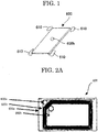
- air bubbles 610 tend to be included in corners of the surrounding area of an inlet 600, when the inlet is mounted by laminating sheets, as illustrated in FIG. 1 .
- the inclusion of the air bubbles at the corners of the surrounding of the inlet 600 may cause surface unevenness of a thermoreversible recording medium, leading to recording and erasure failures as the thermoreversible recording medium is printed by a printer.
- the inlet When an inlet sheet and an adhesive sheet are laminated by a pair of rubber nip rollers, for example, the inlet is nipped with the surfaces of the two nip rollers. As the sheets enter into the space between the nip rollers with the surrounding of the inlet forming a triangle space due to the height of the inlet, and the air included therein, air bubbles are included in a final product. As a diameter of the roller increases, more likely air bubbles are included therein.
- a method for producing an IC card containing: supplying an adhesive from multiple nozzles to apply the adhesive in the form of a plurality of lines on at least part of a surface of an inlet film, a surface of a surface film, or both; laminating the inlet film and the surface film; and compressing the laminate to roll out the adhesive applied in the form of lines, to thereby bond the inlet film with the surface film (see PTL 1).
- the laminate is pressed by a press roller to give a desirable thickness of the adhesive over the entire width.
- the adhesive liquid is dropped on the inlet film from the top while the inlet film is transported, and the sheets are bonded just after air bubbles are included. Therefore, there is a possibility that air bubbles are enclosed at the points where the rolled out adhesive meets with the other.
- thermoreversible recording medium being thin and uniform in total thickness which method enables lamination without inclusion of air bubbles and prevention of recording failure and print failure caused by surface unevenness.
- An object of the present invention is to provide a method for continuously producing with high efficiency a thermoreversible recording medium being thin and uniform in total thickness which method enables lamination without inclusion of air bubbles and prevention of recording failure and print failure caused by surface unevenness.
- the present invention can solve the above-mentioned conventional problems and achieve the above-mentioned object. That is, the present invention can provide a method for continuously producing with high efficiency a thermoreversible recording medium being thin and uniform in total thickness which method enables lamination without inclusion of air bubbles and prevention of recording failure and print failure caused by surface unevenness.
- a method for producing a thermoreversible recording medium of the present invention includes a first sheet production step, a second sheet production step, a lamination step, and a control step; and, if necessary, further includes other steps.
- An apparatus for producing a thermoreversible recording medium of the present invention includes a first sheet production unit, a second sheet production unit, a lamination unit, and a control unit; and, if necessary, further includes other units.
- the method for producing a thermoreversible recording medium of the present invention can be suitably performed using the apparatus for producing a thermoreversible recording medium of the present invention.
- the first sheet production step can be performed using the first sheet production unit.
- the second sheet production step can be performed using the second sheet production unit.
- the lamination step can be performed using the lamination unit.
- the control step can be performed using the control unit.
- the other steps can be performed using the other units.
- the first sheet production step is arranging inlets on a first base sheet to be spaced apart from each other by predetermined intervals to thereby produce a first sheet, where the first sheet has a product portion including the inlets and end portions at both ends of the product portion.
- the first sheet production step is performed using the first sheet production unit.
- the first sheet may be referred to as an "inlet sheet.”
- the inlet sheet is not particularly limited and may be appropriately selected depending on the intended purpose as long as inlets are arranged to be spaced apart from each other by predetermined intervals on the first base sheet.
- the inlet sheet preferably has inlets which are arranged to be spaced apart from each other by predetermined intervals on the base sheet; has the product portion including the inlets and the end portions at both ends of the product portion; has a reversible thermosensitive recording layer on a side of the first base sheet on which no inlet is arranged; and, if necessary, further includes other layers.
- the inlet includes, on a circuit board, a convex-shaped electronic information recording element (hereinafter may be referred to as an "IC portion") and an antenna circuit; and, if necessary, further includes other members.
- IC portion convex-shaped electronic information recording element
- antenna circuit an antenna circuit
- the base material for use in forming the circuit board is not particularly limited and may be appropriately selected depending on the intended purpose.
- Examples of thereof include rigid-type materials such as paper phenol, glass epoxy and composites; flexible-type materials such as polyimides, polyesters, polypropylenes, polyethylenes, polystyrenes, nylon, polyethylene terephthalate (PET), paper and synthetic paper; and complex-type materials of the rigid-type materials and the flexible-type materials.
- the thickness of the base material for use in forming the circuit board is not particularly limited and may be appropriately selected depending on the intended purpose. It is, however, preferably 15 ⁇ m to 360 ⁇ m. Further, from the viewpoints that the thermoreversible recording medium is made thin to improve the flexibility, a base having the electronic information recording element which is lower in height allows the thermoreversible recording medium to be thin, and a base having the circuit board and the antenna circuit which are small in thickness enables making an adhesive layer for covering and coating the base thin and is excellent in processability and cost performance, it is more preferably 15 ⁇ m to 100 ⁇ m.
- the metal foil when a metal foil serving as the antenna circuit is laminated on the base material for use in forming the circuit board, the metal foil is not particularly limited, and a copper foil, an aluminum foil, an iron foil may be used, for example.
- the aluminum foil is preferable for its excellence in costs and processability.
- the thickness thereof is not particularly limited and may be appropriately selected depending on the intended purpose, but is preferably 6 ⁇ m to 50 ⁇ m.
- the shape of the base material for use in forming the circuit board is not particularly limited and may be appropriately selected depending on the intended purpose. For example, a square, a rectangle, a circular shape, and an ellipse shape are exemplified.
- the thickness (height) of the electronic information recording element is not particularly limited and may be appropriately selected depending on the intended purpose. It is, however, preferably 200 ⁇ m or less, and more preferably 25 ⁇ m to 140 ⁇ m.
- a protective film such as a polyimide film, a polyester film, and paper can also be bonded on the electronic information recording element.
- the method for forming the antenna circuit is not particularly limited and may be appropriately selected depending on the intended purpose. Examples of thereof include a method of etching metal films stacked on the circuit board, a method of repeatedly rolling up a covered electric wire (e.g., enamel wire) on the same surface of a base, a method of printing so-called electroconductive paste on the circuit board, a method of embedding the antenna circuit in a base, and a method of laminating a metal foil serving as the antenna circuit.
- a covered electric wire e.g., enamel wire
- the thickness of the protective film is not particularly limited and may be appropriately selected depending on the intended purpose.
- the thickness is preferably 10 ⁇ m to 60 ⁇ m, for example.
- a center-to-center distance (pitch) between adjacent inlets on the inlet sheet is not particularly limited and may be appropriately selected depending on the intended purpose, but is preferably 1 mm to 500 mm, more preferably 1 mm to 300 mm. When the pitch is shorter than 1 mm, air bubbles may be included during lamination, leading to lamination failure.
- a coiled antenna circuit and a capacitative element are formed on a circuit board (e.g., a plastic film) to form an LC resonance circuit, and thereby the inlet can receive a radio wave having a constant frequency as well as transmit and sent back information of an electronic information recording element (IC chip) to its transmission source.
- a circuit board e.g., a plastic film
- a communication frequency generally, it is appropriately selected from frequency bands (e.g., 125 kHz, 13.56 MHz, 2.45 GHz, 5.8 GHz (microwave) and a UHF band) for use.
- frequency bands e.g., 125 kHz, 13.56 MHz, 2.45 GHz, 5.8 GHz (microwave) and a UHF band
- a commercially available product of the inlet sheet is not particularly limited and may be appropriately selected depending on the intended purpose.
- inlets sheets available from, for example, UPM, OMRON, Alien Technology Corporation, Sony Corporation, FUJITSU LIMITED, Hitachi, Ltd., Texas Instruments Incorporated, Fujii Corporation, Dai Nippon Printing Co., Ltd., and TOPPAN PRINTING CO., LTD. can be used.
- the first base sheet is not particularly limited as to its shape, structure and size, and may be appropriately selected depending on the intended purpose.
- the shape include a film shape, and a sheet shape.
- Examples of plane shapes include a square, and a circular shape.
- Examples of the structure include a single-layer structure, and a multi-layered structure. The size may be appropriately selected depending on the intended purpose.
- the first base sheet is not particularly limited and may be appropriately selected depending on the intended purpose.
- the base sheet may be, for example, a resin sheet, a rubber sheet, a synthetic paper, a metal sheet, a glass sheet or a composite thereof. Among them, the resin sheet is particularly preferred.
- a material for forming the resin sheet is not particularly limited and may be appropriately selected depending on the intended purpose.
- examples thereof include polyethylene terephthalate, polycarbonate, polystyrene, and polymethyl methacrylate. These may be used alone or in combination. Among them, polyethylene terephthalate is particularly preferred.
- the first base sheet may be appropriately synthesized or may be a commercially available product.
- the first base sheet usually has concave portions into which the inlets are inserted.
- a method of forming the concave portion in the first base sheet is not particularly limited and may be appropriately selected depending on the intended purpose. Examples thereof include laser processing, micro-mill processing, and perforated board lamination.
- the average thickness of the first base sheet is not particularly limited and may be appropriately selected in view of the depth of the concave portion, if present.
- the thickness is preferably 20 ⁇ m to 300 ⁇ m, and more preferably 50 ⁇ m to 188 ⁇ m.
- the average thickness of the first base sheet is less than 20 ⁇ m, it may be difficult to insert the inlet into the concave portion.
- the thickness of the first base sheet is more than 300 ⁇ m, the thickness of the thermoreversible recording medium is increased, causing lack of flexibility, and it may be difficult to efficiently inserting plural stacked sheets of thermoreversible recording media into a printer.
- the inlet sheet has the product portion including the inlets and end portions at both ends of the product portion.
- the width of the end portions is not particularly limited and may be appropriately selected depending on the intended purpose, but is preferably 2 mm to 300 mm, more preferably 2 mm to 10 mm.
- the reversible thermosensitive recording layer reversibly changes in color tone and contains a reversible thermosensitive recording material reversibly changing in color depending on change in temperature.
- the reversible thermosensitive recording material changes in color as a result of changing in combination, for example, of light transmittance, light reflectance, light absorption wavelength and light scattering degree.
- the reversible thermosensitive recording material is not particularly limited and may be appropriately selected depending on the intended purpose as long as it can reversibly change in transparency or color tone by heat. Examples of thereof include those which turn into a first color at a first temperature higher than ambient temperature and turn into a second color after heating at a second temperature higher than the first temperature and then cooling.
- the reversible thermosensitive recording material which turns into another color at first and second temperatures is particularly preferable.
- Specific examples include a material which becomes transparent at a first temperature and becomes opaque at a second temperature (see Japanese Patent Application Laid-Open ( JP-A) No. 55-154198 ), a material which develops color at a second temperature and becomes colorless at a first temperature (see JP-A Nos. 04-224996 , 04-247985 and 04-267190 ), a material which becomes opaque at a first temperature and becomes transparent at a second temperature (see JP-A No. 03-169590 ), and a material which turns into, for example, black, red, or blue at a first temperature and becomes colorless at a second temperature (see JP-A Nos. 02-188293 and 02-188294 ).
- Particularly preferred are dispersions of an organic low-molecular-weight material (e.g., higher fatty acids) in a base resin; and mixtures of a leuco dye and a color developer.
- the leuco dye is not particularly limited and may be appropriately selected depending on the intended purpose.
- Examples of the leuco dye include phthalide compounds, azaphthalide compounds and fluoran compounds. These may be used alone or in combination.
- the color developer is not particularly limited and may be appropriately selected depending on the intended purpose.
- Examples of the color developer include those disclosed in, for example, JP-A Nos. 05-124360 , 06-210954 and 10-95175 . These may be used alone or in combination.
- the color developer is a compound having, in the molecule thereof, one or more structure allowing a leuco dye to develop color (e.g., a phenolic hydroxyl group, carboxylic acid group and phosphoric acid group) and one or more structure controlling an intermolecular force (e.g., a structure containing a long chain hydrocarbon group).
- a leuco dye e.g., a phenolic hydroxyl group, carboxylic acid group and phosphoric acid group
- an intermolecular force e.g., a structure containing a long chain hydrocarbon group.
- These structures may be linked to each other via a di- or higher polyvalent linking group containing a hetero atom.
- the long chain hydrocarbon group may have such a linking group and/or an aromatic group.
- Examples of such a color developer include those disclosed in, for example, JP-A Nos. 09-290563 and 11-188969 . Among them, preferred is at least one compound selected from compounds represented by the following General Formulas (1) and (2). These color developers have much higher sensitivity than conventional color developers, and thus energy applied for image formation can be reduced by about 10% to about 30%. In this case, thermal decomposition of the color developer can be reduced, and less damage is given to the thermoreversible recording medium and the surface thereof. As a result, durability after repetitive use does not degrade, maintaining excellent image quality.
- X and Y each independently represent a hetero atom-containing divalent organic group
- R 1 represents a substituted or unsubstituted divalent hydrocarbon group
- R 2 represents a substituted or unsubstituted monovalent hydrocarbon group
- a denotes an integer of 1 to 3
- b denotes an integer of 1 to 20
- c denotes an integer of 0 to 3.
- Z represents a hetero atom-containing divalent organic group
- R 3 represents a substituted or unsubstituted divalent hydrocarbon group
- R 4 represents a substituted or unsubstituted monovalent hydrocarbon group
- d denotes an integer of 1 to 3.
- X, Y and Z each independently represent a hetero atom-containing divalent organic group, and preferably represent a nitrogen or oxygen atom-containing divalent organic group; e.g., divalent organic groups containing at least one selected from the groups represented by the following structural formulas.
- hetero atom-containing divalent organic group examples include those represented by the following structural formulas.
- R 1 and R 3 each represent an optionally substituted divalent hydrocarbon group having 1 to 20 carbon atoms.
- Suitable groups represented by R 1 or R 3 include those represented by the following structural formulas : where each of q, q', q" and q'" denotes an integer satisfying the following condition: the total number of carbon atoms contained in the groups represented by R 1 or R 3 is 1 to 20. Among them, groups represented by -(CH 2 ) q - are particularly preferred.
- R 2 and R 4 each represent an optionally substituted aliphatic hydrocarbon group having 1 to 24 carbon atoms, preferably 8 to 18 carbon atoms.
- the aliphatic hydrocarbon group may be linear or branched, and may have an unsaturated bond.
- substituent linked to the hydrocarbon group include a hydroxyl group, a halogen atom and an alkoxy group.
- Suitable groups represented by R 2 or R 4 include those represented by the following structural formulas: where each of q, q', q" and q'" denotes an integer satisfying the following condition: the total number of carbon atoms contained in the groups represented by R 2 or R 4 is 1 to 24. Among them, groups represented by -(CH 2 )q-CH 3 are particularly preferred.
- the reversible thermosensitive recording layer may further contain an additive for improving and/or controlling coating property of a coating liquid therefor and color developability/erasability thereof.
- the additive include surfactants, conductivity-imparting agents, fillers, antioxidants, color development stabilizers and color erasure promoter.
- the reversible thermosensitive recording layer preferably contains a leuco dye, a color developer and an additive together with a binder resin.
- the binder resin is not particularly limited and may be appropriately selected depending on the intended purpose, as long as it can bond the leuco dye, the color developer and the additive onto the base sheet.
- Particularly preferred examples of the binder resin include resins which have been cured using heat, ultraviolet (UV) ray, or electron beam (EB) for improving durability after repetitive use.
- Particularly preferred are thermally-cured resins using a curing agent. These resins can increase a gel ratio of the reversible thermosensitive recording layer.
- the thermally-curable resin is not particularly limited and may be appropriately selected depending on the intended purpose.
- examples of the thermally-curable resin include acryl polyol resins, polyester polyol resins, polyurethane polyol resins, polyvinyl butyral resins, cellulose acetate propionate and cellulose acetate butyrate.
- the curing agent is not particularly limited and may be appropriately selected depending on the intended purpose.
- isocyanates are used.
- the isocyanate include hexamethylene diisocyanate (HDI), tolylene diisocyanate (TDI), xylylene diisocyanate (XDI) and isophorone diisocyanate (IPDI); an adduct type, burette type, or isocyanurate type formed between, for example, trimethylolpropane and the above isocyanates; and blocked products of the above isocyanates.
- HDI hexamethylene diisocyanate
- TDI tolylene diisocyanate
- XDI xylylene diisocyanate
- IPDI isophorone diisocyanate
- an adduct type, burette type, or isocyanurate type formed between, for example, trimethylolpropane and the above isocyanates and blocked products of the above isocyanates.
- the reversible thermosensitive recording layer is not particularly limited and may be appropriately selected depending on the intended purpose, but preferably has a gel ratio of 30% or higher, more preferably 50% or higher, further preferably 70% or higher. When the gel ratio is lower than 30%, the reversible thermosensitive layer may exhibit degraded durability after repetitive use.
- the mass of components other than the binder resin e.g., particles of organic low-molecular-weight materials
- the mass of particles of organic low-molecular-weight materials is not previously obtained, it may be calculated from a mass ratio of the binder resin to the particles of organic low-molecular-weight materials.
- the mass ratio can be determined based on their specific gravities and a ratio of an area occupied with the binder resin to that occupied with the particles of organic low-molecular-weight materials obtained by observing a unit area of the cross portion of the layer through, for example, a transmission electron microscopy (TEM) or a scanning electron microscopy (SEM).
- TEM transmission electron microscopy
- SEM scanning electron microscopy
- a mass ratio of the binder resin to a chromogenic component is not particularly limited and may be appropriately selected depending on the intended purpose, but is preferably 0.1 to 10. When the mass ratio is less than 0.1, the formed reversible thermosensitive recording layer has insufficient heat resistance; whereas when the mass ratio is more than 10, the density of color developed may decrease.
- the reversible thermosensitive recording layer can be formed through application of a coating liquid prepared by homogeneously dispersing, in a solvent, a leuco dye, a color developer, an additive and a binder resin.
- the solvent is not particularly limited and may be appropriately selected depending on the intended purpose. Examples thereof include alcohols, ketones, ethers, glycol ethers, esters, aromatic hydrocarbons and aliphatic hydrocarbons.
- the coating liquid can be prepared using a disperser such as a paint shaker, a ball mill, an attriter, a three-roll mill, a Kady mill, a sand mill, a Dino mill or a colloid mill.
- a disperser such as a paint shaker, a ball mill, an attriter, a three-roll mill, a Kady mill, a sand mill, a Dino mill or a colloid mill.
- the coating liquid may be prepared by dispersing the above materials in a solvent using a disperser or may be mixing dispersions of the above materials one another. Also, these materials are dissolved in a solvent under heating and then the solution is rapidly or slowly cooled for precipitation.
- Examples of application methods for forming the reversible thermosensitive recording layer include a blade coating, a wire bar coating, a spray coating, an air knife coating, a bead coating, a curtain coating, a gravure coating, a kiss coating, a reverse roll coating, a dip coating or a die coating.
- the average thickness of the reversible thermosensitive recording layer is not particularly limited and may be appropriately selected depending on the intended purpose. It is preferably 1 ⁇ m to 20 ⁇ m, more preferably 3 ⁇ m to 15 ⁇ m. When the average thickness is less than 1 ⁇ m, the density of color developed may decrease to degrade the contrast of the formed image. Whereas when the average thickness is more than 20 ⁇ m, position-dependent variation in the amount of heat applied becomes large in the reversible thermosensitive recording layer. Some portions of the recording layer do not develop color since the temperature of the portions does not reach a color developing temperature, potentially resulting in failure to attain a desired color density.
- the reversible thermosensitive recording layer is not particularly limited, may be provided on the first base sheet before the lamination of the inlets with the first base sheet, or may be provided on the first base sheet after the lamination of the inlets with the first base sheet.
- Examples of other layers include a under layer, an intermediate layer and a protective layer.
- Example of a production method of the inlet sheet includes a method in which concave portions are formed on the first base sheet by means of laser, machining, engraving, or perforated board lamination, and then IC portions of the inlets are inserted into the concave portions (antenna ICs (i.e., convex portions) are inserted into counterbores (i.e., concave portions)) to thereby laminate together.
- concave portions are formed on the first base sheet by means of laser, machining, engraving, or perforated board lamination, and then IC portions of the inlets are inserted into the concave portions (antenna ICs (i.e., convex portions) are inserted into counterbores (i.e., concave portions)) to thereby laminate together.
- the second sheet production step is applying an adhesive onto a second base sheet using an adhesive application unit, to produce a second sheet, and the second sheet production step is performed using the second sheet production unit.
- the second sheet may be referred to as an "adhesive sheet.”
- the second base sheet used for the second sheet may be the same as the first base sheet.
- the average thickness of the second base sheet in the second sheet is not particularly limited and may be appropriately selected depending on the intended purpose, but is preferably 20 ⁇ m to 300 ⁇ m, more preferably 50 ⁇ m to 188 ⁇ m.
- An adhesive material in the adhesive is not particularly limited and may be appropriately selected depending on the intended purpose.
- the adhesive material include urea resins, melamine resins, phenol resins, epoxy resins, vinyl acetate resins, vinyl acetate-acrylic copolymers, ethylene-vinyl acetate copolymers, acrylic resins, polyvinyl ether resins, vinyl chloride-vinyl acetate copolymers, polystyrene resins, polyester resins, polyurethane resins, polyamide resins, chlorinated polyolefin resins, polyvinyl butyral resins, acrylic acid ester copolymers, methacrylic acid ester copolymers, natural rubbers, synthetic rubbers, cyanoacrylate resins, silicone resins, styrene-isoprene-styrene block copolymers and ethylene-vinyl acetate copolymers (EVA).
- acrylic resins preferred are natural rubbers, synthetic rubbers, acrylic resins, silicone resins, polyurethane resins, styrene-isoprene-styrene block copolymers and ethylene-vinyl acetate copolymers (EVA), with acrylic resins being particularly preferable.
- the adhesive is preferably a wet-curable type adhesive which discharges carbon dioxide gas when cured in wetness.
- a wet-curable type adhesive when voids including moisture and air are present between an inlet and an adhesive sheet, carbon dioxide gas is generated, and the surface of the resulting thermoreversible recording medium swells. As a result, a thermoreversible recording medium having a smooth surface cannot be obtained. Such generation of bubbles continues for approximately three days and therefore the surface configuration of the recording medium greatly changes.
- the adhesive may be a commercially available product.
- Example of thereof includes PUR-HM adhesive PERFECT LOCK series (product of Henkel Technologies Japan Ltd.)
- the adhesive is applied onto the second base sheet using the adhesive application unit.
- the adhesive application unit is not particularly limited and may be appropriately selected depending on the intended purpose.
- Example thereof includes a dispenser.
- the adhesive application unit is preferably provided in an upstream of a gap between a pair of gap rollers.
- the average thickness of the adhesive layer is not particularly limited and may be appropriately selected depending on the intended purpose. However, provided that when the same thickness as that from the bottom surface of the base of the electronic information recording portion to a plane of the antenna circuit (the thickness of an antenna portion) is defined as +0 ⁇ m, the average thickness of the adhesive layer is preferably +0 ⁇ m to +280 ⁇ m, more preferably +0 ⁇ m to +100 ⁇ m, and particularly preferably +0 ⁇ m to 60 ⁇ m. When the average thickness of the adhesive layer is less than that of the antenna portion, the thickness uniformity of the resulting thermoreversible recording medium is insufficient, and the print quality degrades.
- the adhesive layer when the adhesive layer is formed to have a thickness exceeding +150 ⁇ m relative to 100 ⁇ m in thickness of the antenna portion so that a total thickness exceeds 250 ⁇ m, the adhesive layer is melted by heat pressure from a thermal head, and an adhesive liquid pool may overflow into the end portions when printing or erasing is performed on the thermoreversible recording medium using a heater.
- the width of the adhesive sheet (second sheet), to which the adhesive is applied is not particularly limited and may be appropriately selected depending on the intended purpose, but is preferably 70% to 100% relative to the width of the product portion on the inlet sheet (first sheet).
- the lamination portions at the ends of the sheets may not be completely filled with the adhesive liquid regardless of viscosity or inlet inclusion/lamination unless the adhesive liquid pool is controlled.
- a surface level of the adhesive to be spread is unstably moved up and down to form a thin space as the laminate is passed through the nip between the gap rollers, and therefore unexpected oval-shaped air bubbles tend to be included.
- An adhesive sheet with such air bubble defect forms only a slight deformation, and therefore it is very difficult to detect by a defect detecting device, and therefore there is a possibility that a product having such defect may be brought into a market without being detected.
- the applied width is 70% or more, on the other hand, the space between the gap rollers can be stably filled with the adhesive by controlling the spread of the adhesive liquid pool by bead controlling, and therefore oval-shaped air bubbles are not included.
- the viscosity of the adhesive is not particularly limited and may be appropriately selected depending on the intended purpose. However, at lamination temperature, it is preferably 10,000 cps to 100,000 cps, more preferably 20,000 cps to 70,000 cps from the viewpoint of preventing a displacement of the inlet during passing through a gap between a pair of gap rollers due to low viscosity.
- the viscosity of the adhesive When the viscosity of the adhesive is less than 10,000 cps, the adhesive easily flows, and thus, the adhesive liquid pool (bead) rapidly spreads laterally Therefore, the amount of the adhesive to be applied should be adjusted sensitively and rapidly.
- the viscosity of the adhesive is less than 10,000 cps, the adhesive liquid pool cannot be formed on the periphery of the inlet.
- the inlet moves to thereby cause a displacement. Additionally, larger end portions are required because the bead excessively spreads.
- the viscosity of the adhesive is related to the temperature and is determined based on a curve representing a relationship between viscosities and temperatures of an adhesive. Therefore, the viscosity of the adhesive should be controlled by temperature control.
- an antistatic electroconductive filler is preferably contained in the adhesive layer.
- the antistatic electroconductive filler is contained so as to prevent double feed in a printer due to sticking, and improve processing of stacking thermoreversible recording media.
- the antistatic electroconductive filler is not particularly limited and may be appropriately selected depending on the intended purpose. Examples thereof include an inorganic filler and an organic filler.
- Examples of the inorganic filler include carbonates, silicates, metal oxides and sulfuric acid compounds.
- organic filler examples include silicone resins, cellulose resins, epoxy resins, nylon resins, phenol resins, polyurethane resins, urea resins, melamine resins, polyesters, polycarbonates, styrene resins, acrylic resins, polyethylenes, formaldehyde resins and polymethyl methacrylates.
- the lamination step is passing the first sheet and the second sheet through a gap between a pair of gap rollers in the manner that the inlets and the adhesive face to each other to laminate the first sheet with the second sheet, while forming an adhesive liquid pool in an upstream of the gap.
- the lamination step is performed using the lamination unit.
- the method for laminating the inlet sheet with the adhesive sheet is not particularly limited.
- an adhesive may applied to the inlet sheet, and thereby the inlet sheet can be laminated with the adhesive sheet.
- an adhesive be applied to the adhesive sheet to thereby perform the lamination.
- the adhesive can be applied to the entire surface of the adhesive sheet, however, the adhesive is preferably selectively applied.
- thermoreversible recording medium Employing gap rollers rather than nip rollers in the lamination step allows the total thickness of the thermoreversible recording medium to be uniform due to a possibility of minor adjustment in thickness.
- the first sheet is preferably laminated with the second sheet at 60°C to 100°C.
- the viscosity of the adhesive is controlled to fall within a range from 10,000 cps to 100,000 cps, which can prevent a displacement of the inlets during passing through between the gap rollers.
- the thickness of the adhesive liquid pool is preferably thicker than the thickness of the adhesive upon application on the second base sheet and the thickness of the adhesive between the pair of gap rollers.
- the length in height direction (thickness) of the adhesive liquid pool formed during passing the inlet sheet and the adhesive sheet through the gap between the gap rollers is thicker than an average thickness of the inlets, is preferably 10 times or more as thick as the average thickness of the inlets, and is more preferably 300 ⁇ m to 5 mm.
- a material of the gap roller is not particularly limited and may be appropriately selected depending on the intended purpose, as long as it has high surface hardness. However, it is preferably metal.
- Example thereof includes stainless steel (e.g., SUS 304).
- the surface hardness HV of the gap roller is not particularly limited and may be appropriately selected depending on the intended purpose, but is preferably 180 or more.
- a thermoreversible recording medium which is a finished product
- a thermoreversible recording medium is affected in the total thickness and surface unevenness due to a concavo-convex shape of the inlet.
- a nip roller regardless of material (e.g., a metal roller, a rubber roller or a resin roller)
- a thermoreversible recording medium, which is a finished product is affected by nip pressure in the total thickness and surface unevenness due to a concavo-convex shape of the inlet.
- the surface hardness HV is measured by a method using a square pyramid-shaped diamond indenter, which is one of indentation hardness test methods.
- the indenter is according to JIS B7725.
- a roller diameter of the gap roller is not particularly limited and may be appropriately selected depending on the intended purpose, but is preferably 80 mm to 250 mm.
- the transfer speed at which the inlet sheet and the adhesive sheet are transferred into between the gap rollers is not particularly limited and may be appropriately selected depending on the intended purpose. It is preferably 1 m/min to 100 m/min, and more preferably 2 m/min to 10 m/min.
- the conveyance control (speed) easily varies.
- the transfer speed is higher than 100 m/min, the precision of width-direction aligning of the sheet may degrade.
- the control step is feedback controlling an amount of the adhesive to be applied in the applying so that the adhesive liquid pool does not flow into the end portions on the first sheet; and is performed using the control unit.
- control step contain detecting the adhesive liquid pool by a sensor, and increasing the amount of the adhesive to be applied by the adhesive application unit in the applying in the case where the adhesive liquid pool does not reach the end portions of the first sheet and spreads within the product portion, or decreasing the amount of the adhesive to be applied by the adhesive application unit in the applying in the case where the adhesive liquid pool flow over the product portion into the end portions on the first sheet.
- the senor examples include a single point laser displacement sensor, a straight line-shaped two-dimensional displacement sensor, an imaging camera sensor and an infrared temperature detection sensor.
- the imaging camera sensor is preferred.
- Example of the imaging camera includes a CCD camera.
- the adhesive liquid pool is prevented from being spread into the end portions, and it is possible to continuously produce a thermoreversible recording medium with controlling an applied width of the adhesive to be constant.
- an applied amount of the adhesive is set to be an excessive amount relative to an amount required for one product to accumulate the adhesive, which forms an adhesive liquid pool.
- a sensor which detects both left and right edges of the adhesive liquid pool from the front side that faces the adhesive liquid pool. Using the sensor, positions of the left and right edges (left and right end portions) of the adhesive liquid pool are detected.
- the information obtained by the sensor is feedback to an inverter of a gear pump to increase or decrease the amount of the adhesive to be applied with increasing or decreasing the rotational speed of the pump, so as not to spread the adhesive liquid pool into the end portions. In this manner, the size of the adhesive liquid pool is repeatedly increased or degreased, to thereby perform the bead control (see FIG. 6 ).
- FIG. 6 is a diagram illustrating one example of the feedback control (bead control) of the adhesive liquid pool.
- the left edge (left end portion), right edge (right portion), and height of the adhesive liquid pool are detected by a CCD camera serving as an image sensor from the upstream side to judge the necessity of an increase or decrease in the ejection amount of the adhesive.
- a rotational speed of a gear pump is increased via an inverter.
- the rotational speed of the gear pump is decreased via the inverter.
- the overflow width of the adhesive liquid pool was measured both in the case where the control for the adhesive liquid pool (bead control) was performed, and the case where the bead control was not performed.
- the results are presented in FIG. 7 .
- an adhesive liquid pool 105 is formed between a pair of gap rollers, which are accurately regulated with an inlet sheet 103 and an adhesive sheet 104 to give a target total thickness, as illustrated in FIGs. 4A to 4C , and 5 .
- the inlet sheet 103 and the adhesive sheet 104 are passed through a pair of the gap rollers, the inlet 102 is enclosed by the adhesive liquid pool 105 without including air bubbles therein. Moreover, the inlet is passed through a pair of the gap roller while the inlet gradually pushes air bubbles against the surface of the adhesive liquid pool 105 the amount of which are controlled to be constant.
- thermoreversible recording medium of the present invention leveling by passing the inlet sheet 103 and the adhesive sheet 104 through between a pair of the gap roller, and control for the adhesive liquid pool are performed. Specifically, the adhesive in the more amount than necessary is provided between a pair of the gap roller, and the sheets are passed through between the rollers maintaining a uniform gap to level front and back surfaces, to thereby provide a thermoreversible recording medium having uniform smoothness and total thickness.
- the start up time can be significantly reduced.
- high speed start can be achieved within 5 minutes without affecting a uniformity of a film thickness of an adhesive to be applied.
- thermoreversible recording medium is produced by the method for producing a thermoreversible recording medium of the present invention, and includes inlets each of which has a convex-shaped electronic information recording element and an antenna circuit on a circuit board, a reversible thermosensitive recording layer, and a base sheet including a plurality of concave portions on a surface thereof opposite to a surface thereof on which the reversible thermosensitive recording layer is provided, wherein the convex-shaped electronic information recording element is laminated so as to be inserted into the concave portion.
- the total thickness of the resultant thermoreversible recording medium is not particularly limited and may be appropriately selected depending on the intended purpose, but is preferably 350 ⁇ m to 410 ⁇ m. In-plane thickness variation in a front surface and a back surface of the thermoreversible recording medium is preferably 25 ⁇ m or less.
- FIG. 2A is a schematic plan view illustrating one example of an inlet
- FIG. 2B is a schematic side view of the inlet illustrated in FIG. 2A .
- a coiled antenna circuit 600c and a capacitative element are formed on a circuit board 600a (e.g., a plastic film) to form an LC resonance circuit, and thereby the inlet 600 can receive a radio wave having a constant frequency as well as transmit and sent back information of an electronic information recording element (IC chip) 600b to its transmission source.
- a circuit board 600a e.g., a plastic film
- FIG. 3 is a cross-sectional view illustrating one example of a thermoreversible recording medium producedaccording to the present invention.
- thermoreversible recording medium 1 in FIG. 3 includes a reversible thermosensitive recording layer 3, a first base sheet 2 provided adjacent to the reversible thermosensitive recording layer 3, an inlet 7 having a convex-shaped IC portion 7b and an antenna circuit 7c on a circuit board 7a, and an adhesive 5 provided for bonding the first base sheet 2 and the IC portion 7b.
- a concave portion 6 is formed on a surface thereof opposite to a surface thereof on which the reversible thermosensitive recording layer 3 is provided.
- the inlet 7 is arranged so that the IC portion 7b is inserted into the concave portion 6 in the first base sheet 2.
- thermoreversible recording medium 1 With use of the thermoreversible recording medium 1, a close contact with the thermoreversible recording medium 1 is easily performed when the thermoreversible recording medium 1 is pressed against the members such as a thermal head, an erasure bar, an erasure roller, and an erasure plate in an image printing/erasure process by making the thermoreversible recording medium 1 thin and flexible. As a result, it is possible to eliminate nonuniformity of contact from the top surface of the recording medium by a thermal head or erasure bar and nonuniformity of contact from the bottom surface thereof by a platen roller., and it is also possible to accept the profile irregularity of the thermal head without causing coloring nonuniformity and erasure nonuniformity caused by contact failure to thereby stabilize the print quality.
- the IC portion 7b is inserted into the concave portion 6 of the first base sheet 2, a step difference or unevenness caused by the IC portion 7b can be eliminated, and thereby the print quality can be improved.
- the inlet No. 1 shown in Table 1 (product of ALIEN) was used in this Example.
- Concave portions for inserting the IC portions were formed in 2 mm square at a center portion in one surface of a polyethylene-telephthalate (PET) resin base sheet with a thickness of 100 ⁇ m, which is served as a first base sheet.
- An adhesive (produced by Henkel Technologies Japan Ltd., PUR-HM adhesive PURMELT QR9504) was applied to an area including the concave portions so as to have a thickness of 20 ⁇ m.
- a reversible thermosensitive recording layer with a thickness of 36 ⁇ m is formed on a side of the first base sheet on which no concave portion was arranged.
- An adhesive sheet was prepared by applying, with a dispenser, the adhesive (product of Henkel Technologies Japan Ltd., PUR-HM adhesive PURMELT R9504) to a polyethylene-telephthalate (PET) resin sheet with a thickness of 100 ⁇ m which is served as the second base sheet so as to have the thickness of 20 ⁇ m.
- PET polyethylene-telephthalate
- PUR-HM adhesive PURMELT R9504 a polyethylene-telephthalate
- the adhesive was applied onto a smooth second base sheet.
- thermoreversible recording medium No. 1 an amount of the adhesive to be applied was not controlled upon lamination so as to keep an adhesive liquid pool formed between the pair of the gap rollers at a constant amount (without bead control).
- thermoreversible recording media No. 2 and No. 3 were obtained in the same manner as in No. 1, provided that the inlet No. 1 (product of ALIEN) was changed to inlets No. 2 and No. 3 as depicted in Table 1. Notably, for the thermoreversible recording media No. 2 and No. 3, an amount of the adhesive to be applied was not controlled upon lamination so as to keep an adhesive liquid pool formed between the pair of the gap rollers at a constant amount (without bead control).
- Thermoreversible Recording Media No. 4 to No. 17 were obtained in the same manner as in No. 1, provided that the inlet No. 1 (product of ALIEN) was changed to inlets No. 4 to No. 17 asdepicted in Table 1 and the bead control was performed as described below.
- the inlet sheet was laminated with the adhesive sheet by passing through the pair of gap rollers while keeping an adhesive liquid pool formed between the pair of the gap rollers at a constant amount and gradually removing bubbles from the inlet at a wall surface of the adhesive liquid pool (with bead control).
- the bead control is performed by detecting a left edge portion (left end portion), a right edge portion (right end portion) and height of the adhesive liquid pool using a CCD color camera as a sensor and feedback-controlling.
- FIG. 8 is a photograph of a pair of the gap rollers, at which the bead control is stably performed, taken by a CCD color camera from the upstream side.
- the left and right edge portions of the adhesive liquid pool are recognized in the CCD camera image in which there are gloss portions in the center, and the black portions at the left and right edges, and therefore the presence of the adhesive liquid pool can be visually recognized.
- the gradation (gray area) present in between was provided with a threshold changing a standard density depending on a type of the adhesive.
- a threshold changing a standard density depending on a type of the adhesive.
- the left edge portion and the right edge portion of the adhesive liquid pool were determined by the CCD camera image processing software so that the 50% gradation area became the left and right edge portions (left and right end portions).
- the area that is within 5 mm from the right edge, i.e., from the right edge to X was determined as the right end portion.
- the height of the adhesive liquid pool could be clearly detected as the eight of the gloss portion in FIG. 8 . Therefore, the length of the up-down line (height) of the gloss portion was determined by the CCD camera image processing software, and the obtained value was determined as the height of the adhesive liquid pool. In FIG. 8 , the height of the center of the adhesive liquid pool was 3,200 ⁇ m.
- the left edge portion (left end portion, right edge portion (right end portion), and height of the adhesive liquid pool (S5) were detected by the sensor (S1).
- the adhesive liquid pool (S5) exceeded the maximum limit of the left and right edges (exceeded the end portions)
- the rotational speed of the gear pump was decreased via the inverter (S3) (e.g., reducing the rotational speed from 28% to 25%) to reduce the ejected amount of the adhesive by the adhesion applying unit.
- the left and right edge portions of the adhesive liquid pool were dark in the CCD camera image. Note that, in the case where it cannot be visually observed, spreading of the adhesive liquid pool is caused.
- the spreading width of the adhesive liquid pool was controlled within the range of the end portions (5 mm from the edge) as illustrated in FIG. 7 .
- thermoreversible recording media No. 1 to No. 17 were evaluated for various properties as follows. The results are shown in Table 1.
- thermoreversible recording media were visually observed by transmitting light emitted from a fluorescent lamp through the media, and the presence and size of bubbles in the surrounding area of the inlet were measured with a scale (vernier caliper) and evaluated according to the following criteria.
- thermoreversible recording media were visually observed by transmitting light emitted from a fluorescent lamp through the media, and the presence and size of air bubbles in the surrounding area of the inlet were measured with a scale (vernier caliper).
- the size of the air bubbles and the edge size thereof in the surrounding area of the antenna were measured, compared with that of immediately after the lamination, and evaluated according to the following criteria.
- the thickness A of areas provided with an inlet and the thickness B of areas provided with no inlet were measured with a micrometer (product of Mitsutoyo K.K., 389-251), and a difference (A - B) in thickness therebetween was determined as a surface unevenness value.
- the thickness A and thickness B were average thicknesses of any 10 or more measurement positions. As the surface unevenness value is smaller, the surface is flatter. An acceptance criterion of the surface unevenness value in the present invention is 15 ⁇ m or less. Table 1-1-1 No.
- Thickness of base Thickness of antenna portion Thickness of chip portion Step Difference of chip portion Thickness of swage portion 1 51 ⁇ m 55 ⁇ m 265 ⁇ m 210 ⁇ m - 2 81 ⁇ m 105 ⁇ m 301 ⁇ m 196 ⁇ m - 3 43 ⁇ m 73 ⁇ m 249 ⁇ m 176 ⁇ m 139 ⁇ m 4 41 pm 71 ⁇ m 253 pm 170 ⁇ m 235 ⁇ m 5 54 ⁇ m 68 ⁇ m 235 ⁇ m 167 ⁇ m 205 ⁇ m 6 43 ⁇ m 73 ⁇ m 246 ⁇ m 163 ⁇ m 187 ⁇ m 7 43 ⁇ m 73 ⁇ m 249 pm 176 ⁇ m 139 ⁇ m 8 62 ⁇ m 80 ⁇ m 248 ⁇ m 168 ⁇ m - 9 63 ⁇ m 80 ⁇ m 251 ⁇ m 171 ⁇ m - 10 61 ⁇ m 79 pm 250 ⁇ m 171
- Diameter : 3,4 mm (number of bubbles: 8) B 650 ⁇ m 413 ⁇ m 237 ⁇ m 3 C
- thermoreversible recording medium An inlet sheet and an adhesive sheet were bonded together to produce a thermoreversible recording medium in the same manner as in Example 1, provided that a type and viscosity of the adhesive, lamination temperature, and to perform or not to perform the bead control were changed as depicted in Table 2. Note that, AD-631 (manufactured by AVERY) of No. 2 of Table 1 was used as the inlet, and the bead control was performed in the same manner as in Example 1.
- thermoreversible recording medium The various properties of the obtained thermoreversible recording medium were evaluated in the following manner. The results are presented in Table 2.
- the viscosity of the adhesive liquid was measured by means of a viscometer (HADV-IIPro, manufactured by Brookfield Engineering Laboratories) at the lamination temperature.
- Whether or not the position of the spread adhesive liquid was controlled depending on performing or not performing the bead control was determined by the aforementioned detecting method of the left edge and right edge portions of the adhesive liquid pool, and the results were evaluated based on the following criteria.
- An adhesive (20 ⁇ m in thickness) was applied as a base of an inlet on a back surface of a base sheet of each of the produced thermoreversible recording media, and the position of the inlet was marked with the inlet bonded on the adhesive. After passing through between gap rollers together with a base via the adhesive liquid pool to bond the base sheet with the base, how much the inlet was displaced from the marked position after the bonding was measured using a scale (a caliper). The degree of the displacement was evaluated based on the following criteria.
- thermoreversible recording media In the case where irregularities could not be visually observed on a surface of each of the produced thermoreversible recording media, a total thickness of the inlet bonded portion was measured by clamping the front and back surfaces of the thermoreversible recording medium by means of a micrometer (389-251, manufactured by Mitutoyo Corporation) the measuring surfaces of which were flat surfaces having a diameter of 5 mm, and the results were evaluated based on the following criteria.
- Inlet sheets were produced in the same manner as in Example 1, provided that center-to-center distances (pitches) between adjacent inlets were changed to 300 mm, 100 mm, 10 mm, 5 mm, 3 mm, 2 mm and 1 mm.
- thermoreversible recording media were produced by laminating the adhesive sheets produced in Example 1 with the inlet sheets in the same manner as in Example 1, except that the following conditions were used. Notably, upon lamination, the bead control was performed in the same manner as in Example 1.
- Thermoreversible recording media were produced by laminating the adhesive sheets with the inlet sheets in the same manner as in Example 1, provided that conditions shown in Table 4 and the following experimental conditions were used. Notably, upon lamination, the bead control was performed in the same manner as in Example 1.
- the adhesive having the viscosity of 24,000 cps or less at the lamination temperature of 80°C may cause a displacement of the inlet unless there is a sufficient gap (+75 ⁇ m or more) on the inlet, as the inlet placed in the middle of the inlet sheet and the adhesive sheet is pushed off by the gap of the gap rollers. Moreover, the inlet may be displaced by the flow of the adhesive for pushing out the excess adhesive to form the adhesive liquid pool.
- thermoreversible recording medium of the present invention can suitably used for production of a thermoreversible recording medium having an inlet, because they enable to bond the inlet and a convex-shaped electronic information recording element together without including air bubbles, to prevent recording and printing failures of a thermoreversible recording medium due to a contact failure with a flat printing head (metal surface), which is caused due to a minute surface distortion of several tens micrometers, to continuously produce a thermoreversible recording medium at high efficiency, and to produce a thermoreversible recording medium of various size.
- a flat printing head metal surface
- the method of the present invention can be widely applied for bonding of sheets, other than the production of a thermoreversible recording medium, because a total adjustment start up time can be shortened in each step, which usually requires a long time due to complexity of bonding of sheets without including air bubbles in a surrounding area of an inlet, and due to complexity of operations to give uniformity of a total thickness within the plane of a sheet product obtained by bonding, without depending on the adjustment of an ejection amount of an adhesive on the sheet to give a uniform film thickness.
Landscapes
- Engineering & Computer Science (AREA)
- Physics & Mathematics (AREA)
- Computer Hardware Design (AREA)
- Microelectronics & Electronic Packaging (AREA)
- General Physics & Mathematics (AREA)
- Theoretical Computer Science (AREA)
- Manufacturing & Machinery (AREA)
- Health & Medical Sciences (AREA)
- Chemical & Material Sciences (AREA)
- Chemical Kinetics & Catalysis (AREA)
- General Chemical & Material Sciences (AREA)
- General Health & Medical Sciences (AREA)
- Toxicology (AREA)
- Heat Sensitive Colour Forming Recording (AREA)
- Credit Cards Or The Like (AREA)
- Fluid Mechanics (AREA)
Claims (8)
- Procédé permettant de produire un support d'enregistrement thermoréversible (1), comprenant les étapes consistant à :Agencer, sur une première feuille de base (2, 103), des entrées (7, 102) en les espaçant les unes des autres par des intervalles prédéterminés afin de produire ainsi une première feuille, ladite première feuille présentant une partie produit comprenant les entrées (7, 102) et des parties extrémité au niveau des deux extrémités de la partie produit ;appliquer un adhésif (5) sur une deuxième feuille de base (104) en utilisant une unité d'application d'adhésif, afin de produire une deuxième feuille ;faire passer la première feuille et la deuxième feuille à travers un espace situé entre une paire de rouleaux à écartement (101a, 101b) de telle manière que les entrées (7, 102) et l'adhésif (5) se font face afin de laminer la première feuille avec la deuxième feuille, tout en formant une réserve de liquide adhésif (105) en amont dudit espace ; etcommander par rétroaction une quantité de l'adhésif (5) à appliquer lors de l'étape d'application, de sorte que la réserve de liquide adhésif (105) ne s'écoule pas jusqu'aux parties extrémité de la première feuille.
- Procédé selon la revendication 1, dans lequel l'étape de commande par rétroaction comprend une étape consistant à détecter la réserve de liquide adhésif (105) grâce à un capteur, et augmenter la quantité de l'adhésif (5) à appliquer grâce à l'unité d'application d'adhésif lors de l'étape d'application dans le cas où la réserve de liquide adhésif (105) n'atteint pas les parties extrémité de la première feuille et se répand au sein de la partie produit, ou diminuer la quantité de l'adhésif (5) à appliquer grâce à l'unité d'application d'adhésif lors de l'étape d'application dans le cas où la réserve de liquide adhésif (105) s'écoule par-dessus la partie produit jusqu'aux parties extrémité sur la première feuille.
- Procédé selon la revendication 2, dans lequel le capteur est un capteur de déplacement à laser monopoint, un capteur linéaire de déplacement bidimensionnel, un capteur à caméra d'imagerie, ou un capteur infrarouge de détection de température.
- Procédé selon l'une quelconque des revendications 1 à 3, dans lequel une viscosité de l'adhésif (5) est comprise entre 10 000 cps et 100 000 cps à une température permettant le laminage.
- Procédé selon l'une quelconque des revendications 1 à 4, dans lequel la première feuille est laminée avec la deuxième feuille entre 60°C et 100°C.
- Procédé selon l'une quelconque des revendications 1 à 5, dans lequel une distance de centre à centre entre les entrées (7, 102) adjacentes sur la première feuille est comprise entre 1 mm et 500 mm.
- Procédé selon l'une quelconque des revendications 1 à 6, dans lequel une largeur sur laquelle l'adhésif (5) est appliqué sur la deuxième feuille est comprise entre 70% et 100% d'une largeur de la partie produit de la première feuille.
- Appareil permettant de produire un support d'enregistrement thermoréversible (1), comprenant :une unité de production de première feuille configurée pour agencer, sur une première feuille de base (103), des entrées (102) à espacer les unes des autres par des intervalles prédéterminés afin de produire ainsi une première feuille présentant une partie produit comprenant les entrées (102) et des parties extrémité au niveau des deux extrémités de la partie produit ;une unité de production de deuxième feuille configurée pour appliquer un adhésif sur une deuxième feuille de base (104) en utilisant une unité d'application d'adhésif, afin de produire une deuxième feuille ;une unité de laminage configurée pour faire passer la première feuille et la deuxième feuille à travers un espace situé entre une paire de rouleaux à écartement (101a, 101b) de telle manière que les entrées (102) et l'adhésif se font face afin de laminer la première feuille avec la deuxième feuille, tout en formant une réserve de liquide adhésif (105) en amont dudit espace ; etune unité de commande configurée pour commander par rétroaction une quantité de l'adhésif à appliquer lors de l'étape d'application, de sorte que la réserve de liquide adhésif (105) ne s'écoule pas jusqu'aux parties extrémité sur la première feuille.
Applications Claiming Priority (2)
| Application Number | Priority Date | Filing Date | Title |
|---|---|---|---|
| JP2012064654A JP6051554B2 (ja) | 2012-03-22 | 2012-03-22 | 熱可逆記録媒体の製造方法及びその製造装置 |
| PCT/JP2013/058185 WO2013141327A1 (fr) | 2012-03-22 | 2013-03-14 | Procédé pour la production d'un support d'enregistrement thermoréversible et appareil pour la production d'un tel support |
Publications (3)
| Publication Number | Publication Date |
|---|---|
| EP2748773A1 EP2748773A1 (fr) | 2014-07-02 |
| EP2748773A4 EP2748773A4 (fr) | 2015-12-23 |
| EP2748773B1 true EP2748773B1 (fr) | 2017-02-08 |
Family
ID=49222780
Family Applications (1)
| Application Number | Title | Priority Date | Filing Date |
|---|---|---|---|
| EP13764381.3A Not-in-force EP2748773B1 (fr) | 2012-03-22 | 2013-03-14 | Procédé pour la production d'un support d'enregistrement thermoréversible et appareil pour la production d'un tel support |
Country Status (8)
| Country | Link |
|---|---|
| US (1) | US9283799B2 (fr) |
| EP (1) | EP2748773B1 (fr) |
| JP (1) | JP6051554B2 (fr) |
| KR (1) | KR20140083043A (fr) |
| CN (1) | CN103946875B (fr) |
| MX (1) | MX2014006029A (fr) |
| TW (1) | TWI488756B (fr) |
| WO (1) | WO2013141327A1 (fr) |
Families Citing this family (2)
| Publication number | Priority date | Publication date | Assignee | Title |
|---|---|---|---|---|
| WO2016186712A1 (fr) * | 2015-05-15 | 2016-11-24 | Dow Global Technologies Llc | Système d'apport de matériau pour machine à contrecoller |
| US9626754B2 (en) * | 2015-05-28 | 2017-04-18 | Jabil Circuit, Inc. | System, apparatus and method for dispensed adhesive material inspection |
Family Cites Families (17)
| Publication number | Priority date | Publication date | Assignee | Title |
|---|---|---|---|---|
| JP2000067199A (ja) * | 1998-08-18 | 2000-03-03 | Oji Paper Co Ltd | Icカードおよびその製造方法 |
| JP3520205B2 (ja) * | 1998-09-18 | 2004-04-19 | 株式会社 日立インダストリイズ | ペースト塗布方法とペースト塗布機 |
| JP2002163619A (ja) * | 2000-11-22 | 2002-06-07 | Sony Corp | Icカード |
| JP3868332B2 (ja) | 2002-05-23 | 2007-01-17 | トッパン・フォームズ株式会社 | Icタグラミネート装置および方法 |
| JP2004209810A (ja) | 2002-12-27 | 2004-07-29 | Konica Minolta Holdings Inc | 積層体の製造方法及び積層体の製造装置 |
| JP2005174161A (ja) | 2003-12-15 | 2005-06-30 | Konica Minolta Photo Imaging Inc | Icカード及びicカードの製造方法 |
| JP2005339462A (ja) | 2004-05-31 | 2005-12-08 | Konica Minolta Photo Imaging Inc | Icカード及びicカードの製造方法 |
| JP2006007153A (ja) * | 2004-06-29 | 2006-01-12 | Konica Minolta Photo Imaging Inc | 接着剤塗布装置、接着剤塗布方法、電子情報記録カードの製造装置及び電子情報記録カードの製造方法 |
| JP2006178566A (ja) | 2004-12-21 | 2006-07-06 | Konica Minolta Photo Imaging Inc | Icカード作製方法、icカード作製装置及びicカード |
| JP2006192799A (ja) | 2005-01-14 | 2006-07-27 | Ricoh Co Ltd | 可逆性感熱記録媒体 |
| KR101257120B1 (ko) | 2005-01-28 | 2013-04-22 | 가부시끼가이샤 이테크 | Ic 카드 제조용 접착제, ic 카드의 제조 방법 및 ic카드 |
| JP2007156589A (ja) * | 2005-12-01 | 2007-06-21 | Konica Minolta Medical & Graphic Inc | 電子情報記録カードの製造方法及び電子情報記録カードの製造装置 |
| JP5229107B2 (ja) * | 2009-05-20 | 2013-07-03 | 大日本印刷株式会社 | Icカードの製造方法及びicカードの製造システム |
| EP2264652B1 (fr) | 2009-06-09 | 2016-06-01 | Ricoh Company, Ltd. | Support d'enregistrement d'informations thermosensible et son procédé de fabrication |
| KR101012242B1 (ko) | 2010-02-03 | 2011-02-08 | 김지수 | 전분 수지가 함침된 한지시트를 이용한 카드 및 그 제작방법 |
| JP5672067B2 (ja) * | 2010-03-09 | 2015-02-18 | 株式会社リコー | 可逆性感熱記録媒体の製造方法及び製造装置、並びに可逆性感熱記録媒体 |
| JP5924017B2 (ja) | 2011-02-16 | 2016-05-25 | 株式会社リコー | 可逆性感熱記録媒体及びその製造方法 |
-
2012
- 2012-03-22 JP JP2012064654A patent/JP6051554B2/ja not_active Expired - Fee Related
-
2013
- 2013-03-14 WO PCT/JP2013/058185 patent/WO2013141327A1/fr not_active Ceased
- 2013-03-14 KR KR1020147013632A patent/KR20140083043A/ko not_active Ceased
- 2013-03-14 EP EP13764381.3A patent/EP2748773B1/fr not_active Not-in-force
- 2013-03-14 US US14/345,370 patent/US9283799B2/en not_active Expired - Fee Related
- 2013-03-14 MX MX2014006029A patent/MX2014006029A/es active IP Right Grant
- 2013-03-14 CN CN201380003858.7A patent/CN103946875B/zh not_active Expired - Fee Related
- 2013-03-19 TW TW102109713A patent/TWI488756B/zh not_active IP Right Cessation
Non-Patent Citations (1)
| Title |
|---|
| None * |
Also Published As
| Publication number | Publication date |
|---|---|
| US9283799B2 (en) | 2016-03-15 |
| KR20140083043A (ko) | 2014-07-03 |
| MX2014006029A (es) | 2014-07-11 |
| JP6051554B2 (ja) | 2016-12-27 |
| CN103946875B (zh) | 2017-02-22 |
| EP2748773A1 (fr) | 2014-07-02 |
| JP2013193389A (ja) | 2013-09-30 |
| CN103946875A (zh) | 2014-07-23 |
| TWI488756B (zh) | 2015-06-21 |
| US20150005161A1 (en) | 2015-01-01 |
| WO2013141327A1 (fr) | 2013-09-26 |
| EP2748773A4 (fr) | 2015-12-23 |
| TW201402354A (zh) | 2014-01-16 |
Similar Documents
| Publication | Publication Date | Title |
|---|---|---|
| EP2365466B1 (fr) | Procédé de production d'un support d'enregistrement thermosensible, appareil de production correspondant et support d'enregistrement thermosensible réversible | |
| EP2490157B1 (fr) | Support d'enregistrement d'informations thermosensible et son procédé de fabrication | |
| EP2264652B1 (fr) | Support d'enregistrement d'informations thermosensible et son procédé de fabrication | |
| EP2077188B1 (fr) | Support d'enregistrement thermosensible réversible | |
| KR100605054B1 (ko) | 카드의 제조방법 | |
| EP2748773B1 (fr) | Procédé pour la production d'un support d'enregistrement thermoréversible et appareil pour la production d'un tel support | |
| JP4838558B2 (ja) | 無線情報記録媒体 | |
| RU2575816C1 (ru) | Способ изготовления термообратимого носителя записи и устройство для изготовления такого носителя | |
| US7405180B2 (en) | Wireless information recording medium | |
| JP2011018318A (ja) | 可逆性感熱記録媒体 | |
| JP2011154673A (ja) | 可逆性感熱記録媒体及びその製造方法 | |
| EP3608842B1 (fr) | Carte ayant une structure en relief |
Legal Events
| Date | Code | Title | Description |
|---|---|---|---|
| PUAI | Public reference made under article 153(3) epc to a published international application that has entered the european phase |
Free format text: ORIGINAL CODE: 0009012 |
|
| 17P | Request for examination filed |
Effective date: 20140324 |
|
| AK | Designated contracting states |
Kind code of ref document: A1 Designated state(s): AL AT BE BG CH CY CZ DE DK EE ES FI FR GB GR HR HU IE IS IT LI LT LU LV MC MK MT NL NO PL PT RO RS SE SI SK SM TR |
|
| DAX | Request for extension of the european patent (deleted) | ||
| RA4 | Supplementary search report drawn up and despatched (corrected) |
Effective date: 20151119 |
|
| RIC1 | Information provided on ipc code assigned before grant |
Ipc: B41M 5/337 20060101ALI20151130BHEP Ipc: B32B 41/00 20060101ALI20151130BHEP Ipc: B41M 5/30 20060101ALI20151130BHEP Ipc: G06K 19/07 20060101ALI20151130BHEP Ipc: B32B 37/12 20060101ALI20151130BHEP Ipc: B42D 15/00 20060101ALI20151130BHEP Ipc: G06K 19/077 20060101AFI20151130BHEP |
|
| GRAP | Despatch of communication of intention to grant a patent |
Free format text: ORIGINAL CODE: EPIDOSNIGR1 |
|
| INTG | Intention to grant announced |
Effective date: 20160823 |
|
| GRAS | Grant fee paid |
Free format text: ORIGINAL CODE: EPIDOSNIGR3 |
|
| GRAA | (expected) grant |
Free format text: ORIGINAL CODE: 0009210 |
|
| AK | Designated contracting states |
Kind code of ref document: B1 Designated state(s): AL AT BE BG CH CY CZ DE DK EE ES FI FR GB GR HR HU IE IS IT LI LT LU LV MC MK MT NL NO PL PT RO RS SE SI SK SM TR |
|
| REG | Reference to a national code |
Ref country code: GB Ref legal event code: FG4D |
|
| REG | Reference to a national code |
Ref country code: CH Ref legal event code: EP Ref country code: AT Ref legal event code: REF Ref document number: 867166 Country of ref document: AT Kind code of ref document: T Effective date: 20170215 |
|
| REG | Reference to a national code |
Ref country code: IE Ref legal event code: FG4D |
|
| REG | Reference to a national code |
Ref country code: FR Ref legal event code: PLFP Year of fee payment: 5 |
|
| REG | Reference to a national code |
Ref country code: DE Ref legal event code: R096 Ref document number: 602013017330 Country of ref document: DE |
|
| REG | Reference to a national code |
Ref country code: LT Ref legal event code: MG4D |
|
| REG | Reference to a national code |
Ref country code: NL Ref legal event code: MP Effective date: 20170208 |
|
| REG | Reference to a national code |
Ref country code: AT Ref legal event code: MK05 Ref document number: 867166 Country of ref document: AT Kind code of ref document: T Effective date: 20170208 |
|
| PG25 | Lapsed in a contracting state [announced via postgrant information from national office to epo] |
Ref country code: HR Free format text: LAPSE BECAUSE OF FAILURE TO SUBMIT A TRANSLATION OF THE DESCRIPTION OR TO PAY THE FEE WITHIN THE PRESCRIBED TIME-LIMIT Effective date: 20170208 Ref country code: LT Free format text: LAPSE BECAUSE OF FAILURE TO SUBMIT A TRANSLATION OF THE DESCRIPTION OR TO PAY THE FEE WITHIN THE PRESCRIBED TIME-LIMIT Effective date: 20170208 Ref country code: NO Free format text: LAPSE BECAUSE OF FAILURE TO SUBMIT A TRANSLATION OF THE DESCRIPTION OR TO PAY THE FEE WITHIN THE PRESCRIBED TIME-LIMIT Effective date: 20170508 Ref country code: GR Free format text: LAPSE BECAUSE OF FAILURE TO SUBMIT A TRANSLATION OF THE DESCRIPTION OR TO PAY THE FEE WITHIN THE PRESCRIBED TIME-LIMIT Effective date: 20170509 Ref country code: FI Free format text: LAPSE BECAUSE OF FAILURE TO SUBMIT A TRANSLATION OF THE DESCRIPTION OR TO PAY THE FEE WITHIN THE PRESCRIBED TIME-LIMIT Effective date: 20170208 |
|
| PG25 | Lapsed in a contracting state [announced via postgrant information from national office to epo] |
Ref country code: NL Free format text: LAPSE BECAUSE OF FAILURE TO SUBMIT A TRANSLATION OF THE DESCRIPTION OR TO PAY THE FEE WITHIN THE PRESCRIBED TIME-LIMIT Effective date: 20170208 Ref country code: SE Free format text: LAPSE BECAUSE OF FAILURE TO SUBMIT A TRANSLATION OF THE DESCRIPTION OR TO PAY THE FEE WITHIN THE PRESCRIBED TIME-LIMIT Effective date: 20170208 Ref country code: PT Free format text: LAPSE BECAUSE OF FAILURE TO SUBMIT A TRANSLATION OF THE DESCRIPTION OR TO PAY THE FEE WITHIN THE PRESCRIBED TIME-LIMIT Effective date: 20170608 Ref country code: LV Free format text: LAPSE BECAUSE OF FAILURE TO SUBMIT A TRANSLATION OF THE DESCRIPTION OR TO PAY THE FEE WITHIN THE PRESCRIBED TIME-LIMIT Effective date: 20170208 Ref country code: RS Free format text: LAPSE BECAUSE OF FAILURE TO SUBMIT A TRANSLATION OF THE DESCRIPTION OR TO PAY THE FEE WITHIN THE PRESCRIBED TIME-LIMIT Effective date: 20170208 Ref country code: AT Free format text: LAPSE BECAUSE OF FAILURE TO SUBMIT A TRANSLATION OF THE DESCRIPTION OR TO PAY THE FEE WITHIN THE PRESCRIBED TIME-LIMIT Effective date: 20170208 Ref country code: BG Free format text: LAPSE BECAUSE OF FAILURE TO SUBMIT A TRANSLATION OF THE DESCRIPTION OR TO PAY THE FEE WITHIN THE PRESCRIBED TIME-LIMIT Effective date: 20170508 Ref country code: ES Free format text: LAPSE BECAUSE OF FAILURE TO SUBMIT A TRANSLATION OF THE DESCRIPTION OR TO PAY THE FEE WITHIN THE PRESCRIBED TIME-LIMIT Effective date: 20170208 |
|
| PG25 | Lapsed in a contracting state [announced via postgrant information from national office to epo] |
Ref country code: IT Free format text: LAPSE BECAUSE OF FAILURE TO SUBMIT A TRANSLATION OF THE DESCRIPTION OR TO PAY THE FEE WITHIN THE PRESCRIBED TIME-LIMIT Effective date: 20170208 Ref country code: CZ Free format text: LAPSE BECAUSE OF FAILURE TO SUBMIT A TRANSLATION OF THE DESCRIPTION OR TO PAY THE FEE WITHIN THE PRESCRIBED TIME-LIMIT Effective date: 20170208 Ref country code: SK Free format text: LAPSE BECAUSE OF FAILURE TO SUBMIT A TRANSLATION OF THE DESCRIPTION OR TO PAY THE FEE WITHIN THE PRESCRIBED TIME-LIMIT Effective date: 20170208 Ref country code: EE Free format text: LAPSE BECAUSE OF FAILURE TO SUBMIT A TRANSLATION OF THE DESCRIPTION OR TO PAY THE FEE WITHIN THE PRESCRIBED TIME-LIMIT Effective date: 20170208 Ref country code: RO Free format text: LAPSE BECAUSE OF FAILURE TO SUBMIT A TRANSLATION OF THE DESCRIPTION OR TO PAY THE FEE WITHIN THE PRESCRIBED TIME-LIMIT Effective date: 20170208 |
|
| REG | Reference to a national code |
Ref country code: CH Ref legal event code: PL |
|
| REG | Reference to a national code |
Ref country code: DE Ref legal event code: R097 Ref document number: 602013017330 Country of ref document: DE |
|
| PG25 | Lapsed in a contracting state [announced via postgrant information from national office to epo] |
Ref country code: SM Free format text: LAPSE BECAUSE OF FAILURE TO SUBMIT A TRANSLATION OF THE DESCRIPTION OR TO PAY THE FEE WITHIN THE PRESCRIBED TIME-LIMIT Effective date: 20170208 Ref country code: MC Free format text: LAPSE BECAUSE OF FAILURE TO SUBMIT A TRANSLATION OF THE DESCRIPTION OR TO PAY THE FEE WITHIN THE PRESCRIBED TIME-LIMIT Effective date: 20170208 Ref country code: DK Free format text: LAPSE BECAUSE OF FAILURE TO SUBMIT A TRANSLATION OF THE DESCRIPTION OR TO PAY THE FEE WITHIN THE PRESCRIBED TIME-LIMIT Effective date: 20170208 Ref country code: PL Free format text: LAPSE BECAUSE OF FAILURE TO SUBMIT A TRANSLATION OF THE DESCRIPTION OR TO PAY THE FEE WITHIN THE PRESCRIBED TIME-LIMIT Effective date: 20170208 |
|
| PLBE | No opposition filed within time limit |
Free format text: ORIGINAL CODE: 0009261 |
|
| STAA | Information on the status of an ep patent application or granted ep patent |
Free format text: STATUS: NO OPPOSITION FILED WITHIN TIME LIMIT |
|
| REG | Reference to a national code |
Ref country code: IE Ref legal event code: MM4A |
|
| 26N | No opposition filed |
Effective date: 20171109 |
|
| PG25 | Lapsed in a contracting state [announced via postgrant information from national office to epo] |
Ref country code: LU Free format text: LAPSE BECAUSE OF NON-PAYMENT OF DUE FEES Effective date: 20170314 |
|
| PG25 | Lapsed in a contracting state [announced via postgrant information from national office to epo] |
Ref country code: SI Free format text: LAPSE BECAUSE OF FAILURE TO SUBMIT A TRANSLATION OF THE DESCRIPTION OR TO PAY THE FEE WITHIN THE PRESCRIBED TIME-LIMIT Effective date: 20170208 Ref country code: CH Free format text: LAPSE BECAUSE OF NON-PAYMENT OF DUE FEES Effective date: 20170331 Ref country code: LI Free format text: LAPSE BECAUSE OF NON-PAYMENT OF DUE FEES Effective date: 20170331 Ref country code: IE Free format text: LAPSE BECAUSE OF NON-PAYMENT OF DUE FEES Effective date: 20170314 |
|
| REG | Reference to a national code |
Ref country code: BE Ref legal event code: MM Effective date: 20170331 |
|
| REG | Reference to a national code |
Ref country code: FR Ref legal event code: PLFP Year of fee payment: 6 |
|
| PG25 | Lapsed in a contracting state [announced via postgrant information from national office to epo] |
Ref country code: BE Free format text: LAPSE BECAUSE OF NON-PAYMENT OF DUE FEES Effective date: 20170331 |
|
| PG25 | Lapsed in a contracting state [announced via postgrant information from national office to epo] |
Ref country code: MT Free format text: LAPSE BECAUSE OF NON-PAYMENT OF DUE FEES Effective date: 20170314 |
|
| PG25 | Lapsed in a contracting state [announced via postgrant information from national office to epo] |
Ref country code: HU Free format text: LAPSE BECAUSE OF FAILURE TO SUBMIT A TRANSLATION OF THE DESCRIPTION OR TO PAY THE FEE WITHIN THE PRESCRIBED TIME-LIMIT; INVALID AB INITIO Effective date: 20130314 |
|
| PG25 | Lapsed in a contracting state [announced via postgrant information from national office to epo] |
Ref country code: CY Free format text: LAPSE BECAUSE OF NON-PAYMENT OF DUE FEES Effective date: 20170208 |
|
| PG25 | Lapsed in a contracting state [announced via postgrant information from national office to epo] |
Ref country code: MK Free format text: LAPSE BECAUSE OF FAILURE TO SUBMIT A TRANSLATION OF THE DESCRIPTION OR TO PAY THE FEE WITHIN THE PRESCRIBED TIME-LIMIT Effective date: 20170208 |
|
| PG25 | Lapsed in a contracting state [announced via postgrant information from national office to epo] |
Ref country code: TR Free format text: LAPSE BECAUSE OF FAILURE TO SUBMIT A TRANSLATION OF THE DESCRIPTION OR TO PAY THE FEE WITHIN THE PRESCRIBED TIME-LIMIT Effective date: 20170208 |
|
| PG25 | Lapsed in a contracting state [announced via postgrant information from national office to epo] |
Ref country code: AL Free format text: LAPSE BECAUSE OF FAILURE TO SUBMIT A TRANSLATION OF THE DESCRIPTION OR TO PAY THE FEE WITHIN THE PRESCRIBED TIME-LIMIT Effective date: 20170208 Ref country code: IS Free format text: LAPSE BECAUSE OF FAILURE TO SUBMIT A TRANSLATION OF THE DESCRIPTION OR TO PAY THE FEE WITHIN THE PRESCRIBED TIME-LIMIT Effective date: 20170608 |
|
| PGFP | Annual fee paid to national office [announced via postgrant information from national office to epo] |
Ref country code: FR Payment date: 20210323 Year of fee payment: 9 |
|
| PGFP | Annual fee paid to national office [announced via postgrant information from national office to epo] |
Ref country code: GB Payment date: 20210324 Year of fee payment: 9 Ref country code: DE Payment date: 20210319 Year of fee payment: 9 |
|
| REG | Reference to a national code |
Ref country code: DE Ref legal event code: R119 Ref document number: 602013017330 Country of ref document: DE |
|
| GBPC | Gb: european patent ceased through non-payment of renewal fee |
Effective date: 20220314 |
|
| PG25 | Lapsed in a contracting state [announced via postgrant information from national office to epo] |
Ref country code: GB Free format text: LAPSE BECAUSE OF NON-PAYMENT OF DUE FEES Effective date: 20220314 Ref country code: FR Free format text: LAPSE BECAUSE OF NON-PAYMENT OF DUE FEES Effective date: 20220331 Ref country code: DE Free format text: LAPSE BECAUSE OF NON-PAYMENT OF DUE FEES Effective date: 20221001 |