EP2748832B1 - Lampe à décharge à haute pression - Google Patents
Lampe à décharge à haute pression Download PDFInfo
- Publication number
- EP2748832B1 EP2748832B1 EP12808898.6A EP12808898A EP2748832B1 EP 2748832 B1 EP2748832 B1 EP 2748832B1 EP 12808898 A EP12808898 A EP 12808898A EP 2748832 B1 EP2748832 B1 EP 2748832B1
- Authority
- EP
- European Patent Office
- Prior art keywords
- housing
- burner
- lamp
- cap
- electrical contact
- Prior art date
- Legal status (The legal status is an assumption and is not a legal conclusion. Google has not performed a legal analysis and makes no representation as to the accuracy of the status listed.)
- Active
Links
Images
Classifications
-
- H—ELECTRICITY
- H01—ELECTRIC ELEMENTS
- H01J—ELECTRIC DISCHARGE TUBES OR DISCHARGE LAMPS
- H01J61/00—Gas-discharge or vapour-discharge lamps
- H01J61/02—Details
- H01J61/36—Seals between parts of vessels; Seals for leading-in conductors; Leading-in conductors
-
- H—ELECTRICITY
- H01—ELECTRIC ELEMENTS
- H01J—ELECTRIC DISCHARGE TUBES OR DISCHARGE LAMPS
- H01J5/00—Details relating to vessels or to leading-in conductors common to two or more basic types of discharge tubes or lamps
- H01J5/50—Means forming part of the tube or lamps for the purpose of providing electrical connection to it
- H01J5/54—Means forming part of the tube or lamps for the purpose of providing electrical connection to it supported by a separate part, e.g. base
-
- H—ELECTRICITY
- H01—ELECTRIC ELEMENTS
- H01J—ELECTRIC DISCHARGE TUBES OR DISCHARGE LAMPS
- H01J61/00—Gas-discharge or vapour-discharge lamps
- H01J61/02—Details
- H01J61/52—Cooling arrangements; Heating arrangements; Means for circulating gas or vapour within the discharge space
-
- H—ELECTRICITY
- H01—ELECTRIC ELEMENTS
- H01J—ELECTRIC DISCHARGE TUBES OR DISCHARGE LAMPS
- H01J61/00—Gas-discharge or vapour-discharge lamps
- H01J61/82—Lamps with high-pressure unconstricted discharge having a cold pressure > 400 Torr
-
- H—ELECTRICITY
- H01—ELECTRIC ELEMENTS
- H01J—ELECTRIC DISCHARGE TUBES OR DISCHARGE LAMPS
- H01J9/00—Apparatus or processes specially adapted for the manufacture, installation, removal, maintenance of electric discharge tubes, discharge lamps, or parts thereof; Recovery of material from discharge tubes or lamps
- H01J9/24—Manufacture or joining of vessels, leading-in conductors or bases
Definitions
- High-pressure gas discharge lamps are used in a large area of applications where high luminous flux is required. Especially in the automotive field, high-pressure gas discharge lamps are used in vehicle headlights.
- US 2004/0066150 A1 describes a gas-discharge lamp base with an ignition device.
- the base comprises as three main component parts an upper housing part, a lead frame and a cover.
- the upper housing part has a central stub for receiving leads to the lamp burner.
- the lead frame is connected to the lamp burner.
- the lower housing part comprises a covering plate and a cylindrical, hollow, downwardly open hollow cylinder or stub, which is formed on to the plate.
- the electrical conductors are welded or soldered to a printed circuit board or lead frame.
- the lower housing part is inserted with its stub into the upper housing part, such that the stub encloses a high voltage contact of the burner and forms a labyrinth to avoid flashovers.
- the lamp unit comprises a burner including a discharge vessel where an electrical arc may be generated.
- the burner will have two electrical contact leads, such that each of two electrodes may be supplied with electrical power.
- a first electrical contact lead which may also be referred to as a central contact lead, extends preferably from the discharge vessel, and is preferably at least partially guided within a burner tube extending from the discharge vessel.
- a second electrical contact lead, or return contact is preferably provided in parallel to the burner and partially enclosed in a ceramic tube.
- the burner may comprise further a transparent outer bulb provided around the discharge vessel.
- the burner protrudes from a lamp cap housing such that the discharge vessel is arranged at a distance from the housing.
- the burner is fixed to the lamp cap housing, such that at least a first of the electrical contact leads is arranged within the housing.
- parts of a burner in particular a quartz tube provided around an electrical contact lead, may be arranged to extend into the housing, such as e.g. more than half and further preferred even more than two thirds of the axial length of the housing.
- the electrical circuit comprises components required for generating a lamp operating current with a desired waveform and values for electrical current, voltage and power.
- a corresponding driver circuit may comprise semiconductor components for switching a supply voltage to obtain a desired operating voltage in a controlled manner.
- the driver circuit may comprise a microcontroller to control the lamp operation.
- the metallic bottom plate comprises an opening, into which a cap element made out of an insulating material, such as preferably a plastic material, is inserted to enclose at least the first contact lead.
- the invention combines reliable insulation of at least the first contact lead with effective heat dissipation, while maintaining easy assembly. Due to the insulation and heat dissipation, the lamp unit may be made very compact without increasing the risk of electrical flashover or inadmissible operating temperature. By providing an opening in the bottom plate and inserting a cap element, the lamp unit may be easily assembled.
- the cap element may have any shape suitable to at least partially enclose the first contact lead.
- the cap element comprises a bottom section and at least a first enclosing wall structure.
- the bottom section may e.g. be flat and may preferably lie flush with the outer surface of the bottom plate.
- the wall structure preferably extends from the bottom section in axial direction of the lamp unit, preferably at least substantially perpendicular to the outer surface of the bottom section.
- the wall structure may preferably be closed around the first contact, e.g. providing, in cross-section, a closed structure surrounding the first electrical contact lead to all sides.
- the cap element comprises at least a first and a second enclosing wall structure.
- the first enclosing wall structure is preferably arranged to enclose the first contact lead at smaller distance
- the second enclosing wall structure is arranged around the first enclosing wall structure, so as to surround the first contact at a larger distance.
- Providing a plurality of such wall structures one within the other serves to increase the insulation length. While it is possible to provide at least two enclosing wall structures of the same axial length, it have proven advantageous to provide the first wall structure with a smaller and the second wall structure with a greater axial length.
- a corresponding cap element may provide sufficient mounting space close to the first contact lead.
- the cap element extends axially into the housing to at least partially surround (in cross-section) a burner tube extending from the burner into the housing.
- the burner tube is preferably of quartz glass material, and most preferably provided in one piece with the wall of the discharge vessel.
- a first, central contact lead from the burner is arranged within the burner tube.
- the cap element is preferably arranged such that at least a part of a wall structure thereof is arranged between the central contact lead and the return contact lead. In particular during ignition, flashover within the lamp cap housing between the contact leads may thus be avoided.
- the cap element has a bottom comprised of a first bottom section (axially) covering the central contact lead and a second bottom section covering the return contact lead.
- the first bottom section is larger than the second bottom section and is arranged centrally, and the second bottom section is arranged directly bordering on the first bottom section.
- a carrier in particular a printed circuit board, is arranged directly on the bottom plate, such that good thermal contact is achieved.
- the bottom plate serves effectively as heat sink for electrical components on the carrier.
- the carrier is a substantially flat printed circuit board sandwiched on the bottom plate.
- the cap element may be held in place in different ways, such as e.g. by welding, gluing or other fixing measures.
- the holding structures may comprise lamella elements or other shapes, such that during insertion of the cap element into the cavity, the holding structures and/or the cap element is deformed leading to the holding force.
- a burner is fixed to a lamp cap housing and a lamp operating circuit is provided within the housing.
- a bottom plate of the housing is made out of a metal material to dissipate heat.
- a cap is inserted into an opening in the bottom plate and encloses the a first contact lead from the burner.
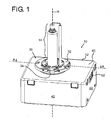
- Fig. 1 shows a lamp unit 10 including a lamp cap housing 12, from which a burner 14 protrudes.
- the burner 14 is comprised of a burner tube 16 forming a discharge vessel 18 with an enclosed discharge space and an outer bulb 20 arranged around the discharge vessel 18.
- the outer bulb 20 and the burner tube 16 with the discharge vessel 18 are made of quartz glass material.
- a first and second electrode are provided within the discharge space.
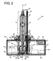
- a first electrode which is electrically connected to a first, central contact lead 22 extending within the burner tube 16 into the housing 12.
- a second electrode is connected to a return contact lead 24 extending in parallel to the longitudinal axis X of the burner 14.
- a ceramic tube 26 is arranged around the return contact lead 24.
- the burner 14 is mechanically held relative to the lamp cap housing 12 by a holding section 30, including a holding ring structure 32 provided around the burner 14, fixed to a collar 34 of the burner 14 by spot-welded spring tongues 36.
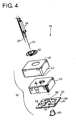
- the lamp cap housing 12 comprises an upper housing cover 40, side walls 42 and a bottom plate 44 as lower housing cover. All of the housing wall elements 40, 42, 44 are made out of aluminum as a metal material of good heat conduction properties.
- the lamp operating circuit 50 is supplied with electrical power from an electrical connector 52 opening to the side of the lamp cap housing 12.
- the lamp unit 10 is electrically connected to onboard electrical power via connector 52.
- the lamp operating circuit 50 integrated within the lamp cap housing 12 provides all circuitry required to adapt the voltage supplied at connector 52 to the type of electrical driving voltage and current required for the operation of the burner 14 during ignition, following run-up and steady-state operation.
- the lamp operating circuit 50 comprises on a printed circuit board 58 circuitry for ignition of the lamp such as a transformer 54 as well as a microcontroller 56 for controlling an alternating current to the burner 14.
- the burner 14 is arranged to protrude quite a distance axially along the axis X into the lamp cap housing 12.
- the burner tube 16 extends over more than half of the axial length of the lamp cap housing 12.
- the result of the corresponding arrangement of the burner 14 quite deep within the lamp cap housing 12 leads to a reduced light center length (LCL), i.e. distance between the center of the discharge vessel 18 relative to the holding ring 32 comprising position reference element for relative positioning within a reflector of a motor vehicle headlight unit.
- LCL light center length
- the electrical contact leads from the burner 14, namely the central contact lead 22 and return contact lead 24, also extend into the lamp cap housing 12 well more than half of the axial distance, and, in the preferred example shown, even over more than 2/3 of the axial length thereof.
- insulation needs to be provided to prevent flashover between the electrical contact leads 22, 24 as well as from any of the contact leads 22, 24 to components or contact leads of the lamp operating circuit 50 or parts of the lamp cap housing 12.
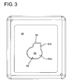
- a plastic cap 60 including a bottom part 62 comprised of a first bottom section 62a covering the central contact lead 22 and a second bottom section 62b covering the return contact lead 24 axially.
- the first bottom section of the cap 60 is larger and arranged substantially centrally to the longitudinal axis X, whereas the second bottom section 62b is smaller and arranged to the side.
- the cap 60 comprises a first enclosing wall structure 64 provided directly around the central contact 22, such that the contact 22, seen in a cross-section perpendicular to the longitudinal axis X, is fully enclosed by the wall structure 64.
- the cap 60 further comprises a second wall structure 66, which extends axially further than the first enclosing wall structure, up to about half of the longitudinal length of the lamp cap housing 12.
- the cap 60 thus serves to provide electrical insulation, in particular between the central contact lead 22 and return contact lead 24, but also between the contact leads 22, 24 and the metal bottom plate 44.
- the lamp operating circuit 50 is arranged on a printed circuit board 58 provided within the lamp cap housing 12, holding and electrically interconnecting the circuit components.
- the printed circuit board (PCB) 58 with the electrical components of a lamp operating circuit 50 mounted on a top surface is arranged directly on the bottom plate 44.
- PCB printed circuit board
- An insulating plastic insert 43 is provided within the lamp cap housing 12 to accommodate the connector 52 and to guide and hold the protruding parts of the burner 14 and return contact 24.
- the insert 43 also comprises vertical plastic walls 45, visible in Fig. 2 , forming an opening 68 for the cap 60.
- the printed circuit board 58 comprises a central opening 68 to accommodate the burner tube 16 with the enclosed central contact lead 22 therein.
- the carrier and the components 54, 56 of the lamp operating circuit 50 are arranged around the opening, and - after assembly - arranged around the burner tube 16 extending through the opening.
- a very compact arrangement with a short LCL is achieved.
- the cap 60 is arranged within a cavity, where the wall structures 64, 66 enter into fitting grooves. These grooves provide lamella-shaped holding structures 70.
- the cap 60 is driven into the cavity with force, such that the wall structure 66 and the holding structures 70 deform to thereafter provide a holding force fixing the cap 60 in place.
- the housing elements of the lamp cap housing 12 which are shown in the embodiment as flat surfaces, may be shaped differently to e.g. comprise heat dissipation structures, such as heat fins etc.
Landscapes
- Engineering & Computer Science (AREA)
- Manufacturing & Machinery (AREA)
- Common Detailed Techniques For Electron Tubes Or Discharge Tubes (AREA)
- Arrangement Of Elements, Cooling, Sealing, Or The Like Of Lighting Devices (AREA)
- Fastening Of Light Sources Or Lamp Holders (AREA)
- Non-Portable Lighting Devices Or Systems Thereof (AREA)
Claims (12)
- Unité de lampe à décharge de gaz à haute pression (10), comprenant- un brûleur (14) avec un récipient à décharge (18), ledit brûleur (14) comprenant des conducteurs de contact électriques (22, 24),- un logement de culot de lampe (12), où ledit brûleur (14) fait saillie à partir dudit logement (12) et est fixé à celui-ci, de sorte qu'au moins un premier desdits conducteurs de contact (22, 24) s'étende dans ledit logement (12),- où un circuit de fonctionnement de lampe (50) est agencé à l'intérieur dudit logement (12), connecté électriquement auxdits conducteurs de contact électriques (22, 24),- où ledit logement (12) comprend une plaque de fond (44) composée d'un matériau métallique pour dissiper de la chaleur,- et où ladite plaque de fond (44) comprend une ouverture (68) dans laquelle un élément de culot (60) composé d'un matériau électriquement isolant est inséré pour enceindre ledit premier conducteur de contact électrique (22).
- Unité selon la revendication 1, où- ledit élément de culot (60) comprend un fond (62) et au moins une première structure de paroi enceignante (64, 66).
- Unité selon une des revendications précédentes, où- ledit élément de culot (60) comprend une première structure de paroi enceignante (64) et une seconde structure de paroi enceignante (66) agencée autour de ladite première structure de paroi enceignante (64).
- Unité selon la revendication 3, où- ladite seconde structure de paroi enceignante (66) possède une longueur axiale plus importante que celle de ladite première structure de paroi enceignante (64).
- Unité selon une des revendications précédentes, où- ledit brûleur (14) comprend un tube de brûleur agencé axialement (16) s'étendant dans ledit logement (12),- où un conducteur de contact central (22) est agencé à l'intérieur dudit tube de brûleur (16),- et où ledit élément de culot (60) s'étend axialement dans ledit logement (12) afin d'entourer au moins partiellement ledit tube de brûleur (16).
- Unité selon une des revendications précédentes, où- ledit brûleur (14) comprend un conducteur de contact central (22) et un conducteur de contact de retour (24),- où au moins une partie d'une structure de paroi (64, 66) dudit culot (60) est agencée entre ledit conducteur de contact central (22) et ledit conducteur de contact de retour (24).
- Unité selon une des revendications précédentes, où- ledit élément de culot (60) comprend une première section de fond (62a) couvrant un conducteur de contact central (22) et un second élément de fond (62b) couvrant un conducteur de contact de retour (24).
- Unité selon une des revendications précédentes, où- ledit circuit de fonctionnement de lampe (50) comprend des composants électrique (54, 56) agencés sur un support(58),- où une ouverture (68) est prévue à l'intérieur dudit support (58), de sorte que ledit conducteur de contact électrique (22) s'étende à travers ladite ouverture (68).
- Unité selon une des revendications précédentes, où- ledit circuit de fonctionnement de lampe (50) comprend des composants électrique (54, 56) agencés sur un support (58),- où ledit support (58) est agencé directement sur ladite plaque de fond (44).
- Unité selon une des revendications précédentes, où- ledit logement comprend une cavité dans laquelle ledit élément de culot (60) est reçu,- où ledit élément de culot (60) est retenu à l'intérieur de ladite cavité par des structures de retenue (70) appuyant contre ledit élément de culot (60).
- Logement de culot de lampe (12) pour une unité de lampe à décharge de gaz à haute pression (10), comprenant :- un espace pour recevoir un brûleur (14) avec un récipient à décharge (18) et des conducteurs de contact électriques (22, 24) de sorte que ledit brûleur (14) fasse saillie à partir dudit logement (12),- un espace pour recevoir au moins un premier desdits conducteurs de contact (22, 24), de sorte qu'il s'étende dans ledit logement (12),- un espace pour agencer un circuit de fonctionnement de lampe (50) agencé à l'intérieur dudit logement (12) pour être connecté électriquement auxdits conducteurs de contact électriques (22, 24),- où ledit logement (12) comprend une plaque de fond (44) composée d'un matériau métallique pour dissiper de la chaleur,- et où ladite plaque de fond (44) comprend une ouverture (68) dans laquelle un élément de culot (60) composé d'un matériau électriquement isolant est inséré pour enceindre au moins partiellement ledit espace pour recevoir ledit premier conducteur de contact électrique (22).
- Procédé de fabrication d'une unité de lampe à décharge de gaz à haute pression, comprenant :- la fourniture d'un brûleur (14) avec un récipient à décharge (18), ledit brûleur (14) comprenant des conducteurs de contact électriques (22, 24),- la fixation dudit brûleur (14) à un logement de culot de lampe (12) de sorte qu'au moins un premier desdits conducteurs de contact électriques (22) soit agencé à l'intérieur dudit logement (12),- la fourniture d'un circuit de fonctionnement de lampe (50) à l'intérieur dudit logement (12) et la connexion électrique dudit circuit de fonctionnement de lampe (50) auxdits conducteurs de contact électriques (22, 24), où ledit logement (12) comprend une plaque de fond (44) composée d'un matériau métallique pour dissiper de la chaleur, et où ledit couvercle de fond (44) comprend une ouverture (68),- l'insertion, dans ladite ouverture (68), d'un culot (60) composé d'un matériau électriquement isolant pour enceindre ledit premier conducteur de contact électrique (22).
Applications Claiming Priority (2)
| Application Number | Priority Date | Filing Date | Title |
|---|---|---|---|
| US201161563892P | 2011-11-28 | 2011-11-28 | |
| PCT/IB2012/056718 WO2013080112A1 (fr) | 2011-11-28 | 2012-11-26 | Lampe à décharge de gaz à haute pression |
Publications (2)
| Publication Number | Publication Date |
|---|---|
| EP2748832A1 EP2748832A1 (fr) | 2014-07-02 |
| EP2748832B1 true EP2748832B1 (fr) | 2015-01-07 |
Family
ID=47470051
Family Applications (1)
| Application Number | Title | Priority Date | Filing Date |
|---|---|---|---|
| EP12808898.6A Active EP2748832B1 (fr) | 2011-11-28 | 2012-11-26 | Lampe à décharge à haute pression |
Country Status (5)
| Country | Link |
|---|---|
| US (1) | US9159546B2 (fr) |
| EP (1) | EP2748832B1 (fr) |
| JP (1) | JP6272232B2 (fr) |
| CN (1) | CN103975411B (fr) |
| WO (1) | WO2013080112A1 (fr) |
Family Cites Families (14)
| Publication number | Priority date | Publication date | Assignee | Title |
|---|---|---|---|---|
| EP0155719B1 (fr) * | 1984-02-29 | 1989-05-24 | Koninklijke Philips Electronics N.V. | Lampe à décharge à haute pression |
| US5039904A (en) * | 1989-09-28 | 1991-08-13 | General Electric Company | Mount for miniature arc lamp |
| FR2704937B1 (fr) * | 1993-05-03 | 1995-08-04 | Valeo Vision | Dispositif d'eclairage ou de signalisation a lampe haute tension et a moyens de blindage, pour vehicule automobile. |
| DE19543852A1 (de) | 1995-11-24 | 1997-05-28 | Bosch Gmbh Robert | Kraftfahrzeugscheinwerfer mit Hochdruckgasentladungslampe |
| DE19913942C1 (de) | 1999-03-26 | 2000-04-13 | Vogt Electronic Ag | Gasentladungslampensockel mit Zündeinrichtung |
| EP1352547B1 (fr) | 2000-12-19 | 2005-02-16 | VOGT electronic AG | Culot de lampe a decharge comportant un dispositif d'amorcage |
| TWI363365B (en) * | 2003-10-03 | 2012-05-01 | Koninkl Philips Electronics Nv | Discharge lamp |
| JP4426995B2 (ja) | 2005-03-28 | 2010-03-03 | パナソニック電工株式会社 | 高電圧パルス発生器、及びそれを用いた照明器具、並びに車両 |
| DE102005021728A1 (de) | 2005-05-09 | 2006-11-16 | Patent-Treuhand-Gesellschaft für elektrische Glühlampen mbH | Lampensockel und Hochdruckentladungslampe mit einem Lampensockel |
| US7772780B2 (en) | 2006-12-27 | 2010-08-10 | General Electric Company | Lamp igniter module and transformer carrier |
| US7746211B2 (en) * | 2006-12-27 | 2010-06-29 | General Electric Company | Lamp transformer assembly |
| US7686461B2 (en) | 2007-06-12 | 2010-03-30 | General Electric Company | Integral ballast-igniter-lamp unit for a high intensity discharge lamp |
| JP2010067400A (ja) * | 2008-09-09 | 2010-03-25 | Harison Toshiba Lighting Corp | 放電ランプ装置 |
| JP5841692B2 (ja) * | 2012-04-26 | 2016-01-13 | コーニンクレッカ フィリップス エヌ ヴェKoninklijke Philips N.V. | ベース内に接点路を備える放電ランプ |
-
2012
- 2012-11-26 WO PCT/IB2012/056718 patent/WO2013080112A1/fr not_active Ceased
- 2012-11-26 EP EP12808898.6A patent/EP2748832B1/fr active Active
- 2012-11-26 CN CN201280058385.6A patent/CN103975411B/zh active Active
- 2012-11-26 JP JP2014542985A patent/JP6272232B2/ja active Active
- 2012-11-26 US US14/360,320 patent/US9159546B2/en active Active
Also Published As
| Publication number | Publication date |
|---|---|
| JP6272232B2 (ja) | 2018-01-31 |
| US20150091431A1 (en) | 2015-04-02 |
| WO2013080112A1 (fr) | 2013-06-06 |
| US9159546B2 (en) | 2015-10-13 |
| JP2015504585A (ja) | 2015-02-12 |
| EP2748832A1 (fr) | 2014-07-02 |
| CN103975411B (zh) | 2017-03-01 |
| CN103975411A (zh) | 2014-08-06 |
Similar Documents
| Publication | Publication Date | Title |
|---|---|---|
| JP2009212060A (ja) | 航空機用外部照明灯 | |
| CN104246962B (zh) | 底座内具有接触路径的放电灯 | |
| EP2748832B1 (fr) | Lampe à décharge à haute pression | |
| US9343286B2 (en) | Lamp with electrical components embedded in an insulation compound | |
| US9123498B2 (en) | Ground connection to a lamp housing | |
| KR101062077B1 (ko) | 고압 방전 램프용 램프 베이스 및 고압 방전 램프 | |
| EP2317534B1 (fr) | Lampe de décharge de véhicule | |
| JP2003217311A (ja) | 電球形蛍光ランプ | |
| JP3090796U (ja) | 車両用前照灯の放電管用口金 | |
| JP2009245868A (ja) | 照明装置及び駆動装置 | |
| JP2008251254A (ja) | 放電ランプ点灯装置 | |
| US20120294022A1 (en) | Socket for an automotive hid lamp with reduced height and method of manufacturing a socket | |
| CN116428532A (zh) | 用于替代荧光管灯的led灯 |
Legal Events
| Date | Code | Title | Description |
|---|---|---|---|
| PUAI | Public reference made under article 153(3) epc to a published international application that has entered the european phase |
Free format text: ORIGINAL CODE: 0009012 |
|
| 17P | Request for examination filed |
Effective date: 20140327 |
|
| AK | Designated contracting states |
Kind code of ref document: A1 Designated state(s): AL AT BE BG CH CY CZ DE DK EE ES FI FR GB GR HR HU IE IS IT LI LT LU LV MC MK MT NL NO PL PT RO RS SE SI SK SM TR |
|
| GRAP | Despatch of communication of intention to grant a patent |
Free format text: ORIGINAL CODE: EPIDOSNIGR1 |
|
| DAX | Request for extension of the european patent (deleted) | ||
| INTG | Intention to grant announced |
Effective date: 20140711 |
|
| GRAS | Grant fee paid |
Free format text: ORIGINAL CODE: EPIDOSNIGR3 |
|
| GRAA | (expected) grant |
Free format text: ORIGINAL CODE: 0009210 |
|
| AK | Designated contracting states |
Kind code of ref document: B1 Designated state(s): AL AT BE BG CH CY CZ DE DK EE ES FI FR GB GR HR HU IE IS IT LI LT LU LV MC MK MT NL NO PL PT RO RS SE SI SK SM TR |
|
| REG | Reference to a national code |
Ref country code: GB Ref legal event code: FG4D |
|
| REG | Reference to a national code |
Ref country code: CH Ref legal event code: EP |
|
| REG | Reference to a national code |
Ref country code: IE Ref legal event code: FG4D |
|
| REG | Reference to a national code |
Ref country code: AT Ref legal event code: REF Ref document number: 706255 Country of ref document: AT Kind code of ref document: T Effective date: 20150215 |
|
| REG | Reference to a national code |
Ref country code: DE Ref legal event code: R096 Ref document number: 602012004850 Country of ref document: DE Effective date: 20150226 |
|
| REG | Reference to a national code |
Ref country code: NL Ref legal event code: VDEP Effective date: 20150107 |
|
| REG | Reference to a national code |
Ref country code: AT Ref legal event code: MK05 Ref document number: 706255 Country of ref document: AT Kind code of ref document: T Effective date: 20150107 |
|
| REG | Reference to a national code |
Ref country code: LT Ref legal event code: MG4D |
|
| REG | Reference to a national code |
Ref country code: DE Ref legal event code: R082 Ref document number: 602012004850 Country of ref document: DE Representative=s name: MEISSNER, BOLTE & PARTNER GBR, DE Ref country code: DE Ref legal event code: R081 Ref document number: 602012004850 Country of ref document: DE Owner name: PHILIPS GMBH, DE Free format text: FORMER OWNER: PHILIPS DEUTSCHLAND GMBH, 20099 HAMBURG, DE Ref country code: DE Ref legal event code: R082 Ref document number: 602012004850 Country of ref document: DE Representative=s name: MEISSNER BOLTE PATENTANWAELTE RECHTSANWAELTE P, DE |
|
| PG25 | Lapsed in a contracting state [announced via postgrant information from national office to epo] |
Ref country code: NO Free format text: LAPSE BECAUSE OF FAILURE TO SUBMIT A TRANSLATION OF THE DESCRIPTION OR TO PAY THE FEE WITHIN THE PRESCRIBED TIME-LIMIT Effective date: 20150407 Ref country code: SE Free format text: LAPSE BECAUSE OF FAILURE TO SUBMIT A TRANSLATION OF THE DESCRIPTION OR TO PAY THE FEE WITHIN THE PRESCRIBED TIME-LIMIT Effective date: 20150107 Ref country code: BG Free format text: LAPSE BECAUSE OF FAILURE TO SUBMIT A TRANSLATION OF THE DESCRIPTION OR TO PAY THE FEE WITHIN THE PRESCRIBED TIME-LIMIT Effective date: 20150407 Ref country code: ES Free format text: LAPSE BECAUSE OF FAILURE TO SUBMIT A TRANSLATION OF THE DESCRIPTION OR TO PAY THE FEE WITHIN THE PRESCRIBED TIME-LIMIT Effective date: 20150107 Ref country code: FI Free format text: LAPSE BECAUSE OF FAILURE TO SUBMIT A TRANSLATION OF THE DESCRIPTION OR TO PAY THE FEE WITHIN THE PRESCRIBED TIME-LIMIT Effective date: 20150107 Ref country code: HR Free format text: LAPSE BECAUSE OF FAILURE TO SUBMIT A TRANSLATION OF THE DESCRIPTION OR TO PAY THE FEE WITHIN THE PRESCRIBED TIME-LIMIT Effective date: 20150107 Ref country code: LT Free format text: LAPSE BECAUSE OF FAILURE TO SUBMIT A TRANSLATION OF THE DESCRIPTION OR TO PAY THE FEE WITHIN THE PRESCRIBED TIME-LIMIT Effective date: 20150107 |
|
| PG25 | Lapsed in a contracting state [announced via postgrant information from national office to epo] |
Ref country code: RS Free format text: LAPSE BECAUSE OF FAILURE TO SUBMIT A TRANSLATION OF THE DESCRIPTION OR TO PAY THE FEE WITHIN THE PRESCRIBED TIME-LIMIT Effective date: 20150107 Ref country code: NL Free format text: LAPSE BECAUSE OF FAILURE TO SUBMIT A TRANSLATION OF THE DESCRIPTION OR TO PAY THE FEE WITHIN THE PRESCRIBED TIME-LIMIT Effective date: 20150107 Ref country code: GR Free format text: LAPSE BECAUSE OF FAILURE TO SUBMIT A TRANSLATION OF THE DESCRIPTION OR TO PAY THE FEE WITHIN THE PRESCRIBED TIME-LIMIT Effective date: 20150408 Ref country code: AT Free format text: LAPSE BECAUSE OF FAILURE TO SUBMIT A TRANSLATION OF THE DESCRIPTION OR TO PAY THE FEE WITHIN THE PRESCRIBED TIME-LIMIT Effective date: 20150107 Ref country code: PL Free format text: LAPSE BECAUSE OF FAILURE TO SUBMIT A TRANSLATION OF THE DESCRIPTION OR TO PAY THE FEE WITHIN THE PRESCRIBED TIME-LIMIT Effective date: 20150107 Ref country code: LV Free format text: LAPSE BECAUSE OF FAILURE TO SUBMIT A TRANSLATION OF THE DESCRIPTION OR TO PAY THE FEE WITHIN THE PRESCRIBED TIME-LIMIT Effective date: 20150107 Ref country code: IS Free format text: LAPSE BECAUSE OF FAILURE TO SUBMIT A TRANSLATION OF THE DESCRIPTION OR TO PAY THE FEE WITHIN THE PRESCRIBED TIME-LIMIT Effective date: 20150507 |
|
| REG | Reference to a national code |
Ref country code: DE Ref legal event code: R097 Ref document number: 602012004850 Country of ref document: DE |
|
| PG25 | Lapsed in a contracting state [announced via postgrant information from national office to epo] |
Ref country code: CZ Free format text: LAPSE BECAUSE OF FAILURE TO SUBMIT A TRANSLATION OF THE DESCRIPTION OR TO PAY THE FEE WITHIN THE PRESCRIBED TIME-LIMIT Effective date: 20150107 Ref country code: EE Free format text: LAPSE BECAUSE OF FAILURE TO SUBMIT A TRANSLATION OF THE DESCRIPTION OR TO PAY THE FEE WITHIN THE PRESCRIBED TIME-LIMIT Effective date: 20150107 Ref country code: SK Free format text: LAPSE BECAUSE OF FAILURE TO SUBMIT A TRANSLATION OF THE DESCRIPTION OR TO PAY THE FEE WITHIN THE PRESCRIBED TIME-LIMIT Effective date: 20150107 Ref country code: RO Free format text: LAPSE BECAUSE OF FAILURE TO SUBMIT A TRANSLATION OF THE DESCRIPTION OR TO PAY THE FEE WITHIN THE PRESCRIBED TIME-LIMIT Effective date: 20150107 Ref country code: DK Free format text: LAPSE BECAUSE OF FAILURE TO SUBMIT A TRANSLATION OF THE DESCRIPTION OR TO PAY THE FEE WITHIN THE PRESCRIBED TIME-LIMIT Effective date: 20150107 |
|
| PLBE | No opposition filed within time limit |
Free format text: ORIGINAL CODE: 0009261 |
|
| STAA | Information on the status of an ep patent application or granted ep patent |
Free format text: STATUS: NO OPPOSITION FILED WITHIN TIME LIMIT |
|
| REG | Reference to a national code |
Ref country code: FR Ref legal event code: PLFP Year of fee payment: 4 |
|
| 26N | No opposition filed |
Effective date: 20151008 |
|
| PG25 | Lapsed in a contracting state [announced via postgrant information from national office to epo] |
Ref country code: IT Free format text: LAPSE BECAUSE OF FAILURE TO SUBMIT A TRANSLATION OF THE DESCRIPTION OR TO PAY THE FEE WITHIN THE PRESCRIBED TIME-LIMIT Effective date: 20150107 |
|
| PG25 | Lapsed in a contracting state [announced via postgrant information from national office to epo] |
Ref country code: SI Free format text: LAPSE BECAUSE OF FAILURE TO SUBMIT A TRANSLATION OF THE DESCRIPTION OR TO PAY THE FEE WITHIN THE PRESCRIBED TIME-LIMIT Effective date: 20150107 |
|
| PG25 | Lapsed in a contracting state [announced via postgrant information from national office to epo] |
Ref country code: BE Free format text: LAPSE BECAUSE OF FAILURE TO SUBMIT A TRANSLATION OF THE DESCRIPTION OR TO PAY THE FEE WITHIN THE PRESCRIBED TIME-LIMIT Effective date: 20150107 |
|
| PG25 | Lapsed in a contracting state [announced via postgrant information from national office to epo] |
Ref country code: LU Free format text: LAPSE BECAUSE OF FAILURE TO SUBMIT A TRANSLATION OF THE DESCRIPTION OR TO PAY THE FEE WITHIN THE PRESCRIBED TIME-LIMIT Effective date: 20151126 Ref country code: MC Free format text: LAPSE BECAUSE OF FAILURE TO SUBMIT A TRANSLATION OF THE DESCRIPTION OR TO PAY THE FEE WITHIN THE PRESCRIBED TIME-LIMIT Effective date: 20150107 |
|
| REG | Reference to a national code |
Ref country code: CH Ref legal event code: PL |
|
| PG25 | Lapsed in a contracting state [announced via postgrant information from national office to epo] |
Ref country code: CH Free format text: LAPSE BECAUSE OF NON-PAYMENT OF DUE FEES Effective date: 20151130 Ref country code: LI Free format text: LAPSE BECAUSE OF NON-PAYMENT OF DUE FEES Effective date: 20151130 |
|
| REG | Reference to a national code |
Ref country code: GB Ref legal event code: 746 Effective date: 20160713 |
|
| REG | Reference to a national code |
Ref country code: IE Ref legal event code: MM4A |
|
| PG25 | Lapsed in a contracting state [announced via postgrant information from national office to epo] |
Ref country code: IE Free format text: LAPSE BECAUSE OF NON-PAYMENT OF DUE FEES Effective date: 20151126 |
|
| REG | Reference to a national code |
Ref country code: FR Ref legal event code: PLFP Year of fee payment: 5 |
|
| PG25 | Lapsed in a contracting state [announced via postgrant information from national office to epo] |
Ref country code: HU Free format text: LAPSE BECAUSE OF FAILURE TO SUBMIT A TRANSLATION OF THE DESCRIPTION OR TO PAY THE FEE WITHIN THE PRESCRIBED TIME-LIMIT; INVALID AB INITIO Effective date: 20121126 Ref country code: SM Free format text: LAPSE BECAUSE OF FAILURE TO SUBMIT A TRANSLATION OF THE DESCRIPTION OR TO PAY THE FEE WITHIN THE PRESCRIBED TIME-LIMIT Effective date: 20150107 |
|
| PG25 | Lapsed in a contracting state [announced via postgrant information from national office to epo] |
Ref country code: CY Free format text: LAPSE BECAUSE OF FAILURE TO SUBMIT A TRANSLATION OF THE DESCRIPTION OR TO PAY THE FEE WITHIN THE PRESCRIBED TIME-LIMIT Effective date: 20150107 |
|
| PG25 | Lapsed in a contracting state [announced via postgrant information from national office to epo] |
Ref country code: MT Free format text: LAPSE BECAUSE OF FAILURE TO SUBMIT A TRANSLATION OF THE DESCRIPTION OR TO PAY THE FEE WITHIN THE PRESCRIBED TIME-LIMIT Effective date: 20150107 |
|
| REG | Reference to a national code |
Ref country code: FR Ref legal event code: PLFP Year of fee payment: 6 |
|
| REG | Reference to a national code |
Ref country code: FR Ref legal event code: CA Effective date: 20180126 Ref country code: FR Ref legal event code: TP Owner name: LUMILEDS HOLDING B.V., NL Effective date: 20180126 |
|
| PG25 | Lapsed in a contracting state [announced via postgrant information from national office to epo] |
Ref country code: MK Free format text: LAPSE BECAUSE OF FAILURE TO SUBMIT A TRANSLATION OF THE DESCRIPTION OR TO PAY THE FEE WITHIN THE PRESCRIBED TIME-LIMIT Effective date: 20150107 Ref country code: PT Free format text: LAPSE BECAUSE OF FAILURE TO SUBMIT A TRANSLATION OF THE DESCRIPTION OR TO PAY THE FEE WITHIN THE PRESCRIBED TIME-LIMIT Effective date: 20150107 |
|
| REG | Reference to a national code |
Ref country code: GB Ref legal event code: 732E Free format text: REGISTERED BETWEEN 20180920 AND 20180926 |
|
| PG25 | Lapsed in a contracting state [announced via postgrant information from national office to epo] |
Ref country code: AL Free format text: LAPSE BECAUSE OF FAILURE TO SUBMIT A TRANSLATION OF THE DESCRIPTION OR TO PAY THE FEE WITHIN THE PRESCRIBED TIME-LIMIT Effective date: 20150107 Ref country code: TR Free format text: LAPSE BECAUSE OF FAILURE TO SUBMIT A TRANSLATION OF THE DESCRIPTION OR TO PAY THE FEE WITHIN THE PRESCRIBED TIME-LIMIT Effective date: 20150107 |
|
| REG | Reference to a national code |
Ref country code: DE Ref legal event code: R082 Ref document number: 602012004850 Country of ref document: DE Ref country code: DE Ref legal event code: R081 Ref document number: 602012004850 Country of ref document: DE Owner name: LUMILEDS HOLDING B.V., NL Free format text: FORMER OWNER: PHILIPS GMBH, 20099 HAMBURG, DE |
|
| PGFP | Annual fee paid to national office [announced via postgrant information from national office to epo] |
Ref country code: GB Payment date: 20251229 Year of fee payment: 14 |
|
| PGFP | Annual fee paid to national office [announced via postgrant information from national office to epo] |
Ref country code: FR Payment date: 20251226 Year of fee payment: 14 |
|
| PGFP | Annual fee paid to national office [announced via postgrant information from national office to epo] |
Ref country code: DE Payment date: 20251229 Year of fee payment: 14 |