EP2748986B1 - Verfahren und vorrichtung für pfadumschaltung - Google Patents
Verfahren und vorrichtung für pfadumschaltung Download PDFInfo
- Publication number
- EP2748986B1 EP2748986B1 EP11873154.6A EP11873154A EP2748986B1 EP 2748986 B1 EP2748986 B1 EP 2748986B1 EP 11873154 A EP11873154 A EP 11873154A EP 2748986 B1 EP2748986 B1 EP 2748986B1
- Authority
- EP
- European Patent Office
- Prior art keywords
- path
- traffic flow
- level
- multiplexed
- tunnel
- Prior art date
- Legal status (The legal status is an assumption and is not a legal conclusion. Google has not performed a legal analysis and makes no representation as to the accuracy of the status listed.)
- Not-in-force
Links
- 238000000034 method Methods 0.000 title claims description 21
- 238000010586 diagram Methods 0.000 description 8
- 238000004891 communication Methods 0.000 description 6
- 238000001514 detection method Methods 0.000 description 5
- 230000008569 process Effects 0.000 description 5
- 230000004044 response Effects 0.000 description 5
- 238000013459 approach Methods 0.000 description 4
- 230000007246 mechanism Effects 0.000 description 3
- 230000008859 change Effects 0.000 description 2
- 235000008694 Humulus lupulus Nutrition 0.000 description 1
- 238000007792 addition Methods 0.000 description 1
- 230000007547 defect Effects 0.000 description 1
- 230000001419 dependent effect Effects 0.000 description 1
- 238000005516 engineering process Methods 0.000 description 1
- 239000000284 extract Substances 0.000 description 1
- 238000012986 modification Methods 0.000 description 1
- 230000004048 modification Effects 0.000 description 1
- 238000011084 recovery Methods 0.000 description 1
- 230000011664 signaling Effects 0.000 description 1
- 239000002699 waste material Substances 0.000 description 1
Images


Classifications
-
- H—ELECTRICITY
- H04—ELECTRIC COMMUNICATION TECHNIQUE
- H04L—TRANSMISSION OF DIGITAL INFORMATION, e.g. TELEGRAPHIC COMMUNICATION
- H04L45/00—Routing or path finding of packets in data switching networks
- H04L45/22—Alternate routing
-
- H—ELECTRICITY
- H04—ELECTRIC COMMUNICATION TECHNIQUE
- H04L—TRANSMISSION OF DIGITAL INFORMATION, e.g. TELEGRAPHIC COMMUNICATION
- H04L41/00—Arrangements for maintenance, administration or management of data switching networks, e.g. of packet switching networks
- H04L41/06—Management of faults, events, alarms or notifications
- H04L41/0654—Management of faults, events, alarms or notifications using network fault recovery
- H04L41/0663—Performing the actions predefined by failover planning, e.g. switching to standby network elements
-
- H—ELECTRICITY
- H04—ELECTRIC COMMUNICATION TECHNIQUE
- H04L—TRANSMISSION OF DIGITAL INFORMATION, e.g. TELEGRAPHIC COMMUNICATION
- H04L45/00—Routing or path finding of packets in data switching networks
- H04L45/28—Routing or path finding of packets in data switching networks using route fault recovery
Definitions
- the present invention relates to communication technology, and more particularly, to a method and apparatus for path switching in a communication network.
- traffic flows are transmitted in tunnels aggregated/multiplexed in hierarchy.
- traffic flows can be transmitted in such a hierarchy that one or more traffic flows are multiplexed into a Pseudo Wire (PW), one or more PWs are multiplexed into a Label Switch Path (LSP), and one or more LSPs are multiplexed into a section.
- PW Pseudo Wire
- LSP Label Switch Path
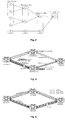
- Fig. 6 shows a conventional configuration of network protection in such a hierarchical network.
- two traffic paths are set up between the edge node A and the edge node C, that is, a working path through the core node D and a protection path through the core node B.
- two traffic flows, #1 and #2 are multiplexed and transmitted over the working path.
- an Operation, Administration and Management (OAM) protocol running on the working path will detect the failure and both traffic flows transmitted over the working path should be switched to the protection path.
- OAM Operation, Administration and Management
- a forwarding key is first extracted from the flow (packet), such as a destination Media Access Control (MAC) address and a Virtual Local Area Network (VLAN) ID for an Ethernet frame, a LSP label for a MPLS packet or an IP destination address for an IP packet. Then, the next hop information can be searched and determined based on the forwarding key.
- packet such as a destination Media Access Control (MAC) address and a Virtual Local Area Network (VLAN) ID for an Ethernet frame, a LSP label for a MPLS packet or an IP destination address for an IP packet.
- MAC Media Access Control
- VLAN Virtual Local Area Network
- the switching node can maintain for each traffic flow the next hop information in both the working path and the protection path as well as an associated status. If a traffic flow needs to be switched to the protection path due to a network failure, the status of the traffic flow can be changed from a normal status to a failure status such that the switching node can select the next hop information for forwarding the traffic flow based on the failure status.
- both approaches may impose heavy workload on the switching node which carries out the protection switching when a large amount of traffic flows are involved, since, in case of a network failure, all the involved traffic flows need to be switched to the protection path and switching node needs to sequentially determine and change the next hop information or the status for each of these traffic flows.
- next hop indexes or next hop information
- traffic flow statuses may exhaust the CPU I/O bandwidth and thus may inversely affect other CPU applications.
- a number of traffic flows may fail to satisfy the switching time requirement (typically 50ms) due to the slow process.
- US 2008/0291910 discloses packet switching methods and packet switches providing a plurality of tunnels on a packet switch by associating each of the plurality of tunnels with a packet switch port and by configuring the packet switch to modify packets relayed by the tunnel to include a transport identifier associated with the tunnel. If the packet switch detects that a first tunnel is no longer operational, the first tunnel is disabled and transmits subsequent packets on another tunnel.
- traffic flows are multiplexed into a (highest level) traffic tunnel and higher level traffic tunnels are multiplexed into a lower level traffic tunnel. If a lower level tunnel is failed, the higher level tunnels multiplexed into the lower level tunnel are failed accordingly. The higher level tunnels cannot recover from the failure if the corresponding lower level tunnel is in a failure status. Additionally, the failure detection mechanisms for different levels may be independent from each other. In response to the detection of a failure status on a tunnel, all the traffic flows multiplexed, directly or indirectly, into the level tunnel can be immediately switched to the protection path.
- the inherent multiplexing hierarchy of the communication network is utilized for path switching. And a traffic flow can be switched from the working path to the protection path if a failure status is detected for any of tunnels of all levels into which it is multiplexed.
- the reliability of the protection switching can be improved and the amount of information required to be changed before the protection switching, and thus the switching latency, can be significantly reduced.
- Fig. 1 is a block diagram of the path switching apparatus 100 according to an embodiment of the present invention.
- the apparatus 100 operates in a network comprising at least a first path (e.g., a working path) and a second path (e.g., a protection path).
- the apparatus 100 can be any node in the network which is capable of protection switching, such as but not limited to an ingress edge router in a MPLS domain.
- the apparatus 100 comprises a failure status determining unit 110 and a forwarding unit 120.
- the apparatus 100 may further comprise other units/components necessary for the operation of the apparatus, whose description is omitted here so as not to obscure the concept of the present invention.
- each of the units 110 and 120 can be implemented in hardware, firmware or software, i.e., by a dedicated circuit component or by an appropriately programmed processor.
- the network in which the apparatus 100 operates can be any known or future communication network.
- at least the working path is organized in hierarchy.
- one or more traffic flows are multiplexed into a tunnel, and one or more higher level tunnels are multiplexed into a lower level tunnel.
- the working path and the protection path can be interchanged with each other.
- the failure status determining unit 110 is configured to determine, for an incoming traffic flow, whether any of tunnels on the first path of all levels into which the incoming traffic flow is multiplexed is of a failure status.
- the forwarding unit 120 is configured to forward the incoming traffic flow via the second path, if the failure status determining unit 110 determines that any one of tunnels on the first path of all levels into which the incoming traffic flow is multiplexed is of the failure status.
- Fig. 3 illustrates an exemplary path switching process of the present invention.
- the multiplexing hierarchy for the working path contains a number of M levels and is represented by "group". That is, in the working path, traffic flows which are multiplexed into the same level M (the highest level) tunnel can be mapped into a "group” (level M group). Also, in the working path, higher level (level i +1) tunnels which are multiplexed into the same immediately lower level (level i ) tunnels can be mapped into a "group” (level i group), where i is an integer satisfying 1 ⁇ i ⁇ M-1.
- a level M group corresponds to a level M tunnel in the working path into which one or more traffic flows are multiplexed
- a level i group corresponds to a level i tunnel in the working path into which one or more level i +1 tunnels are multiplexed.
- an incoming traffic flow carries one or more forwarding keys for switching/routing.
- the forwarding keys can be a destination MAC address and a VLAN ID for an Ethernet frame, a LSP label for a MPLS packet or an IP destination address for an IP packet.
- a next hop determining unit (not shown) of the apparatus 100 extracts a forwarding key from the traffic flow, and determines both a next hop in the first path and a next hop in the second path by referencing a forwarding table based on the extracted forwarding key.
- the forwarding table holds, for each forwarding key, a next hop index for the working path, a next hop index for the protection path and a group index for the highest level (level M).
- the search key for this table i.e., the forwarding key, can be application specific.
- the next hop determining unit is not essential to the present invention. The solution of the present invention does no rely on any specific unit/step for determining the next hops in the first and the second paths for a traffic flow.
- the apparatus 100 may maintain a next hop working table, a next hop protection table, and a number of M group tables each for one of the M levels.
- the next hop working table holds the next hop information for the working path, such as the next hop header information, output ports number, etc.
- the search key for this table is the next hop index for the working path as output from the forwarding table.
- the next hop information for the working path can be retrieved from the next hop working table and the forwarding unit 120 can forward a traffic flow in the working path based on the retrieved next hop information.
- the next hop working table holds the next hop information for the protection path, such as the next hop header information, output ports number, etc.
- the search key for this table is the next hop index for the working path as output from the forwarding table.
- the next hop information for the protection path can be retrieved from the next hop protection table and the forwarding unit 120 can forward a traffic flow in the protection path based on the retrieved next hop information.
- a level i group table holds the grouping relationship as well as a group status for each level i group. That is, each entry of level i group table is associated with a level i group corresponding to a level i traffic tunnel.
- the grouping relationship of a group is identified by its group index. If a level i + 1 group S i +1 has its group index indexed to a level i group S i , then the group S i +1 belongs to the group S i , i.e., S i ⁇ S i + 1 , which means that the corresponding level i+1 traffic tunnel is created on, or multiplexed into, the corresponding level i traffic tunnel.
- a traffic flow will be forwarded via the working path if and only if all the groups to which it belongs are in normal state; otherwise, it will be forwarded via the protection path.
- next hop information for both the working path and the protection path is configured, either manually or by means of signaling. Then it is identified if the next hop information for the traffic flow exists in the next hop working table and the next hop protection table. If the next hop information exists, the next hop index for the traffic flow is indexed to the existing next hop information entry. Otherwise, a new next hop information entry is created in next hop working and protection tables and the next hop index is indexed to the created entry. Then, it is identified if the traffic flow belongs to an existing highest level (level M) group.
- level M lowest level
- the group index in the forwarding table is indexed to the existing level M group entry; otherwise, a new group is created in level M group table and the group index in the forwarding table is indexed to the created level M group.
- the group index for the highest level can be obtained for a traffic flow.
- the level M group index is then used for obtaining the level M group status, i.e., the status of the level M tunnel, as well as the level M-1 group index, by referencing the level M group table.
- the level M-1 group index is in turn used for obtaining the level M-1 group status, i.e., the status of the level M-1 tunnel, as well as the level M-2 group index, by referencing the level M-1 group table, and so on.
- the failure status determining unit 110 can determine the status of each tunnel on the first path of all levels into which the incoming traffic flow is multiplexed.
- the failure status determining unit 110 can be further configured to judge, from the highest level tunnel, whether the tunnel on each of the levels into which the incoming traffic flow is multiplexed is of the failure status.
- determination order from the highest to the lowest level is only an embodiment of the present invention. The present invention is not limited to this determination order.
- the failure status determining unit 110 can determine the statuses of all of the levels concurrently. In this case, for example, by referencing the forwarding table based on the forwarding key, the group index for each of the levels (levels 1 to M) can be obtained for a traffic flow.
- the statuses of all the groups are determined by the failure status determining unit 110, as shown in Fig. 3 .
- the forwarding unit 120 will forward the traffic flow via the second path if the failure status determining unit 110 determines that any of the group statuses is the failure status.
- the forwarding unit 120 will forward the traffic flow via the first path if the failure status determining unit 110 determines that none of the group status is the failure status.
- the forwarding unit 120 can forward the traffic flow via the second path once the failure status determining unit 110 determines any of the group statuses is the failure status. That is, once the failure status determining unit 110 determines that any group status is the failure status, it may stop the determination on the statuses of the remaining groups, which may further reduce the switching time.
- a failure status is set for level n+1 tunnel if a level n tunnel into which the level n+1 tunnel is multiplexed is set as failure status, wherein n is an integer no smaller than 1. In this way, it is possible for the switching node to detect the failure in the working path even more quickly, especially in the case where the failure status determining unit 110 is configured to judge from the highest level tunnel whether the tunnel on each of the levels into which the incoming traffic flow is multiplexed is of the failure status.
- the forwarding unit 120 In order to forward the incoming traffic flow via the second path, the forwarding unit 120 forwards the traffic flow to the next hop in the second path as determined by the next hop determining unit. On the other hand, in order to forward the incoming traffic flow via the first path, the forwarding unit 120 forwards the traffic flow to the next hop in the first path as determined by the next hop determining unit.
- a normal status can be reset for a tunnel when a failure is recovered for the tunnel.
- the failure/recovery of a tunnel can be detected by an OAM protocol running on the corresponding level or by status information reported from the physical layer (for level 1).
- Fig. 4 is a schematic diagram showing an exemplary multiplexing hierarchy, i.e., grouping relationship, for the working path.
- Fig. 4 shows, by way of example, five traffic flows F 1 , F 2 , F 3 , F 4 and F 5 .
- the traffic flows F 1 and F 2 are multiplexed into a level 3 tunnel (group) S 31
- the traffic flows F 3 and F 4 are multiplexed into a level 3 tunnel (group) S 32
- the traffic flows F 5 is multiplexed into a level 3 tunnel (group) S 33 .
- level 3 tunnels (groups) S 31 and S 32 are multiplexed into a level 2 tunnel (group) S 21
- level 3 tunnel (group) S 33 is multiplexed into a level 2 tunnel (group) S 22
- the level 2 tunnels (groups) S 21 and S 22 are multiplexed into a level 1 tunnel (group) S 11 . Therefore, the following grouping relationship can be obtained: F 1 ⁇ S 31 , F 2 ⁇ S 31 , F 3 ⁇ S 32 , F 4 ⁇ S 32 , F 5 ⁇ S 33 ; S 31 ⁇ S 21 , S 32 ⁇ S 21 , S 33 ⁇ S 22 ; and S 21 ⁇ S 11 , F 22 ⁇ S 11 .
- the traffic flows F 1 and F 2 will be indexed to the group S 31
- the traffic flows F 3 and F 4 will be indexed to the level 3 group S 32
- the traffic flows F 5 will be indexed to the level 3 group S 33
- the groups S 31 and S 32 will be indexed to the level 2 group S 21
- the group S 33 will be indexed to the level 2 group S 22
- the group S 21 and S 22 will be indexed to the level 1 group S 11 .
- the traffic flows F 1 , F 2 , F 3 and F 4 will be switched to the protection path.
- the traffic flows F 1 and F 2 will be switched to the protection path.
- all of the traffic flows F 1 to F 5 will be switched to the protection path.
- Fig. 2 is a flowchart illustrating the path switching method 200 according to an embodiment of the present invention.
- the method 200 can be carried out by any node in a network which is capable of protection switching, such as but not limited to an ingress edge router in a MPLS domain.
- an incoming traffic flow is multiplexed into a tunnel (i.e., a highest level tunnel). Further, one or more higher level tunnels are multiplexed into a lower level tunnel, so as to form a multiplexing hierarchy.
- step S210 it is determined for an incoming traffic flow whether any of tunnels on the first path of all levels into which the incoming traffic flow is multiplexed is of a failure status.
- the incoming traffic flow is forwarded via the second path if any of the tunnels on the first path of all levels into which the incoming traffic flow is multiplexed is determined to be of a failure status at step S210.
- the incoming traffic flow is forwarded via the first path if none of the tunnels on the first path of all levels into which the incoming traffic flow is multiplexed is determined to be of a failure status at step S210.
- the determining step S210 may comprise: judging, from the highest level tunnel, whether the tunnel on each of the levels into which the incoming traffic flow is multiplexed is of the failure status.
- a failure status is set for an (n+1) th level tunnel if an n th level tunnel into which the (n+1) th level tunnel is multiplexed is set as failure status, wherein n is an integer no smaller than 1.
- the method 200 may further comprise: extracting a forwarding key from the incoming traffic flow, before the determining step S210.
- the method 200 can further comprise a step of determining both a next hop in the first path and a next hop in the second path based on the extracted forwarding key.
- the traffic flow for forwarding the incoming traffic flow via the second path, the traffic flow is forwarded to the determined next hop in the second path; and for forwarding the incoming traffic flow via the first path, the traffic flow is forwarded to the determined next hop in the first path.
- Fig. 5 is a schematic diagram showing an exemplary scenario of protection switching according to an embodiment of the present invention.
- the edge router A and the edge router C there are two LSPs created between the edge router A and the edge router C, that is, a working path through the provider router D and a protection path through the provider node B.
- a number of PWs are multiplexed into each LSP, with traffic flows multiplexed into each PW.
- the OAM for detecting the failure, i.e., connectivity loss, runs on the LSP level.
- the present invention can be applied to the edge node A.
- the PWs can be regarded as level 3 tunnels (groups)
- the LSPs can be regarded as level 2 tunnels (groups)
- the physical links from the edge node A to provider router D can be regarded as level 1 tunnels (groups).
- the PWs multiplexed into a same LSP #1 (PW#1 to PW#n in the figure) will have their group indexes indexed to that LSP #1
- LSPs multiplexed into the same physical link three LSPs between the router A and the router D in the figure) will have their group indexes indexed to that physical link.
- the level 2 group corresponding to the failed LSP will be set to the failure state.
- a LSP failure for example, a LSP failure between the provider router D and edge router C
- the level 2 group corresponding to the failed LSP will be set to the failure state.
- the traffic flow in response to the determination of the failure status of the level 2 tunnel (LSP), the traffic flow will be forwarded to the protection path, typically by pushing a different LSP label and redirecting the packet to the protection path port.
- the level 1 group corresponding to the failed physical link will be set to the failure state. In this case, all the traffic flows running on the physical link will be switched to the protection path.
Landscapes
- Engineering & Computer Science (AREA)
- Computer Networks & Wireless Communication (AREA)
- Signal Processing (AREA)
- Data Exchanges In Wide-Area Networks (AREA)
Claims (10)
- Pfadwechselverfahren in einem Netzwerk, das mindestens einen ersten Pfad und einen zweiten Pfad umfasst, wobei für den ersten Pfad ein oder mehrere eingehende Verkehrsflüsse in einen Tunnel gemultiplext werden, und ein oder mehrere Tunnel einer höheren Ebene in einen Tunnel einer niedrigeren Ebene gemultiplext werden, wobei das Verfahren umfasst:- Bestimmen (S210) für den eingehenden Verkehrsfluss, dass einer der Tunnel auf dem ersten Pfad aller Ebenen, in welche der eingehende Verkehrsfluss gemultiplext wird, einen Fehlerstatus aufweist, und- Weiterleiten (S220) des eingehenden Verkehrsflusses über den zweiten Pfad; andernfalls- Bestimmen für den eingehenden Verkehrsfluss, dass keiner der Tunnel auf dem ersten Pfad aller Ebenen, in welche der eingehende Verkehrsfluss gemultiplext wird, den Fehlerstatus aufweist, und- Weiterleiten (S230) des eingehenden Verkehrsflusses über den ersten Pfad.
- Pfadwechselverfahren nach Anspruch 1, wobei der Bestimmungsschritt (S210) umfasst:- Beurteilen aus dem Tunnel der höchsten Ebene, ob der Tunnel auf jeder der Ebenen, in welche der eingehende Verkehrsfluss gemultiplext wird, den Fehlerstatus aufweist.
- Pfadwechselverfahren nach Anspruch 1, wobei ein Fehlerstatus für einen Tunnel einer (n + 1)-ten Ebene gesetzt wird, wenn ein Tunnel einer n-ten Ebene, in welchen der Tunnel der (n + 1)-ten Ebene gemultiplext wird, als Fehlerstatus gesetzt ist, wobei n eine ganze Zahl nicht kleiner als 1 ist.
- Pfadwechselverfahren nach Anspruch 1, ferner umfassend:- Extrahieren eines Weiterleitungsschlüssels aus dem eingehenden Verkehrsfluss vor dem Bestimmungsschritt und- Bestimmen sowohl eines nächsten Hops im ersten Pfad als auch eines nächsten Hops im zweiten Pfad basierend auf dem extrahierten Weiterleitungsschlüssel.
- Pfadwechselverfahren nach Anspruch 4, wobei
zum Weiterleiten (S220) des eingehenden Verkehrsflusses über den zweiten Pfad der Verkehrsfluss zum bestimmten nächsten Hop im zweiten Pfad weitergeleitet wird, und
zum Weiterleiten (S230) des eingehenden Verkehrsflusses über den ersten Pfad der Verkehrsfluss zum bestimmten nächsten Hop im ersten Pfad weitergeleitet wird; - Pfadwechselvorrichtung (100) in einem Netzwerk, das mindestens einen ersten Pfad und einen zweiten Pfad umfasst, wobei für den ersten Pfad ein oder mehrere eingehende Verkehrsflüsse in einen Tunnel gemultiplext werden, und ein oder mehrere Tunnel einer höheren Ebene in einen Tunnel einer niedrigeren Ebene gemultiplext werden, wobei die Vorrichtung (100) umfasst:eine Fehlerstatusbestimmungseinheit (110), die so konfiguriert ist, dass sie für den eingehenden Verkehrsfluss bestimmt, ob einer der Tunnel auf dem ersten Pfad aller Ebenen, in welche der eingehende Verkehrsfluss gemultiplext wird, einen Fehlerstatus aufweist, undeine Weiterleitungseinheit (120), die so konfiguriert ist, dass sie den eingehenden Verkehrsfluss über den zweiten Pfad weiterleitet, wenn die Fehlerstatusbestimmungseinheit bestimmt, dass einer der Tunnel auf dem ersten Pfad aller Ebenen, in welche der eingehende Verkehrsfluss gemultiplext wird, den Fehlerstatus aufweist, und die Weiterleitungseinheit (120) ferner so konfiguriert ist, dass sie den eingehenden Verkehrsfluss über den ersten Pfad weiterleitet, wenn die Fehlerstatusbestimmungseinheit (110) bestimmt, dass keiner der Tunnel auf dem ersten Pfad aller Ebenen, in welche der eingehende Verkehrsfluss gemultiplext wird, den Fehlerstatus aufweist.
- Pfadwechselvorrichtung (100) nach Anspruch 6, wobei die Fehlerstatusbestimmungseinheit (110) ferner so konfiguriert ist, dass sie aus dem Tunnel der höchsten Ebene beurteilt, ob der Tunnel auf jeder der Ebenen, in welchen der eingehenden Verkehrsfluss gemultiplext wird, den Fehlerstatus aufweist.
- Pfadwechselvorrichtung (100) nach Anspruch 6, wobei ein Fehlerstatus für einen Tunnel der (n + 1)-ten Ebene gesetzt wird, wenn ein Tunnel einer n-ten Ebene, in welchen der Tunnel der (n + 1)-ten Ebene gemultiplext wird, als Fehlerstatus gesetzt ist, wobei n eine ganze Zahl nicht kleiner als 1 ist.
- Pfadwechselvorrichtung(100) nach Anspruch 6, ferner umfassend:- eine Einheit zum Bestimmen des nächsten Hops, die so konfiguriert ist, dass sie einen Weiterleitungsschlüssel aus dem eingehenden Verkehrsfluss extrahiert und sowohl einen nächsten Hop im ersten Pfad als auch einen nächsten Hop im zweiten Pfad basierend auf dem extrahierten Weiterleitungsschlüssel bestimmt.
- Pfadwechselvorrichtung (100) nach Anspruch 9, wobei
die Weiterleitungseinheit (120) so konfiguriert ist, dass sie zum Weiterleiten des eingehenden Verkehrsflusses über den zweiten Pfad den Verkehrsfluss zum bestimmten nächsten Hop im zweiten Pfad weiterleitet, und
die Weiterleitungseinheit (120) so konfiguriert ist, dass sie zum Weiterleiten des eingehenden Verkehrsflusses über den ersten Pfad der Verkehrsfluss zum bestimmten nächsten Hop im ersten Pfad weiterleitet.
Applications Claiming Priority (1)
| Application Number | Priority Date | Filing Date | Title |
|---|---|---|---|
| PCT/CN2011/001630 WO2013044408A1 (en) | 2011-09-27 | 2011-09-27 | Method and apparatus for path switching |
Publications (3)
| Publication Number | Publication Date |
|---|---|
| EP2748986A1 EP2748986A1 (de) | 2014-07-02 |
| EP2748986A4 EP2748986A4 (de) | 2015-12-30 |
| EP2748986B1 true EP2748986B1 (de) | 2018-12-12 |
Family
ID=47994089
Family Applications (1)
| Application Number | Title | Priority Date | Filing Date |
|---|---|---|---|
| EP11873154.6A Not-in-force EP2748986B1 (de) | 2011-09-27 | 2011-09-27 | Verfahren und vorrichtung für pfadumschaltung |
Country Status (3)
| Country | Link |
|---|---|
| US (1) | US9407496B2 (de) |
| EP (1) | EP2748986B1 (de) |
| WO (1) | WO2013044408A1 (de) |
Families Citing this family (9)
| Publication number | Priority date | Publication date | Assignee | Title |
|---|---|---|---|---|
| US20150207675A1 (en) * | 2012-08-28 | 2015-07-23 | Nec Corporation | Path Control System, Control Apparatus, Edge Node, Path Control Method, And Program |
| US10159079B2 (en) | 2014-05-21 | 2018-12-18 | Arizona Board Of Regents On Behalf Of Arizona State University | Systems and methods for social-aware cooperative device-to-device communications |
| US9497686B2 (en) * | 2014-07-21 | 2016-11-15 | Verizon Patent And Licensing Inc. | Providing out-of-band management traffic and data traffic over a backup path via a dual use device |
| US10404598B1 (en) * | 2017-05-08 | 2019-09-03 | Amazon Technologies, Inc. | Managing next hop groups in routers |
| CN109672617B (zh) * | 2017-10-16 | 2021-07-27 | 深圳市中兴微电子技术有限公司 | 一种mpls层次化保护倒换的方法、装置及存储介质 |
| US10887218B2 (en) * | 2018-06-27 | 2021-01-05 | At&T Intellectual Property I, L.P. | Enhanced dynamic encryption packet segmentation |
| CN111698152B (zh) | 2019-03-15 | 2021-09-14 | 华为技术有限公司 | 一种故障保护方法、节点及存储介质 |
| CN110071843B (zh) * | 2019-05-08 | 2021-11-26 | 浪潮云信息技术股份公司 | 一种基于流路径分析的故障定位方法及装置 |
| CN118075367A (zh) * | 2022-11-24 | 2024-05-24 | 中兴通讯股份有限公司 | 数据流的传输方法、装置、电子设备及存储介质 |
Family Cites Families (15)
| Publication number | Priority date | Publication date | Assignee | Title |
|---|---|---|---|---|
| US7054265B1 (en) * | 1999-06-09 | 2006-05-30 | Hitachi, Ltd. | Communication apparatus and communication system |
| WO2002082720A2 (en) | 2001-04-04 | 2002-10-17 | Roke Manor Research Limited | Automated network with tunnels and method of data routing |
| AU2003281996A1 (en) * | 2003-08-07 | 2005-02-25 | Pirelli & C. S.P.A. | A modular, easily configurable and expandible node structure for an optical communications network |
| CN100550823C (zh) | 2003-12-26 | 2009-10-14 | 上海贝尔阿尔卡特股份有限公司 | 一种具有快速保护和公平特性的以太网传送设备及方法 |
| US8379509B2 (en) * | 2004-04-29 | 2013-02-19 | Alcatel Lucent | Electronic device protection systems and methods |
| CN101051995B (zh) * | 2006-06-05 | 2012-07-04 | 华为技术有限公司 | 基于无连接网络的保护倒换方法 |
| CN101146016B (zh) | 2006-09-15 | 2010-07-07 | 华为技术有限公司 | 以太帧传输方法和以太网架构 |
| US8867338B2 (en) * | 2006-09-19 | 2014-10-21 | Futurewei Technologies, Inc. | Faults Propagation and protection for connection oriented data paths in packet networks |
| CN101193052B (zh) * | 2006-11-22 | 2011-06-01 | 华为技术有限公司 | 在多协议标签交换中实现子网连接保护的方法和系统 |
| US7948874B2 (en) | 2007-05-24 | 2011-05-24 | World Wide Packets, Inc. | Transitioning a virtual interface from one tunnel to another tunnel |
| US8477769B2 (en) * | 2008-05-13 | 2013-07-02 | Verizon Patent And Licensing Inc. | Flexible shared mesh protection services for intelligent TDM-based optical transport networks |
| CN102064995B (zh) * | 2009-11-18 | 2012-12-19 | 中兴通讯股份有限公司 | 一种虚拟专用局域网络中链路保护的方法及设备 |
| CN101827034A (zh) | 2010-05-12 | 2010-09-08 | 中兴通讯股份有限公司 | 实现快速重路由的方法及装置 |
| US9094335B2 (en) * | 2011-02-22 | 2015-07-28 | Cisco Technology, Inc. | Packet switching label assignment across multiple packet switching forwarding groups |
| US9755937B2 (en) * | 2011-05-05 | 2017-09-05 | Infinera Corporation | Supporting OAM on protecting connections in shared mesh protection environment |
-
2011
- 2011-09-27 WO PCT/CN2011/001630 patent/WO2013044408A1/en not_active Ceased
- 2011-09-27 EP EP11873154.6A patent/EP2748986B1/de not_active Not-in-force
- 2011-09-27 US US14/344,588 patent/US9407496B2/en not_active Expired - Fee Related
Non-Patent Citations (1)
| Title |
|---|
| None * |
Also Published As
| Publication number | Publication date |
|---|---|
| EP2748986A1 (de) | 2014-07-02 |
| EP2748986A4 (de) | 2015-12-30 |
| US9407496B2 (en) | 2016-08-02 |
| US20140328166A1 (en) | 2014-11-06 |
| WO2013044408A1 (en) | 2013-04-04 |
Similar Documents
| Publication | Publication Date | Title |
|---|---|---|
| EP2748986B1 (de) | Verfahren und vorrichtung für pfadumschaltung | |
| US7801049B2 (en) | Method, system and node for implementing subnetwork connection protection in multi-protocol label switching network | |
| US7859995B2 (en) | Protected-far-node-based solution for fault-resilient MPLS/T-MPLS multicast services | |
| US7602702B1 (en) | Fast reroute of traffic associated with a point to multi-point network tunnel | |
| CN105024985B (zh) | 一种报文处理方法及装置 | |
| EP2992643B1 (de) | Verfahren für den betrieb eines netzwerkknotens für lastausgleich | |
| EP2709314B1 (de) | Vermeidung von Verkehrsverlust in einem Multihome-Ethernetring, in einem aktiven Standbymodus, zu einem virtuellen privaten LAN-Diensttransportnetzwerk | |
| CN111064596B (zh) | 对于用于多宿主节点故障的bum流量的节点保护 | |
| US20150334006A1 (en) | Method to do fast traffic switchover based on server layer status | |
| RU2612599C1 (ru) | Устройство управления, система связи, способ управления коммутаторами и программа | |
| US9838310B1 (en) | Mechanism for optimized customer MAC address flushing in PBB-EVPN | |
| US20160378606A1 (en) | Fast convergence for failures of large scale virtual ethernet segments in evpn and pbb-evpn | |
| WO2015095996A1 (en) | Technique for network service availability | |
| CN111698152A (zh) | 一种故障保护方法、节点及存储介质 | |
| CN103843293A (zh) | 通信系统、传输装置、通信装置、故障通知方法以及存储程序的非瞬时计算机可读介质 | |
| CN101159690A (zh) | 多协议标签交换转发方法、装置及标签交换路径管理模块 | |
| EP3783837A1 (de) | Verfahren und vorrichtung zur dienstfehlerortung | |
| JP4297636B2 (ja) | 伝送システム | |
| US12388745B2 (en) | Method and apparatus for performing protection switching in segment routing SR network | |
| CN102771087B (zh) | 快速标记交换路径告警机制 | |
| Thorat et al. | Enhanced local detouring mechanisms for rapid and lightweight failure recovery in OpenFlow networks | |
| US20170195203A1 (en) | Method, apparatus, and system for implementing packet loss detection | |
| US11595119B2 (en) | Protection switching based on exchange of protection information | |
| KR20130079596A (ko) | 네트워크 구성 방법, 링 네트워크 시스템, 노드 | |
| EP2640016B1 (de) | Tunnel-multiplexverfahren für eine lineare schutzgruppe und endknoten eines tunnels |
Legal Events
| Date | Code | Title | Description |
|---|---|---|---|
| PUAI | Public reference made under article 153(3) epc to a published international application that has entered the european phase |
Free format text: ORIGINAL CODE: 0009012 |
|
| 17P | Request for examination filed |
Effective date: 20140319 |
|
| AK | Designated contracting states |
Kind code of ref document: A1 Designated state(s): AL AT BE BG CH CY CZ DE DK EE ES FI FR GB GR HR HU IE IS IT LI LT LU LV MC MK MT NL NO PL PT RO RS SE SI SK SM TR |
|
| DAX | Request for extension of the european patent (deleted) | ||
| RA4 | Supplementary search report drawn up and despatched (corrected) |
Effective date: 20151127 |
|
| RIC1 | Information provided on ipc code assigned before grant |
Ipc: H04L 12/703 20130101ALI20151123BHEP Ipc: H04L 12/24 20060101ALI20151123BHEP Ipc: H04L 12/707 20130101AFI20151123BHEP |
|
| STAA | Information on the status of an ep patent application or granted ep patent |
Free format text: STATUS: EXAMINATION IS IN PROGRESS |
|
| 17Q | First examination report despatched |
Effective date: 20170103 |
|
| REG | Reference to a national code |
Ref country code: DE Ref legal event code: R079 Ref document number: 602011054863 Country of ref document: DE Free format text: PREVIOUS MAIN CLASS: H04L0012700000 Ipc: H04L0012707000 |
|
| GRAP | Despatch of communication of intention to grant a patent |
Free format text: ORIGINAL CODE: EPIDOSNIGR1 |
|
| STAA | Information on the status of an ep patent application or granted ep patent |
Free format text: STATUS: GRANT OF PATENT IS INTENDED |
|
| RIC1 | Information provided on ipc code assigned before grant |
Ipc: H04L 12/707 20130101AFI20180809BHEP Ipc: H04L 12/703 20130101ALI20180809BHEP |
|
| INTG | Intention to grant announced |
Effective date: 20180903 |
|
| GRAS | Grant fee paid |
Free format text: ORIGINAL CODE: EPIDOSNIGR3 |
|
| GRAA | (expected) grant |
Free format text: ORIGINAL CODE: 0009210 |
|
| STAA | Information on the status of an ep patent application or granted ep patent |
Free format text: STATUS: THE PATENT HAS BEEN GRANTED |
|
| AK | Designated contracting states |
Kind code of ref document: B1 Designated state(s): AL AT BE BG CH CY CZ DE DK EE ES FI FR GB GR HR HU IE IS IT LI LT LU LV MC MK MT NL NO PL PT RO RS SE SI SK SM TR |
|
| REG | Reference to a national code |
Ref country code: GB Ref legal event code: FG4D |
|
| REG | Reference to a national code |
Ref country code: CH Ref legal event code: EP |
|
| REG | Reference to a national code |
Ref country code: AT Ref legal event code: REF Ref document number: 1077457 Country of ref document: AT Kind code of ref document: T Effective date: 20181215 |
|
| REG | Reference to a national code |
Ref country code: DE Ref legal event code: R096 Ref document number: 602011054863 Country of ref document: DE |
|
| REG | Reference to a national code |
Ref country code: IE Ref legal event code: FG4D |
|
| REG | Reference to a national code |
Ref country code: NL Ref legal event code: MP Effective date: 20181212 |
|
| REG | Reference to a national code |
Ref country code: LT Ref legal event code: MG4D |
|
| PG25 | Lapsed in a contracting state [announced via postgrant information from national office to epo] |
Ref country code: ES Free format text: LAPSE BECAUSE OF FAILURE TO SUBMIT A TRANSLATION OF THE DESCRIPTION OR TO PAY THE FEE WITHIN THE PRESCRIBED TIME-LIMIT Effective date: 20181212 Ref country code: BG Free format text: LAPSE BECAUSE OF FAILURE TO SUBMIT A TRANSLATION OF THE DESCRIPTION OR TO PAY THE FEE WITHIN THE PRESCRIBED TIME-LIMIT Effective date: 20190312 Ref country code: HR Free format text: LAPSE BECAUSE OF FAILURE TO SUBMIT A TRANSLATION OF THE DESCRIPTION OR TO PAY THE FEE WITHIN THE PRESCRIBED TIME-LIMIT Effective date: 20181212 Ref country code: LT Free format text: LAPSE BECAUSE OF FAILURE TO SUBMIT A TRANSLATION OF THE DESCRIPTION OR TO PAY THE FEE WITHIN THE PRESCRIBED TIME-LIMIT Effective date: 20181212 Ref country code: NO Free format text: LAPSE BECAUSE OF FAILURE TO SUBMIT A TRANSLATION OF THE DESCRIPTION OR TO PAY THE FEE WITHIN THE PRESCRIBED TIME-LIMIT Effective date: 20190312 Ref country code: LV Free format text: LAPSE BECAUSE OF FAILURE TO SUBMIT A TRANSLATION OF THE DESCRIPTION OR TO PAY THE FEE WITHIN THE PRESCRIBED TIME-LIMIT Effective date: 20181212 Ref country code: FI Free format text: LAPSE BECAUSE OF FAILURE TO SUBMIT A TRANSLATION OF THE DESCRIPTION OR TO PAY THE FEE WITHIN THE PRESCRIBED TIME-LIMIT Effective date: 20181212 |
|
| REG | Reference to a national code |
Ref country code: AT Ref legal event code: MK05 Ref document number: 1077457 Country of ref document: AT Kind code of ref document: T Effective date: 20181212 |
|
| PG25 | Lapsed in a contracting state [announced via postgrant information from national office to epo] |
Ref country code: SE Free format text: LAPSE BECAUSE OF FAILURE TO SUBMIT A TRANSLATION OF THE DESCRIPTION OR TO PAY THE FEE WITHIN THE PRESCRIBED TIME-LIMIT Effective date: 20181212 Ref country code: AL Free format text: LAPSE BECAUSE OF FAILURE TO SUBMIT A TRANSLATION OF THE DESCRIPTION OR TO PAY THE FEE WITHIN THE PRESCRIBED TIME-LIMIT Effective date: 20181212 Ref country code: RS Free format text: LAPSE BECAUSE OF FAILURE TO SUBMIT A TRANSLATION OF THE DESCRIPTION OR TO PAY THE FEE WITHIN THE PRESCRIBED TIME-LIMIT Effective date: 20181212 Ref country code: GR Free format text: LAPSE BECAUSE OF FAILURE TO SUBMIT A TRANSLATION OF THE DESCRIPTION OR TO PAY THE FEE WITHIN THE PRESCRIBED TIME-LIMIT Effective date: 20190313 |
|
| PG25 | Lapsed in a contracting state [announced via postgrant information from national office to epo] |
Ref country code: NL Free format text: LAPSE BECAUSE OF FAILURE TO SUBMIT A TRANSLATION OF THE DESCRIPTION OR TO PAY THE FEE WITHIN THE PRESCRIBED TIME-LIMIT Effective date: 20181212 |
|
| PG25 | Lapsed in a contracting state [announced via postgrant information from national office to epo] |
Ref country code: CZ Free format text: LAPSE BECAUSE OF FAILURE TO SUBMIT A TRANSLATION OF THE DESCRIPTION OR TO PAY THE FEE WITHIN THE PRESCRIBED TIME-LIMIT Effective date: 20181212 Ref country code: PT Free format text: LAPSE BECAUSE OF FAILURE TO SUBMIT A TRANSLATION OF THE DESCRIPTION OR TO PAY THE FEE WITHIN THE PRESCRIBED TIME-LIMIT Effective date: 20190412 Ref country code: IT Free format text: LAPSE BECAUSE OF FAILURE TO SUBMIT A TRANSLATION OF THE DESCRIPTION OR TO PAY THE FEE WITHIN THE PRESCRIBED TIME-LIMIT Effective date: 20181212 Ref country code: PL Free format text: LAPSE BECAUSE OF FAILURE TO SUBMIT A TRANSLATION OF THE DESCRIPTION OR TO PAY THE FEE WITHIN THE PRESCRIBED TIME-LIMIT Effective date: 20181212 |
|
| PG25 | Lapsed in a contracting state [announced via postgrant information from national office to epo] |
Ref country code: EE Free format text: LAPSE BECAUSE OF FAILURE TO SUBMIT A TRANSLATION OF THE DESCRIPTION OR TO PAY THE FEE WITHIN THE PRESCRIBED TIME-LIMIT Effective date: 20181212 Ref country code: IS Free format text: LAPSE BECAUSE OF FAILURE TO SUBMIT A TRANSLATION OF THE DESCRIPTION OR TO PAY THE FEE WITHIN THE PRESCRIBED TIME-LIMIT Effective date: 20190412 Ref country code: SK Free format text: LAPSE BECAUSE OF FAILURE TO SUBMIT A TRANSLATION OF THE DESCRIPTION OR TO PAY THE FEE WITHIN THE PRESCRIBED TIME-LIMIT Effective date: 20181212 Ref country code: RO Free format text: LAPSE BECAUSE OF FAILURE TO SUBMIT A TRANSLATION OF THE DESCRIPTION OR TO PAY THE FEE WITHIN THE PRESCRIBED TIME-LIMIT Effective date: 20181212 Ref country code: SM Free format text: LAPSE BECAUSE OF FAILURE TO SUBMIT A TRANSLATION OF THE DESCRIPTION OR TO PAY THE FEE WITHIN THE PRESCRIBED TIME-LIMIT Effective date: 20181212 |
|
| REG | Reference to a national code |
Ref country code: DE Ref legal event code: R097 Ref document number: 602011054863 Country of ref document: DE |
|
| PLBE | No opposition filed within time limit |
Free format text: ORIGINAL CODE: 0009261 |
|
| STAA | Information on the status of an ep patent application or granted ep patent |
Free format text: STATUS: NO OPPOSITION FILED WITHIN TIME LIMIT |
|
| PG25 | Lapsed in a contracting state [announced via postgrant information from national office to epo] |
Ref country code: AT Free format text: LAPSE BECAUSE OF FAILURE TO SUBMIT A TRANSLATION OF THE DESCRIPTION OR TO PAY THE FEE WITHIN THE PRESCRIBED TIME-LIMIT Effective date: 20181212 Ref country code: SI Free format text: LAPSE BECAUSE OF FAILURE TO SUBMIT A TRANSLATION OF THE DESCRIPTION OR TO PAY THE FEE WITHIN THE PRESCRIBED TIME-LIMIT Effective date: 20181212 Ref country code: DK Free format text: LAPSE BECAUSE OF FAILURE TO SUBMIT A TRANSLATION OF THE DESCRIPTION OR TO PAY THE FEE WITHIN THE PRESCRIBED TIME-LIMIT Effective date: 20181212 |
|
| 26N | No opposition filed |
Effective date: 20190913 |
|
| PG25 | Lapsed in a contracting state [announced via postgrant information from national office to epo] |
Ref country code: TR Free format text: LAPSE BECAUSE OF FAILURE TO SUBMIT A TRANSLATION OF THE DESCRIPTION OR TO PAY THE FEE WITHIN THE PRESCRIBED TIME-LIMIT Effective date: 20181212 |
|
| PG25 | Lapsed in a contracting state [announced via postgrant information from national office to epo] |
Ref country code: MC Free format text: LAPSE BECAUSE OF FAILURE TO SUBMIT A TRANSLATION OF THE DESCRIPTION OR TO PAY THE FEE WITHIN THE PRESCRIBED TIME-LIMIT Effective date: 20181212 |
|
| REG | Reference to a national code |
Ref country code: CH Ref legal event code: PL |
|
| PG25 | Lapsed in a contracting state [announced via postgrant information from national office to epo] |
Ref country code: CH Free format text: LAPSE BECAUSE OF NON-PAYMENT OF DUE FEES Effective date: 20190930 Ref country code: LI Free format text: LAPSE BECAUSE OF NON-PAYMENT OF DUE FEES Effective date: 20190930 Ref country code: LU Free format text: LAPSE BECAUSE OF NON-PAYMENT OF DUE FEES Effective date: 20190927 Ref country code: IE Free format text: LAPSE BECAUSE OF NON-PAYMENT OF DUE FEES Effective date: 20190927 |
|
| REG | Reference to a national code |
Ref country code: BE Ref legal event code: MM Effective date: 20190930 |
|
| PG25 | Lapsed in a contracting state [announced via postgrant information from national office to epo] |
Ref country code: BE Free format text: LAPSE BECAUSE OF NON-PAYMENT OF DUE FEES Effective date: 20190930 |
|
| PG25 | Lapsed in a contracting state [announced via postgrant information from national office to epo] |
Ref country code: CY Free format text: LAPSE BECAUSE OF FAILURE TO SUBMIT A TRANSLATION OF THE DESCRIPTION OR TO PAY THE FEE WITHIN THE PRESCRIBED TIME-LIMIT Effective date: 20181212 |
|
| PG25 | Lapsed in a contracting state [announced via postgrant information from national office to epo] |
Ref country code: HU Free format text: LAPSE BECAUSE OF FAILURE TO SUBMIT A TRANSLATION OF THE DESCRIPTION OR TO PAY THE FEE WITHIN THE PRESCRIBED TIME-LIMIT; INVALID AB INITIO Effective date: 20110927 Ref country code: MT Free format text: LAPSE BECAUSE OF FAILURE TO SUBMIT A TRANSLATION OF THE DESCRIPTION OR TO PAY THE FEE WITHIN THE PRESCRIBED TIME-LIMIT Effective date: 20181212 |
|
| PGFP | Annual fee paid to national office [announced via postgrant information from national office to epo] |
Ref country code: FR Payment date: 20210928 Year of fee payment: 11 |
|
| REG | Reference to a national code |
Ref country code: DE Ref legal event code: R079 Ref document number: 602011054863 Country of ref document: DE Free format text: PREVIOUS MAIN CLASS: H04L0012707000 Ipc: H04L0045240000 |
|
| PGFP | Annual fee paid to national office [announced via postgrant information from national office to epo] |
Ref country code: GB Payment date: 20210927 Year of fee payment: 11 |
|
| PG25 | Lapsed in a contracting state [announced via postgrant information from national office to epo] |
Ref country code: MK Free format text: LAPSE BECAUSE OF FAILURE TO SUBMIT A TRANSLATION OF THE DESCRIPTION OR TO PAY THE FEE WITHIN THE PRESCRIBED TIME-LIMIT Effective date: 20181212 |
|
| PGFP | Annual fee paid to national office [announced via postgrant information from national office to epo] |
Ref country code: DE Payment date: 20220629 Year of fee payment: 12 |
|
| GBPC | Gb: european patent ceased through non-payment of renewal fee |
Effective date: 20220927 |
|
| PG25 | Lapsed in a contracting state [announced via postgrant information from national office to epo] |
Ref country code: FR Free format text: LAPSE BECAUSE OF NON-PAYMENT OF DUE FEES Effective date: 20220930 |
|
| PG25 | Lapsed in a contracting state [announced via postgrant information from national office to epo] |
Ref country code: GB Free format text: LAPSE BECAUSE OF NON-PAYMENT OF DUE FEES Effective date: 20220927 |
|
| REG | Reference to a national code |
Ref country code: DE Ref legal event code: R119 Ref document number: 602011054863 Country of ref document: DE |
|
| PG25 | Lapsed in a contracting state [announced via postgrant information from national office to epo] |
Ref country code: DE Free format text: LAPSE BECAUSE OF NON-PAYMENT OF DUE FEES Effective date: 20240403 |