EP2748992B1 - Procédé de gestion des demandes d'adresse matérielle de réseau comprenant un contrôleur - Google Patents
Procédé de gestion des demandes d'adresse matérielle de réseau comprenant un contrôleur Download PDFInfo
- Publication number
- EP2748992B1 EP2748992B1 EP12778869.3A EP12778869A EP2748992B1 EP 2748992 B1 EP2748992 B1 EP 2748992B1 EP 12778869 A EP12778869 A EP 12778869A EP 2748992 B1 EP2748992 B1 EP 2748992B1
- Authority
- EP
- European Patent Office
- Prior art keywords
- network
- controller
- packet
- end host
- switches
- Prior art date
- Legal status (The legal status is an assumption and is not a legal conclusion. Google has not performed a legal analysis and makes no representation as to the accuracy of the status listed.)
- Not-in-force
Links
- 238000000034 method Methods 0.000 title claims description 34
- 238000012545 processing Methods 0.000 claims description 28
- 230000004044 response Effects 0.000 claims description 16
- 230000000875 corresponding effect Effects 0.000 description 20
- 230000009471 action Effects 0.000 description 18
- 230000008569 process Effects 0.000 description 17
- 238000010586 diagram Methods 0.000 description 11
- 238000004891 communication Methods 0.000 description 6
- 238000012544 monitoring process Methods 0.000 description 2
- 230000002730 additional effect Effects 0.000 description 1
- 230000005540 biological transmission Effects 0.000 description 1
- 230000001276 controlling effect Effects 0.000 description 1
- 230000000694 effects Effects 0.000 description 1
- 230000006870 function Effects 0.000 description 1
- 238000012986 modification Methods 0.000 description 1
- 230000004048 modification Effects 0.000 description 1
- 230000006855 networking Effects 0.000 description 1
- 238000005192 partition Methods 0.000 description 1
- 239000000523 sample Substances 0.000 description 1
Images





Classifications
-
- H—ELECTRICITY
- H04—ELECTRIC COMMUNICATION TECHNIQUE
- H04L—TRANSMISSION OF DIGITAL INFORMATION, e.g. TELEGRAPHIC COMMUNICATION
- H04L41/00—Arrangements for maintenance, administration or management of data switching networks, e.g. of packet switching networks
- H04L41/12—Discovery or management of network topologies
-
- H—ELECTRICITY
- H04—ELECTRIC COMMUNICATION TECHNIQUE
- H04L—TRANSMISSION OF DIGITAL INFORMATION, e.g. TELEGRAPHIC COMMUNICATION
- H04L41/00—Arrangements for maintenance, administration or management of data switching networks, e.g. of packet switching networks
- H04L41/34—Signalling channels for network management communication
- H04L41/342—Signalling channels for network management communication between virtual entities, e.g. orchestrators, SDN or NFV entities
-
- H—ELECTRICITY
- H04—ELECTRIC COMMUNICATION TECHNIQUE
- H04L—TRANSMISSION OF DIGITAL INFORMATION, e.g. TELEGRAPHIC COMMUNICATION
- H04L45/00—Routing or path finding of packets in data switching networks
- H04L45/42—Centralised routing
-
- H—ELECTRICITY
- H04—ELECTRIC COMMUNICATION TECHNIQUE
- H04L—TRANSMISSION OF DIGITAL INFORMATION, e.g. TELEGRAPHIC COMMUNICATION
- H04L45/00—Routing or path finding of packets in data switching networks
- H04L45/66—Layer 2 routing, e.g. in Ethernet based MAN's
-
- H—ELECTRICITY
- H04—ELECTRIC COMMUNICATION TECHNIQUE
- H04L—TRANSMISSION OF DIGITAL INFORMATION, e.g. TELEGRAPHIC COMMUNICATION
- H04L49/00—Packet switching elements
- H04L49/30—Peripheral units, e.g. input or output ports
- H04L49/3009—Header conversion, routing tables or routing tags
-
- H—ELECTRICITY
- H04—ELECTRIC COMMUNICATION TECHNIQUE
- H04L—TRANSMISSION OF DIGITAL INFORMATION, e.g. TELEGRAPHIC COMMUNICATION
- H04L61/00—Network arrangements, protocols or services for addressing or naming
- H04L61/09—Mapping addresses
- H04L61/10—Mapping addresses of different types
- H04L61/103—Mapping addresses of different types across network layers, e.g. resolution of network layer into physical layer addresses or address resolution protocol [ARP]
-
- Y—GENERAL TAGGING OF NEW TECHNOLOGICAL DEVELOPMENTS; GENERAL TAGGING OF CROSS-SECTIONAL TECHNOLOGIES SPANNING OVER SEVERAL SECTIONS OF THE IPC; TECHNICAL SUBJECTS COVERED BY FORMER USPC CROSS-REFERENCE ART COLLECTIONS [XRACs] AND DIGESTS
- Y02—TECHNOLOGIES OR APPLICATIONS FOR MITIGATION OR ADAPTATION AGAINST CLIMATE CHANGE
- Y02D—CLIMATE CHANGE MITIGATION TECHNOLOGIES IN INFORMATION AND COMMUNICATION TECHNOLOGIES [ICT], I.E. INFORMATION AND COMMUNICATION TECHNOLOGIES AIMING AT THE REDUCTION OF THEIR OWN ENERGY USE
- Y02D30/00—Reducing energy consumption in communication networks
Definitions
- This relates to communication networks, and more particularly, to using a controller to manage hardware address discovery in network.
- Packet-based networks such as the internet and local data networks that are connected to the internet include network switches.
- Network switches are used in forwarding packets from packet sources to packet destinations.
- the packets may be sometimes referred to as frames.
- Cross-platform controller clients can be included on the switches in a network.
- the controller clients are able to communicate with a corresponding controller server over network paths. Because the controller clients can be implemented on a variety of switch hardware, it is possible for a single controller to control switch equipment that might otherwise be incompatible.
- End hosts that are coupled to network switches have network addresses and hardware addresses.
- a first end host communicates with a second end host by sending network packets with header fields that identify a network address and a hardware address of the second end host.
- the end hosts have access to the network addresses of other end hosts but not to their hardware addresses.
- the first end host can flood the network with an address resolution protocol (ARP) request that identifies the second end host by its network address and requests that the second end host reply with its hardware address.
- ARP address resolution protocol
- Flooding of a network to send ARP requests can undesirably load the network with unnecessary network traffic because the ARP requests can be sent to many end hosts that ignore the requests (e.g., because those end hosts are not associated with the network address identified in the ARP requests).
- the forwarding of unnecessary ARP requests can impact performance of the network. It would therefore be desirable to be able to provide improved arrangements for performing address discovery of end hosts in a network.
- Other examples of prior art methods can be found disclosed in, for example, US2008/008148A1 , US2008/189769A1 and EP1780943A .
- GUILLERMO IBANEZ ET AL "Implementation of ARP-path low latency bridges in Linux and OpenFlow/NetFPGA", HIGH PERFORMANCE SWITCHING AND ROUTING (HPSR), 2011 IEEE 12TH INTERNATIONAL CONFERENCE ON, IEEE, 4 July 2011 (2011-07-04), pages 30-35, XP032019389, DOI: 10.1109/HPSR.2011.5986000 ISBN:978-1-4244-8454-6 discloses implementation of ARP-path low latency bridges in Linux and OpenFlow/NetFPGA.
- the appended claims are characterised over this document.
- a network may include client switches that are controlled by a controller and non-client switches that are not controlled by the controller.
- the client switches may be organized into groups that are separated by at least one of the non-client switches.
- the controller may fulfill hardware address requests that are received by client switches in the network.
- the hardware address requests may be sent from source end hosts that are coupled to the switches.
- a hardware address request that is sent from a source end host may request the hardware address (e.g., a Media Access Control address, Ethernet address, or other hardware address) of a destination end host.
- a network packet received at a client switch may be forwarded to the controller by the client switch.
- the controller server may retrieve packet information from packet header fields of the packet to determine whether or not the network packet is an ARP request packet.
- the controller may use network topology information to determine how to process the hardware address request.
- the controller may retrieve a requested hardware address from a database of end host addresses.
- the database may be updated with address information retrieved from network packets that flow through the network.
- the controller If the controller is unable to retrieve the requested hardware address, the controller directs the switches to forward the network packet from switch ports on an edge of the network, which is the invention as defined in independent claim 1.
- Networks such as the internet and the local and regional networks that are coupled to the internet rely on packet-based switches. These switches, which are sometimes referred to herein as network switches, packet processing systems, or packet forwarding systems can forward packets based on address information. In this way, data packets that are transmitted by a packet source may be delivered to a packet destination.
- packet sources and destinations are sometimes referred to as end hosts. Examples of end hosts are personal computers, servers, and other computing equipment.
- Network switches range in capability from relatively small Ethernet switches and wireless access points to large rack-based systems that include multiple line cards, redundant power supplies, and supervisor capabilities. It is not uncommon for networks to include equipment from multiple vendors. Network switches from different vendors can be interconnected to form a packet forwarding network, but can be difficult to manage in a centralized fashion due to incompatibilities between their operating systems and control protocols.
- a centralized cross-platform controller server may interact with each of the control clients over respective network links.
- the use of a cross-platform controller server and corresponding controller clients allows potentially disparate network switch equipment to be centrally managed.
- controller server 18 may be implemented on a stand-alone computer, on a cluster of computers, on a set of computers that are distributed among multiple locations, on hardware that is embedded within a network switch, or on other suitable computing equipment 12.
- Controller server 18 can run as a single process on a single computer or can be distributed over several hosts for redundancy. The use of a distributed arrangement may help provide network 10 with resiliency against unexpected network partitions (e.g., a situation in which a network link between two campuses is disrupted).
- controller nodes can exchange information using an intra-controller protocol. For example, if a new end host connects to network hardware (e.g., a switch) that is only connected to a first controller node, that first controller node may use the intra-controller protocol to inform other controller nodes of the presence of the new end host. If desired, a switch or other network component may be connected to multiple controller nodes. Arrangements in which a single controller server is used to control a network of associated switches are sometimes described herein as an example.
- Controller server 18 of FIG. 1 may gather information about the topology of network 10. For example, controller server 18 may send Link Layer Discovery Protocol (LLDP) probe packets throughout the network to discover network connections between client switches. As another example, controller server 18 may instruct client switches to send switch capabilities information to controller server 18 and/or monitor network traffic to maintain a database of end hosts that are coupled to switches in the network. Controller server 18 may use network topology information and information relating to the capabilities of network equipment to determine appropriate paths for packets flowing through the network. Once appropriate paths have been identified, controller server 18 may send corresponding settings data to the hardware in network 10 to ensure that packets flow through correct paths. Network configuration operations such as these may be performed during system setup operations, continuously in the background, or in response to the appearance of new data packets (e.g., packets for which a preexisting path has not been established).
- LLDP Link Layer Discovery Protocol
- Controller server 18 may be used to implement network configuration rules 20.
- Rules 20 may specify which services are available to various network entities.
- rules 20 may specify which users (or type of users) in network 10 may access a particular server.
- Rules 20 may, for example, be maintained in a database at computing equipment 12.
- Controller server 18 and controller clients 30 at respective network switches 14 may use network protocol stacks to communicate over network links 16.
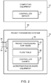
- Each switch (packet forwarding system) 14 may have input-output ports 34. Cables may be used to connect pieces of equipment to ports 34. For example, end hosts such as personal computers, web servers, and other computing equipment may be plugged into ports 34. Ports 34 may also be used to connect one of switches 14 to other switches 14.
- Packet processing circuitry 32 may be used in forwarding packets from one of ports 34 to another of ports 34 and may be used in performing other suitable actions on incoming packets. Packet processing circuit 32 may be implemented using one or more integrated circuits such as dedicated high-speed switch circuits and may serve as a hardware data path. If desired, packet processing software 26 that is running on control unit 24 may be used in implementing a software data path.
- Control unit 24 may include processing and memory circuits (e.g., one or more microprocessors, memory chips, and other control circuitry) for storing and running control software.
- control unit 24 may store and run software such as packet processing software 26, may store flow table 28, and may be used to support the operation of controller clients 30.
- Controller clients 30 and controller server 18 may be compliant with a network switch protocol such as the OpenFlow protocol (see, e.g., OpenFlow Switch Specification version 1.0.0). One or more clients among controller clients 30 may also be compliant with other protocols (e.g., the Simple Network Management Protocol). Using the OpenFlow protocol or other suitable protocols, controller server 18 may provide controller clients 30 with data that determines how switch 14 is to process incoming packets from input-output ports 34.
- a network switch protocol such as the OpenFlow protocol (see, e.g., OpenFlow Switch Specification version 1.0.0).
- One or more clients among controller clients 30 may also be compliant with other protocols (e.g., the Simple Network Management Protocol).
- controller server 18 may provide controller clients 30 with data that determines how switch 14 is to process incoming packets from input-output ports 34.
- flow table data from controller server 18 may be stored in a flow table such as flow table 28.
- the entries of flow table 28 may be used in configuring switch 14 (e.g., the functions of packet processing circuitry 32 and/or packet processing software 26).
- flow table 28 serves as cache storage for flow table entries and a corresponding version of these flow table entries is embedded within the settings maintained by the circuitry of packet processing circuitry 32.
- Flow table 28 may serve as the exclusive storage for flow table entries in switch 14 or may be omitted in favor of flow table storage resources within packet processing circuitry 32.
- flow table entries may be stored using any suitable data structures (e.g., one or more tables, lists, etc.).
- the data of flow table 28 (whether maintained in a database in control unit 24 or embedded within the configuration of packet processing circuitry 32) is referred to herein as forming flow table entries (e.g., rows in flow table 28).
- flow tables 28 storing data that determines how switch 14 is to process incoming packets are merely illustrative. Any packet forwarding decision engine may be used to assist packet forwarding system 14 to make decisions about how to forward network packets. For example, packet forwarding decision engines 28 may direct packet forwarding system 14 to forward network packets to predetermined ports based on attributes of the network packets (e.g., based on network protocol headers).
- switch 14 may be implemented using a general purpose processing platform that runs control software and that omits packet processing circuitry 32 of FIG. 2 .
- controller server 18 on computing equipment 12 may communicate with controller clients 30 on switch (packet forwarding system) 14 over network link 16.
- Controller server 18 may, for example, convey flow table entries to controller clients 30 that are maintained in flow table 28.
- Packet processing software 40 may use network interface 38 to forward and otherwise process packets (e.g., packets transmitted and received using ports 34).
- Network interface 38 may be implemented using one or more network interface cards that are plugged into a system board in switch 14 (as an example).
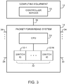
- Network switches such as network switch 14 of FIG. 1 may be implemented using control circuitry that is coupled to one or more high-speed switching integrated circuits ("switch ICs"). This type of configuration is shown in FIG. 3 .
- controller server 18 on computing equipment 12 may communicate with network switch 14 via path 16.
- Switch 14 may include processing circuitry 24 and one or more associated switch ICs 32 such as switch IC 32-1 ... switch IC 32-N.
- Control circuitry 24 may be, for example, based on a microprocessor and memory.
- Switch ICs 32-1...32-N may be dedicated switching circuits that are capable of handling packet processing tasks at high speeds.
- control circuitry 24 may be based on a 500 MHz microprocessor and switch ICs 32-1...32-N may be capable of handling data from 48 of input-output ports 34, each of which has an associated data rate of 1-10 Gbps (as an example).
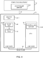
- switch (packet forwarding system) 14 may include a master processor such as processor 24-1 and one or more associated slave processors such as slave processor 24-2.
- Switch ICs 32 and slave processors such as processor 24-2 may be implemented on line cards such as line card 48.
- One or more line cards such as line card 50 may contain processing circuitry (e.g., a microprocessor and memory). Line cards 48 and 50 may be interconnected using backplane 52.
- the controller server may be implemented using the processing resources of a line card.
- the controller server may be implemented on line card 50 as illustrated by controller server 18-B of FIG. 4 .
- the controller server may be implemented on computing equipment 12 (e.g., as controller server 18-A of FIG. 4 ).
- Controller server 18-A or controller server 18-B may communicate with controller clients 30 that are implemented using processors such as processor 24-1 and/or 24-2. Communications between controller server 18-A and the controller clients may take place over network connection 16. Communications between controller server 18-B and the controller clients may take place over backplane 52 (e.g., over a network connection using a protocol such as TCP/IP).
- controller server 18 and controller client 30 may communicate over network path 66 using network protocol stacks such as network protocol stack 58 and network protocol stack 60.
- Stacks 58 and 60 may be, for example Linux TCP/IP stacks or the TCP/IP stack in the VxWorks operating system (as examples).
- Path 66 may be, for example, a path that supports a network connection between switch 14 and external equipment (e.g., network path 16 of FIG. 1 ) or may be a path that supports a network connection in backplane 52 in switch 14, as shown in FIG. 4 . Arrangements in which path 66 is network path such as path 16 are sometimes described herein as an example.
- Control protocol stack 56 serves as an interface between network protocol stack 58 and control software 54.
- Control protocol stack 62 serves as an interface between network protocol stack 60 and control software 64.
- control protocol stacks 56 generate and parse control protocol messages (e.g., control messages to activate a port or to install a particular flow table entry into flow table 28).
- a network connection is formed over the link between controller server 18 and controller client 30.
- Controller server 18 and controller client 30 can communicate using a Transmission Control Protocol (TCP) or User Datagram Protocol (UDP) over Internet Protocol (IP) network connection.
- TCP Transmission Control Protocol
- UDP User Datagram Protocol
- IP Internet Protocol
- Examples of control protocols that may be used when communicating between controller server 18 and controller clients 30 over the network connection include SNMP and OpenFlow protocol stack version 1.0.0 (as examples).
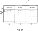
- Flow table 28 contains flow table entries (e.g., rows in the table) that have multiple fields (sometimes referred to as header fields).
- the fields in a packet that has been received by switch 14 can be compared to the fields in the flow table.
- Each flow table entry may have associated actions. When there is a match between the fields in a packet and the fields in a flow table entry, the corresponding action for that flow table entry may be taken.
- table 28 may have flow table entries (row) 68. Each flow table entry may be associated with header 70, action 72, and statistics 74. Headers 70 may each include multiple header fields 76. The action in each flow table entry indicates what action switch 14 is to perform on the packet when a match is detected between the fields in the packet and the corresponding fields in the header of that flow table entry. Switch 14 may maintain statistical data (counter values) in the statistics portion of flow table 28 that can be queried by controller server 18 when it is desired to obtain information on the performance of switch 14.
- the header fields in header 70 may include the following fields: ingress port (i.e., the identity of the physical port in switch 14 through which the packet is being received), Ethernet source address, Ethernet destination address, Ethernet type, virtual local area network (VLAN) id, VLAN priority, IP source address, IP destination address, IP protocol, IP ToS (type of service) bits, Transport source port / Internet Control Message Protocol (ICMP) Type (sometimes referred to as source TCP port), and Transport destination port / ICMP Code (sometimes referred to as destination TCP port).
- ingress port i.e., the identity of the physical port in switch 14 through which the packet is being received
- Ethernet source address i.e., Ethernet destination address, Ethernet type, virtual local area network (VLAN) id, VLAN priority, IP source address, IP destination address, IP protocol, IP ToS (type of service) bits
- Transport source port / Internet Control Message Protocol (ICMP) Type sometimes referred to as source TCP port
- Transport destination port / ICMP Code sometimes
- Each flow table entry is associated with zero or more actions that dictate how the switch handles matching packets. If no forward actions are present, the packet is preferably dropped.
- the actions that may be taken by switch 14 when a match is detected between packet fields and the header fields in a flow table entry may include the following actions: forward (e.g., ALL to send the packet out on all interfaces, not including the incoming interface, CONTROLLER to encapsulate and send the packet to the controller server, LOCAL to send the packet to the local networking stack of the switch, TABLE to perform actions in flow table 28, IN_PORT to send the packet out of the input port, NORMAL to process the packet with a default forwarding path that is supported by the switch using, for example, traditional level 2, VLAN, and level 3 processing, and FLOOD to flood the packet along the minimum spanning tree, not including the incoming interface).
- forward e.g., ALL to send the packet out on all interfaces, not including the incoming interface
- CONTROLLER to encapsulate and send the packet to the controller
- Additional actions that may be taken by switch 14 include: an enqueue action to forward a packet through a queue attached to a port and a drop action (e.g., to drop a packet that matches a flow table entry with no specified action).
- Modify-field actions may also be supported by switch 14. Examples of modify-field actions that may be taken include: Set VLAN ID, Set VLAN priority, Strip VLAN header, Modify Ethernet source MAC (Media Access Control) address, Modify Ethernet destination MAC address, Modify IPv4 source address, Modify IPv4 ToS bits, Modify transport destination port.
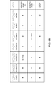
- FIG. 6B is an illustrative flow table having three flow table entries.
- the entries include fields with wildcards (e.g., "*" symbols). When a wildcard is present in a particular field, all incoming packets will be considered to form a "match" with respect to the field, regardless of the particular value of the field in the incoming packet.
- wildcards e.g., "*" symbols
- the entry of the first row of the FIG. 6B table directs the switch in which the flow table entry is operating to perform Ethernet switching. In particular, incoming packets with matching Ethernet destination addresses are forwarded to port 3.
- the entry of the second row of table of FIG. 6B illustrates how a switch may be configured to perform internet routing (i.e., packets are forwarded based on their destination IP address).
- the third row of the table of FIG. 6B contains an entry that illustrates how a switch may be configured to perform firewalling.
- a packet is received that has a destination IP port value of 80, that packet is dropped (i.e., the switch is configured to serve as a firewall that blocks port 80 traffic).
- Flow table entries of the type shown in FIG. 6B may be loaded into a switch 14 by controller server 18 during system setup operations or may be provided to a switch 14 from controller server 18 in real time in response to receipt and processing of packets at controller server 18 from switch 14.
- each switch can be provided with appropriate flow table entries to form a path through the network.
- controller server 18 may provide the first switch with the flow table entry of FIG. 6C and may provide the second switch with the flow table entry of FIG. 6D .
- packets with destination IP address 172.12.3.4 are received at the first switch, they are forwarded to the second switch in accordance with the "forward to port 3" action in the FIG. 6C table.
- packets with packets are received at the second switch, they are forwarded to the second end host that is connected to port 5 of the second switch in accordance with the "forward to port 5" action in FIG. 6D .
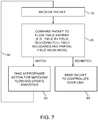
- switch 14 receives a packet on one of its ports (e.g., one of input-output ports 34 of FIG. 1 ).
- switch 14 compares the fields of the received packet to the fields of the flow table entries in the flow table 28 of that switch to determine whether there is a match.
- Some fields in a flow table entry may contain complete values (i.e., complete addresses).
- Other fields may contain wildcards (i.e., fields marked with the "don't care” wildcard character of "*").
- Yet other fields may have partially complete entries (i.e., a partial address that is partially wildcarded).
- Some fields may use ranges (e.g., by restricting a TCP port number to a value between 1 and 4096) and in effect use the range to implement a type of partial wildcarding.
- switch 14 can take into account whether or not each field in the flow table entry contains a complete value without any wildcarding, a partial value with wildcarding, or a wildcard character (i.e., a completely wildcarded field).
- switch 14 may send the packet to controller server 18 over link 16 (step 84).
- switch 14 may perform the action that is associated with that flow table entry and may update the counter value in the statistics field of that flow table entry (step 82). Processing may then loop back to step 78, so that another packet may be processed by switch 14, as indicated by line 86.
- a controller e.g., a controller server or other controllers implemented on computing equipment
- the controller may gather or monitor network information such as network topology or information associated with end hosts.
- the controller may include one or more controller servers or may be distributed throughout one or more of the switches.
- the controller may monitor the network locations of end hosts or monitor connections between switches in the network.
- the controller may reduce traffic load on the network by using the network information to control communications between end hosts.
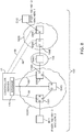
- FIG. 8 shows an illustrative network 100 with switches (e.g., or other packet processing systems) that may be controlled by controller server 18.
- network 100 may include switches SW1, SW2, SW3, SW4, SW5, SW6.
- Some of the switches may include controller clients and therefore be referred to as client switches (e.g., switches SW1, SW2, SW3, SW4, and SW5 may be referred to as client switches).
- Controller server 18 may communicate with the client switches via network paths 66 (e.g., to provide the client switches with instructions or receive information from the client switches).
- Some of the switches may lack controller clients and therefore be referred to as non-client switches (e.g., switch SW6 may be referred to as a non-client switch).
- Each switch may include respective physical ports (e.g., switch SW1 may include ports A, B, C, and D, switch SW5 may include ports E and F, etc.).
- End hosts EH1 and EH2 may communicate through the network by sending network traffic to respective ports to which they are coupled. For example, to communicate with end host EH2, end host EH1 may send a network packet to port D of client switch SW1. In this scenario, client switch SW1 may examine a corresponding flow table to determine whether or not a flow table entry exists for the network packet that was sent from end host EH1. Client switch SW1 may determine that no appropriate flow table entry exists (e.g., because controller server 18 has not yet generated a packet forwarding path through the client switches between end hosts EH1 and EH2). Client switch SW1 may then forward the network packet to controller server 18.
- client switch SW1 may examine a corresponding flow table to determine whether or not a flow table entry exists for the network packet that was sent from end host EH1. Client switch SW1 may determine that no appropriate flow table entry exists (e.g., because controller server 18 has not yet generated a packet forwarding path through the client switches between end hosts EH1 and EH2). Client switch SW1 may then forward the network packet to
- Controller server 18 may obtain information such as packet source and packet destination information from the network packet and use the information to generate a packet forwarding path for network packets between end hosts EH1 and EH2 (e.g., by sending appropriate flow table entries to each of the client switches associated with a packet forwarding path between end hosts EH1 and EH2). As an example, controller server 18 may generate a packet forwarding path through client switches SW1, SW3, SW2, SW4, and SW5.
- Network packets sent between end hosts include information relating to the end hosts.
- a network packet sent from end host EH1 to end host EH2 may include packet source information and packet destination information.
- the packet source information may include a source hardware address (e.g., a source MAC address or other hardware address that is associated with the source end host) and a source network address (e.g., a source IP address or other network protocol address corresponding to the source end host).
- the packet destination information may include a destination hardware address (e.g., a destination MAC address that corresponds to the destination end host) and a destination network address (e.g., a destination IP address corresponding to the destination end host).
- MAC addresses may sometimes be referred to as Ethernet hardware addresses.
- End host EH1 may have a MAC address of 2 and end host EH2 may have a MAC address of 1. These examples are merely illustrative. End host EH1 and end host EH2 may have any desirable MAC address (or other hardware addresses). If desired, the MAC addresses may be displayed in a separated hex format. For example, MAC address 1 may be displayed as 00:00:00:00:00:01 and MAC address 2 may be displayed as 00:00:00:00:00:02.
- End hosts may have incomplete knowledge of the network addresses of other end hosts.
- end host EH1 wishes to communicate with end host EH2, but only knows the IP address of end host EH2.
- end host EH1 To send network packets to end host EH2, end host EH1 must first discover the MAC address of end host EH2 (e.g., end host EH1 must obtain the MAC address of end host EH2 to form network packets with correct packet destination information).
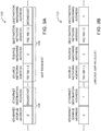
- end host EH1 may transmit the address resolution packet (ARP) request packet 122 of FIG. 9A .
- ARP address resolution packet
- ARP request packet 122 may include a source network address (e.g., an IP address) field, source hardware address (e.g., a MAC address) field, destination network address field, and destination hardware address field.
- End host EH1 may provide its own IP and MAC addresses in the source network address and source hardware address fields (i.e., 192.168.1.3 and 2, respectively).
- End host EH1 may provide the destination IP address of end host EH2 (i.e., 192.168.1.2) in the destination network address field and identify that ARP request packet 122 should be broadcasted to all MAC addresses (e.g., by providing a broadcast MAC address such as FF:FF:FF:FF:FF in the destination MAC address field).
- end host EH2 i.e., 192.168.1.2
- ARP request packet 122 should be broadcasted to all MAC addresses (e.g., by providing a broadcast MAC address such as FF:FF:FF:FF:FF in the destination MAC address field).
- ARP request packet 122 may be sent as an Ethernet frame (e.g., a data packet sent through Ethernet links between switches of network 100).
- the Ethernet frame may include ARP fields 128 and Ethernet header fields 126.
- ARP fields 128 may include the source network address field, source hardware address field, destination network address field, and destination hardware address field and may be formed as part of an Ethernet payload (e.g., a data portion of the Ethernet frame).
- Ethernet header fields 126 may include an Ethernet source address of 2 and a broadcast Ethernet destination address (e.g., a broadcast Ethernet address such as FF:FF:FF:FF:FF).
- the destination hardware address field of ARP fields 128 may be optional, as the Ethernet destination address may already indicate that ARP request packet 122 should be broadcasted to all end hosts in network 100.
- end host EH1 may flood network 100 with ARP requests. Each switch in network 100 that receives ARP request packet 122 may forward the packet to each port of that switch. Each end host that receives ARP request packet 122 may compare the destination IP address field of the packet with the IP address of that end host. When end host EH2 receives ARP request packet 122, end host EH2 may identify that the destination IP address field matches the IP address of end host EH2 and send an ARP reply packet that includes the MAC address of end host EH2 to end host EH1. In this way, end host EH1 may obtain address information necessary to send network packets to end host EH2.
- ARP request packet 122 may be referred to as a broadcast packet, because ARP request packet 122 may be forwarded to all end hosts in network 100 (e.g., ARP request packet 122 may be flooded throughout network 100 to each end host).
- Network packets such as ARP replies that are destined for a given end host may sometimes be referred to as unicast packets, because they are destined for a single end host.
- the flooding of ARP request packet 122 throughout network 100 may undesirably increase network load.
- the amount of network traffic generated by a first end host to discover the hardware address of a second end host may be related to the number of switches and end hosts in the network (e.g., because each switch that receives ARP request packet 122 may broadcast the packet to other switches and end hosts that are coupled to that switch) .
- controller server 18 may instruct client switches to forward ARP requests to controller server 18 instead of broadcasting the requests (e.g., by providing appropriate flow table entries to the client switches).
- controller server 18 may retrieve the destination IP address (and/or other packet information) from the ARP request packet.
- Controller server 18 may use information known about the topology of the network to identify a hardware address (e.g., MAC address) that corresponds to the destination IP address retrieved from the ARP request packet. For example, controller server 18 may maintain a database in storage 170 of end hosts that are known to be connected to network 100.
- the database may include entries that each identifies a respective end host by a corresponding IP address, hardware address, and the location of that end host within the network.
- end host EH1 of network 100 may be identified by a database entry including "IP address: 192.168.1.3, MAC address: 2, and location: port D of switch SW1.”
- the entries in the end host database may be updated to reflect current network attributes. For example, an entry corresponding to end host EH1 may be updated based on information retrieved from network packets sent from end host EH1 through the network.
- controller server 18 may convert the broadcast ARP request packet into a unicast ARP request and instruct client switches in network 100 to forward the unicast ARP request directly to the end host corresponding to identified MAC address (e.g., instead of flooding the network with the broadcast ARP request).
- FIG. 9B shows an illustrative unicast ARP request 123 that may be generated by controller server 18 from ARP request 122.
- unicast ARP request 123 may include an Ethernet destination address of 1 and a destination hardware address of 1.
- Unicast ARP request 123 may be generated from broadcast ARP request 122 by replacing the broadcast address used in the Ethernet destination address and destination hardware address fields with the hardware address of end host EH2 (e.g., the hardware address of the end host that would have replied to broadcast ARP request 122).
- Controller server 18 may instruct client switches in network 100 to forward unicast ARP request 123 directly to end host EH2 by providing the client switches with appropriate flow table entries that instruct the client switches to forward ARP request 123 along a network switch forwarding path from end host EH1 to end host EH2. If desired, controller server 18 may provide the client switches with flow table entries to forward corresponding ARP replies from end host EH2 to end host EH1. By converting broadcast ARP request 122 into a directed ARP request such as unicast ARP request 123, controller server 18 may reduce unnecessary network load and improve network performance, because fewer ARP request packets may be forwarded through the network.
- controller server 18 may provide unicast ARP request 123 to client switches in response to determining that end host EH2 is not known. For example, if controller server 18 cannot identify a MAC address that corresponds to the destination IP address of the ARP request packet, controller server 18 may convert the broadcast ARP request packet into unicast ARP request packet 123 and instruct client switch SW1 to forward the unicast ARP request from each of the ports of client switch SW1.
- controller server 18 may reduce network traffic associated with fulfilling the ARP request, because any network switches that have already discovered the location of end host EH2 may forward the ARP request directly to end host EH2 (e.g., instead of forwarding the ARP request to controller server 18 or broadcasting ARP requests).
- non-client switch SW6 may have discovered a route to end host EH2 by monitoring packets received at non-client switch SW6.
- client switches SW4 and SW5 may have already been provided flow table entries to route packets to end host EH2.
- the switches that have already discovered the location of end host EH2 may forward unicast ARP request 123 directly to end host EH2.
- controller server 18 may instruct client switches in network 100 to forward ARP requests only to ports that are not coupled to other client switches.
- Controller server 18 may identify client switches that are coupled to at least one end host or non-client switch using network topology information that is gathered during setup of network 100 or is continuously gathered during operation of network 100.
- controller server 18 may provide ARP requests (e.g., ARP request 122 or 123) to the identified client switches and instruct those client switches to send the ARP requests from ports that are not coupled to other client switches (e.g., to ports coupled to non-client switches or end hosts).
- ARP requests e.g., ARP request 122 or 123
- controller server 18 may reduce network traffic associated with fulfilling the ARP requests (e.g., because the ARP requests may not be sent between client switches).
- controller server 18 may generate an ARP reply for the ARP request packet and send the controller-generated ARP reply to the end host that sent the ARP request packet (e.g., instead of forwarding the ARP request packet to the ARP destination end host).
- FIG. 10 shows an illustrative controller-generated ARP reply packet 124A that may be provided by controller server 18 to end host EH1 in response to ARP request 122 of FIG. 9A .
- controller-generated ARP reply 124A may include Ethernet header fields 126 and ARP information fields 128.
- Ethernet header fields 126 may include an Ethernet source address of 1 (e.g., the hardware address of end host EH2) and an Ethernet destination address of 2 (e.g., the hardware address of end host EH1).
- ARP information fields 128 may be formed as part of an Ethernet payload or data portion and may include a source network address of 192.168.1.2, a source hardware address of 1, a destination network address of 192.168.1.3, and a destination hardware address of 2.
- Controller-generated ARP reply 124A may be identical to the ARP reply that would have been sent from end host EH2 to end host EH1 (e.g., as if end host EH2 had generated the ARP reply).
- ARP reply packet 124A may be sent from controller server 18 to end host EH1 through a client switch that is coupled to end host EH1 (e.g., switch SW1), through a client switch that is coupled to end host EH2, or through any desirable client switch in network 100 that can forward network packets to end host EH1.
- controller server 18 may send ARP reply packet 124A to switch SW1 via network path 66 and instruct switch SW1 to forward the packet to end host EH1 via port D.
- controller server 18 may reduce unnecessary network traffic associated with broadcasting of ARP request 122 by switches in network 100.
- Controller server 18 may maintain a database of end hosts by monitoring traffic on network 100 to add and modify entries in the database. For example, controller server 18 may monitor network packets such as ARP request packets that are sent from any given end host to identify whether the end host is known (e.g., an entry for that end host exists in the database) or whether a corresponding entry for that end host should be updated or added to the database. The network packets may be monitored by retrieving packet information such as header fields from the network packets.
- ARP request packets such as ARP request packets that are sent from any given end host to identify whether the end host is known (e.g., an entry for that end host exists in the database) or whether a corresponding entry for that end host should be updated or added to the database.
- the network packets may be monitored by retrieving packet information such as header fields from the network packets.
- Controller server 18 may organize client switches in network 100 into clusters (groups) of client switches (sometimes referred to as client switch clusters). Client switch clusters may be separated by non-client switches (e.g., a first client switch cluster may be separated from a second client switch cluster by one or more non-client switches). Switches SW1, SW2, and SW3 may be organized into a first client switch cluster 102A and switches SW4 and SW5 may be organized into a second client switch cluster 102B. Client switch clusters 102A and 102B may be separated by non-client switch SW6.
- a client switch cluster may include end hosts that are coupled to the client switches of the cluster (e.g., coupled directly to the client switches or coupled through non-client switches).
- a client switch cluster associated with an end host that sends a network packet may be referred to as a source client switch cluster or source cluster.
- a client switch cluster associated with an end host that receives a network packet may be referred to as a destination client switch cluster or destination cluster.
- Client switch clusters may be coupled to non-client switches via ports of client switches within the client switch clusters.
- client switch cluster 102A may be coupled to non-client switch SW6 via port X and client switch cluster 102B may be coupled to client switch SW6 via port Y.
- the ports at which non-client switches are coupled to the client switch clusters may be referred to as attachment points or cluster interface ports.
- port X may be referred to as cluster interface port 108A of cluster 102A and port Y may be referred to as cluster interface port 108B of cluster 102B.
- Client switches in a given client switch cluster may be coupled to other client switches in that client switch cluster via forwarding paths that do not include non-client switches.
- client switch SW1 is coupled to client switch SW2 through client switch SW3.
- Client switches in different client switch clusters may be coupled via network paths that include non-client switches.
- client switch SW2 may communicate with client switch SW4 by sending network packets through non-client switch SW6.
- controller server 18 may determine forwarding paths through client switches in the network using ARP requests that are sent by end hosts. Controller server 18 may use forwarding paths determined in this way to control client switches in network 100. For example, controller server 18 may use a forwarding path determined using an ARP request from a first end host to a second end host to provide appropriate flow table entries to the client switches so that future network traffic between the first and second end hosts is forwarded along the determined forwarding path through the client switches.
- controller server 18 does not know the network topology between cluster 102A and 102B (e.g., controller server 18 may have limited information regarding non-client switches such as SW6, because controller server 18 is unable to control non-client switches).
- controller server 18 it may be desirable for controller server 18 to use an ARP request that is broadcasted from end host EH1 to end host EH2 to help identify the network topology between clusters 102A and 102B (e.g., to determine forwarding paths from end host EH1 to end host EH2).
- controller server 18 may convert the broadcast ARP request into a unicast ARP request and instruct switches in the first client switch cluster to send the unicast ARP request from ports that are coupled to non-client switches.
- the ports in a given client switch cluster that are coupled to non-client switches may be referred to as attachment points or cluster interface ports, because that client switch cluster may be coupled to non-client switches at those ports.
- Controller server 18 may instruct client switches in the first client switch cluster to send the unicast ARP request to non-client switches by providing packet forwarding rules (e.g., flow table entries) that direct the client switches in the first client switch cluster to forward the unicast ARP request from ports that are coupled to non-client switches. If desired, controller server 18 may bypass intermediate client switches in the first client switch cluster by directly providing client switches in the first client switch cluster that are coupled to non-client switches with the unicast ARP request and instructing those client switches to forward the unicast ARP request to the non-client switches.
- packet forwarding rules e.g., flow table entries
- controller server 18 may convert broadcast ARP request 122 into unicast ARP request 123 and instruct client switch SW2 of network 100 to forward unicast ARP request 123 to non-client switch SW6 via port X.
- non-client switch SW6 may receive unicast ARP request 123 and forward the unicast ARP request to client switch SW4 (e.g., after identifying which port of non-client switch SW6 is associated with end host EH2).
- Client switch SW4 may receive unicast ARP request 123 from non-client switch SW6 and forward the request to controller server 18.
- controller server 18 may determine that a packet forwarding path between client switch cluster 102A and client switch cluster 102B exists from port X of switch SW2 to port Y of switch SW4. Controller server 18 may then direct the client switches to forward unicast ARP request 123 along the identified packet forwarding path to end host EH2 (e.g., so that end host EH2 can generate a corresponding ARP reply) or provide end host EH1 with a controller-generated ARP reply.
- end host EH2 e.g., so that end host EH2 can generate a corresponding ARP reply
- Non-client switches such as switch SW6 of network 100 may use ARP requests to associate hardware addresses (e.g., MAC addresses) with switch ports.
- a non-client switch that receives a controller-generated ARP reply at a given port may associate the Ethernet source address of the ARP reply with the given port.
- Future network packets destined for that Ethernet address may be sent by the non-client switch from the given port, because the non-client switch assumes that the end host corresponding to that Ethernet address can be reached via that port.
- the non-client switches may incorrectly learn associations from controller-generated ARP replies 124.
- controller server 18 may form controller-generated ARP replies with the Ethernet source address set to a hardware address that is reserved by controller server 18.
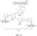
- FIG. 11 shows an illustrative scenario in which controller server 18 may form a controller-generated ARP reply with a reserved hardware address.
- network packets transmitted from end host EH1 to end host EH2 must first traverse non-client switch SW9 (e.g., because end host EH1 is coupled to non-client switch SW9).
- end host EH1 may send ARP request 122 of FIG. 9A to non-client switch SW9.
- non-client switch SW9 may broadcast ARP request 122 by forwarding the request to each switch that is coupled to non-client switch SW9 (i.e., client switches SW11 and SW10).
- client switches SW10 and SW11 may each forward ARP request 122 to controller server 18 via network paths 66.
- Controller server 18 may be unable to differentiate between ARP requests 122 that are received from client switches SW11 and SW10, because both requests may originate from non-client switch SW9. If controller server 18 were to respond to ARP requests received at client switches SW11 and SW10 from end host EH1 with controller-generated ARP replies that have the Ethernet source address of end host EH2, non-client switch SW9 can potentially learn incorrect forwarding paths for network traffic that is destined for end host EH2 (e.g., non-client switch SW9 may incorrectly associate end host EH2 with client switch SW11).
- controller server 18 may use a reserved hardware address for the Ethernet source address field of a controller-generated ARP reply.
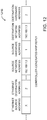
- FIG. 12 shows an illustrative controller-generated ARP reply 124B that may be generated by controller server 18 in response to an ARP request 122 that is broadcasted by end host EH1 of FIG. 11 .
- controller-generated ARP reply 124B may include a reserved hardware address X used in the Ethernet source address field.
- Reserved hardware address X may be a hardware address (e.g., a MAC address) that is not used by other devices (e.g., switches, end hosts, etc.) in network 100.
- controller server 18 may prevent non-client switches such as switch SW9 of FIG. 11 from learning incorrect forwarding paths from controller-generated ARP reply 124B. For example, if non-client switch SW9 receives controller-generated ARP reply packets 124B from client switches SW10 and SW11, non-client switch SW9 may associate the reserved hardware address X with ports of switch SW9 that are coupled to client switches SW10 and SW11. The associations that are learned by non-client switch SW9 may not affect the forwarding of normal traffic through network 150, because normal traffic may not be sent to reserved hardware address X (e.g., because reserved hardware address X is not associated with any end host).
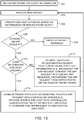
- controller server 18 may perform the illustrative steps of the flowchart of FIG. 13 .
- controller server 18 may gather network topology information.
- the network topology information may include connections between network switches, end host information such as network addresses and hardware addresses, or other network information.
- the network topology information may be obtained by instructing client switches in the network to forward network information such as switch capabilities and connections.
- controller server 18 may instruct client switches to send link layer discovery protocol (LLDP) messages to discover connections between ports of client switches.
- Controller server 18 may use the network topology information to organize client switches into client switch clusters that are separated by non-client switches. Controller server 18 may gather network topology during initial setup of the network and/or continuously during operation of the network (e.g., while network packets are forwarded through the network).
- LLDP link layer discovery protocol
- controller server 18 may receive a new packet.
- the new packet may be received from an end host via a client switch that forwards the new packet to controller server 18.
- controller server 18 may update an end host database based on information retrieved from the packet.
- the end host database may include entries for each known end host in the network. Each entry may include end host address information such as a hardware address (e.g., MAC or other Ethernet address) and a network address (e.g., IP address or other protocol addresses).
- Controller server may retrieve the hardware address and network address of an end host by retrieving source and/or destination addresses from header fields in the packet (as an example).
- controller server 18 may identify whether the packet is an ARP request. Controller server 18 may identify an ARP request packet based on information retrieved from the packet (e.g., header fields retrieved from the packet that identifies the packet as an ARP request). If controller server 18 identifies that the new packet is an ARP request packet, the operations of step 210 may be performed. If controller server 18 identifies that the new packet is not an ARP request packet, the operations of step 208 may be performed.
- controller server 18 may process the new packet normally. For example, controller server 18 may generate packet forwarding paths for the new packet (e.g., by providing flow table entries to client switches in the network that instruct the client switches to forward the new packet from a packet source to a packet destination).
- packet forwarding paths for the new packet e.g., by providing flow table entries to client switches in the network that instruct the client switches to forward the new packet from a packet source to a packet destination.
- controller server 18 may identify whether or not the destination end host of the ARP packet is known (e.g., whether or not a corresponding hardware address is known for a network address retrieved from the destination network address field of the ARP packet). Controller server 18 may use information stored in end host databases such as generated in step 204 to identify whether the destination end host of the ARP packet is known. If the ARP destination end host is unknown, controller server 18 may perform the operations of step 212. If the ARP destination end host is known, controller server 18 may perform the operations of step 214.
- controller server 18 may use network topology information to optimize the discovery of the destination end host specified by the ARP request.
- controller server 18 may instruct client switches to broadcast the ARP request, convert the ARP request into a unicast ARP request destined for the destination end host, or forward the ARP request from switch ports that are on the edge of the network (e.g., from switch ports that are not coupled to other switches in the network).
- controller server 18 may process the ARP request based on network topology information.
- controller server 18 may form a controller-generated ARP request based on information retrieved from the end host database or instruct switches to forward the ARP request to the destination end host.
- controller server 18 may convert the ARP request into a unicast ARP request such as unicast ARP request 123 of FIG. 9B and direct client switches in the network to forward the unicast ARP request to the ARP destination end host.
- controller server 18 may form a controller-generated ARP reply based on the ARP request (e.g., controller-generated ARP reply 124A of FIG. 10 or controller-generated ARP request 124B of FIG. 12 ).
- Controller server 18 may provide controller-generated ARP replies to a client switch that is coupled to the end host that sent the ARP request (e.g., a client switch coupled directly to the end host or coupled to the end host through non-client switches).
- step 214 of FIG. 13 may include the steps of FIG. 14 .
- controller server 18 may identify whether or not network topology information between the ARP source and destination end hosts is known. For example, controller server 18 may identify switch clusters that are associated with the source and destination end hosts. As another example, controller server 18 may determine a forwarding path through the network (e.g., through client switches and non-client switches) from the source end host to the destination end host. In this scenario, the forwarding path may include a list of ports and associated switches through which packets may flow from the source end host to the destination end host.
- step 224 may be performed. If the network topology between the source and destination end hosts is known, the operations of step 224 may be performed. If the network topology between the source and destination end hosts is not known (e.g., if controller server 18 is unable to determine a forwarding path between the two end hosts), the operations of step 226 may be performed.
- controller server 18 may form a controller-generated ARP reply that corresponds to the ARP request and provide the controller-generated ARP reply to the source end host.
- controller server 18 may form controller-generated ARP reply 124A of FIG. 10 or controller-generated ARP reply 124B of FIG. 12 .
- Controller server 18 may provide the controller-generated ARP reply to the source end host by sending the reply to a client switch that is coupled to the source end host (e.g., via network paths 66) and directing the client switch to send the reply to the source end host.
- controller server 18 may identify whether or not source cluster interface ports are known. In other words, controller server 18 may identify whether or not the client switch cluster associated with the source end host is coupled to non-client switches at known interface ports. For example, controller server 18 may identify interface port 108A for source cluster 102A in network 100 of FIG. 8 . Known interface ports for a given client switch cluster may be retrieved from a database on controller server 18 or determined from network topology information.
- controller server 18 If controller server 18 is unable to identify any source cluster interface ports (e.g., if no interface ports exist for the source cluster or if controller server 18 does not yet know the interface ports), the operations of step 228 may be performed. If controller server 18 is able to identify a source cluster interface port, the operations of step 230 may be performed.
- controller server 18 may broadcast the ARP request.
- controller server 18 may instruct client switches in the network to broadcast the ARP request to all ports or convert the ARP request into a unicast ARP request and instruct a client switch in the network to send the unicast ARP request from each port of that client switch.
- controller server 18 form one or more unicast ARP requests from the received ARP request and deliver the unicast ARP requests at identified source cluster interface ports. For example, controller server 18 may convert a broadcast ARP request into a unicast ARP request. Controller server 18 may deliver the unicast ARP requests by instructing client switches associated with the identified interface ports to send the unicast ARP requests from the interface ports (e.g., from the ports that are coupled to non-client switches).
- controller server 18 may reduce network traffic and help improve network performance.
- controller server 18 may process any desirable network packets that request hardware address information of end hosts in a network.
- controller server 18 may process packets sent using the neighbor discovery protocol (NBP) that request hardware addresses that correspond to Internet Protocol Version 6 (IPv6) addresses or may process packets that request hardware addresses that correspond to other protocols or other versions of the Internet Protocol.
- NBP neighbor discovery protocol
- IPv6 Internet Protocol Version 6
- controller server 18 to control network switches is merely illustrative. If desired, any type of controller (e.g., a controller implemented on computing equipment) that controls a network of packet forwarding systems may be used to process network packets such as ARP requests (e.g., to perform the steps of the flowcharts of FIGS. 13 and 14 ).
- ARP requests e.g., to perform the steps of the flowcharts of FIGS. 13 and 14 .
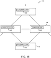
- FIG. 15 shows an illustrative example in which controllers 302 may be distributed on switches 14 throughout network 300. Controllers 302 may be distributed on some or all of network switches 14. Controller clients such as controller client 30 may communicate with one or more of controllers 302 via network communications links (e.g., controllers 302 may send instructions to controller client 30 via the communications links). Controllers 302 may communicate with each other to collectively control switches 14 or may individually control switches 14.
- controllers 302 may collectively control network 300 by communicating with each other. Controllers 302 may share information relating to network topology, network traffic, end hosts that are coupled to switches 14, etc. By sharing network information, controllers 302 may be able to gather network topology information and use the network topology information to process ARP packets or other packets that request hardware address information.
- a method of fulfilling hardware address requests in a network of switches where the switches are organized into at least first and second groups of switches that are controlled by a controller and that are isolated from each other by at least one intervening switch that is not controlled by the controller, the method is provided that with the controller, identifying whether a network packet received from a switch in the first group of switches is an Address Resolution Protocol request packet; and with the controller, directing a given switch from the first group of switches to send an Address Resolution Protocol request to the intervening switch at least partly in response to identifying that the network packet is an Address Resolution Protocol request packet.
- identifying whether the network packet is being sent from a packet source associated with the first group of switches to a packet destination associated with the second group of switches including the controller, identifying whether the network packet is being sent from a packet source associated with the first group of switches to a packet destination associated with the second group of switches; and in response to identifying that the network packet is being sent from a packet source associated with the first group of switches to a packet destination associated with the second group of switches, generating a modified version of the Address Resolution Protocol request packet, directing the given switch from the first group of switches to send the Address Resolution Protocol request to the intervening switch includes directing the given switch to send the modified version of the Address Resolution Protocol request packet.
- the Address Resolution Protocol request packet has a destination address header field and generating a modified version of the Address Resolution Protocol request packet includes storing the hardware address of the second end host in the destination address header field of the Address Resolution Protocol request packet.
- the method includes the first and second groups of switches with packet forwarding rules that form a packet forwarding path between the packet source and the packet destination.
- a method of using a controller to control network traffic through switches in a network includes the controller, identifying whether a network packet sent from a first end host is requesting a hardware address of a second end host; in response to identifying that the network packet is requesting the hardware address of the second end host, retrieving the hardware address of the second end host from a database using the controller; and with the controller, providing the hardware address retrieved from the database to the first end host.
- identifying that the network packet is requesting the hardware address of the second end host includes identifying that the network packet is an Address Resolution Protocol request by retrieving packet information from header fields of the network packet.
- providing the hardware address to the first end host includes the controller, forming an Address Resolution Protocol reply packet that corresponds to the network packet; and sending the Address Resolution Protocol reply packet to the first end host.
- the method includes with the controller, sending the network packet to the second end host; with the controller, receiving a reply packet from the second end host; and with the controller, sending the reply packet to the first end host.
- sending the network packet to the second end host includes with the controller, providing flow table entries to the switches that direct the switches to forward the network packet from the first end host to the second end host.
- forming the Address Resolution Protocol reply packet that corresponds to the network packet includes with the controller, forming the Address Resolution Protocol reply packet with an Ethernet source address that is reserved for the controller and with the hardware address of the second end host.
Landscapes
- Engineering & Computer Science (AREA)
- Computer Networks & Wireless Communication (AREA)
- Signal Processing (AREA)
- Data Exchanges In Wide-Area Networks (AREA)
Claims (7)
- Procédé d'utilisation d'un contrôleur (18) pour commander des commutateurs dans un réseau (100), le procédé comprenant les étapes ci-dessous consistant à :avec le contrôleur, collecter des informations de topologie de réseau à partir des commutateurs ;avec le contrôleur, recevoir un paquet de réseau qui est envoyé à partir d'un premier hôte d'extrémité (EH1) et qui est acheminé au contrôleur par un commutateur donné des commutateurs ;avec le contrôleur, identifier si le paquet de réseau qui est envoyé à partir du premier hôte d'extrémité (EH1) et qui est acheminé au contrôleur par ledit commutateur donné des commutateurs est un paquet de demande de protocole de résolution d'adresse demandant une adresse matérielle d'un second hôte d'extrémité (EH2) ; eten réponse à l'identification que le paquet de réseau demande l'adresse matérielle du second hôte d'extrémité, traiter le paquet de réseau avec le contrôleur en utilisant les informations de topologie de réseau collectées, dans lequel l'étape de traitement du paquet de réseau comprend l'étape ci-dessous consistant à :
identifier si l'adresse matérielle du second hôte d'extrémité (EH2) est connue, et caractérisé en ce que le contrôleur met en oeuvre les étapes ci-dessous consistant à :
en réponse à l'identification que l'adresse matérielle du second hôte d'extrémité (EH2) est inconnue, ordonner aux commutateurs d'acheminer le paquet de réseau à partir de ports de commutateurs sur un bord du réseau. - Procédé selon la revendication 1, dans lequel l'étape consistant à identifier si le paquet de réseau demande l'adresse matérielle du second hôte d'extrémité (EH2) comprend l'étape ci-dessous consistant à :
extraire des informations de paquet de champs d'en-tête de paquet du paquet de réseau. - Procédé selon la revendication 1, dans lequel les commutateurs présentent des ports, et dans lequel l'étape de collecte d'informations de topologie de réseau à partir des commutateurs comprend l'étape ci-dessous consistant à :
ordonner aux commutateurs d'envoyer des paquets de protocole de découverte de couche de liaison à partir des ports. - Procédé selon la revendication 1, comprenant en outre l'étape ci-dessous consistant à :
stocker des informations d'adresse source extraites du paquet de réseau dans une base de données d'hôtes d'extrémité. - Procédé selon la revendication 4, comprenant en outre l'étape ci-dessous consistant à :
identifier si l'adresse matérielle du second hôte d'extrémité (EH2) est connue, en examinant des informations d'adresse source précédemment stockées dans la base de données d'hôtes d'extrémité. - Procédé selon la revendication 5, comprenant en outre l'étape ci-dessous consistant à :
en réponse à l'identification que l'adresse matérielle du second hôte d'extrémité (EH2) est connue, former une réponse de protocole ARP générée par contrôleur (124A) avec le contrôleur (18). - Procédé selon la revendication 1, dans lequel l'étape de traitement du paquet de réseau avec le contrôleur (18) comprend les étapes ci-dessous consistant à :sur la base des informations de topologie de réseau, identifier si un chemin d'acheminement de paquets à travers les commutateurs entre le premier hôte d'extrémité et le second hôte d'extrémité est connu ; eten réponse à l'identification que le chemin d'acheminement de paquets est connu, former une réponse de protocole ARP générée par contrôleur (124A) avec le contrôleur ; etfournir la réponse de protocole ARP générée par contrôleur au premier hôte d'extrémité (EH1).
Applications Claiming Priority (2)
| Application Number | Priority Date | Filing Date | Title |
|---|---|---|---|
| US13/252,966 US10142160B1 (en) | 2011-10-04 | 2011-10-04 | System and methods for managing network hardware address requests with a controller |
| PCT/US2012/058587 WO2013052564A2 (fr) | 2011-10-04 | 2012-10-04 | Système et procédés de gestion des demandes d'adresse matérielle de réseau comprenant un contrôleur |
Publications (2)
| Publication Number | Publication Date |
|---|---|
| EP2748992A2 EP2748992A2 (fr) | 2014-07-02 |
| EP2748992B1 true EP2748992B1 (fr) | 2018-08-22 |
Family
ID=47080820
Family Applications (1)
| Application Number | Title | Priority Date | Filing Date |
|---|---|---|---|
| EP12778869.3A Not-in-force EP2748992B1 (fr) | 2011-10-04 | 2012-10-04 | Procédé de gestion des demandes d'adresse matérielle de réseau comprenant un contrôleur |
Country Status (4)
| Country | Link |
|---|---|
| US (1) | US10142160B1 (fr) |
| EP (1) | EP2748992B1 (fr) |
| JP (1) | JP5837989B2 (fr) |
| WO (1) | WO2013052564A2 (fr) |
Families Citing this family (31)
| Publication number | Priority date | Publication date | Assignee | Title |
|---|---|---|---|---|
| US10411998B1 (en) * | 2012-12-27 | 2019-09-10 | Sitting Man, Llc | Node scope-specific outside-scope identifier-equipped routing methods, systems, and computer program products |
| US10212076B1 (en) | 2012-12-27 | 2019-02-19 | Sitting Man, Llc | Routing methods, systems, and computer program products for mapping a node-scope specific identifier |
| US10397101B1 (en) * | 2012-12-27 | 2019-08-27 | Sitting Man, Llc | Routing methods, systems, and computer program products for mapping identifiers |
| US10397100B1 (en) * | 2012-12-27 | 2019-08-27 | Sitting Man, Llc | Routing methods, systems, and computer program products using a region scoped outside-scope identifier |
| US10404582B1 (en) * | 2012-12-27 | 2019-09-03 | Sitting Man, Llc | Routing methods, systems, and computer program products using an outside-scope indentifier |
| US10419335B1 (en) * | 2012-12-27 | 2019-09-17 | Sitting Man, Llc | Region scope-specific outside-scope indentifier-equipped routing methods, systems, and computer program products |
| US10411997B1 (en) * | 2012-12-27 | 2019-09-10 | Sitting Man, Llc | Routing methods, systems, and computer program products for using a region scoped node identifier |
| US10904144B2 (en) | 2012-12-27 | 2021-01-26 | Sitting Man, Llc | Methods, systems, and computer program products for associating a name with a network path |
| US10404583B1 (en) * | 2012-12-27 | 2019-09-03 | Sitting Man, Llc | Routing methods, systems, and computer program products using multiple outside-scope identifiers |
| US10447575B1 (en) | 2012-12-27 | 2019-10-15 | Sitting Man, Llc | Routing methods, systems, and computer program products |
| CN104158745B (zh) * | 2013-05-13 | 2018-11-06 | 南京中兴新软件有限责任公司 | 一种实现数据包转发的方法及系统 |
| WO2016114750A1 (fr) * | 2015-01-12 | 2016-07-21 | Hewlett Packard Enterprise Development Lp | Informations de couche liaison de données |
| US10798048B2 (en) * | 2015-04-07 | 2020-10-06 | Nicira, Inc. | Address resolution protocol suppression using a flow-based forwarding element |
| CN108028801B (zh) | 2015-07-27 | 2021-02-23 | 华为技术有限公司 | 一种基于sdn的arp实现方法及装置 |
| US11128566B2 (en) | 2016-04-27 | 2021-09-21 | Nec Corporation | Method for controlling a network |
| CN107547293B (zh) * | 2016-06-29 | 2020-09-08 | 新华三技术有限公司 | 一种流路径探测方法和装置 |
| CN107666428B (zh) * | 2016-07-28 | 2020-03-06 | 新华三技术有限公司 | 静默设备探测方法以及装置 |
| US10797959B2 (en) * | 2017-08-11 | 2020-10-06 | Quanta Computer Inc. | LLDP based rack management controller |
| US10873476B2 (en) | 2018-12-31 | 2020-12-22 | Big Switch Networks Llc | Networks with multiple tiers of switches |
| US10855644B1 (en) | 2019-09-09 | 2020-12-01 | Vmware, Inc. | Address resolution protocol entry verification |
| US11496437B2 (en) * | 2020-04-06 | 2022-11-08 | Vmware, Inc. | Selective ARP proxy |
| US11740919B2 (en) * | 2020-05-18 | 2023-08-29 | Dell Products L.P. | System and method for hardware offloading of nested virtual switches |
| CN114095508A (zh) * | 2020-07-31 | 2022-02-25 | 南京理工大学 | 一种同交换机下p2p传输的方法 |
| CN111935334B (zh) * | 2020-08-14 | 2022-09-20 | 株洲市慧纳科技有限责任公司 | 智能分配网络地址的方法、系统、服务器及可读存储介质 |
| US11805101B2 (en) | 2021-04-06 | 2023-10-31 | Vmware, Inc. | Secured suppression of address discovery messages |
| JP2025507288A (ja) | 2022-02-02 | 2025-03-18 | オラクル・インターナショナル・コーポレイション | 異なるクラウドサービスプロバイダにわたるアイデンティティの伝搬 |
| WO2023150522A1 (fr) * | 2022-02-02 | 2023-08-10 | Oracle International Corporation | Architecture de liaison de réseau améliorée pour une latence de bout en bout améliorée dans une communication entre différents environnements en nuage |
| JP2025506396A (ja) | 2022-02-02 | 2025-03-11 | オラクル・インターナショナル・コーポレイション | 異なるクラウド環境間の通信を可能にするためのネットワーク技術 |
| US12204955B2 (en) | 2022-02-02 | 2025-01-21 | Oracle International Corporation | Multi-cloud infrastructure-database adaptor |
| EP4283946A1 (fr) * | 2022-05-23 | 2023-11-29 | Telia Company AB | Gestion d'établissement d'une connexion de communication |
| JP2025535771A (ja) | 2022-10-14 | 2025-10-28 | オラクル・インターナショナル・コーポレイション | マルチクラウドインフラストラクチャにおけるsaasアプリケーションのためのネットワークリンクの確立 |
Family Cites Families (40)
| Publication number | Priority date | Publication date | Assignee | Title |
|---|---|---|---|---|
| JP3654554B2 (ja) | 1997-11-21 | 2005-06-02 | 株式会社小松製作所 | ネットワークシステム及びdhcpサーバ選択方法 |
| US6640251B1 (en) | 1999-03-12 | 2003-10-28 | Nortel Networks Limited | Multicast-enabled address resolution protocol (ME-ARP) |
| US7318089B1 (en) | 1999-09-30 | 2008-01-08 | Intel Corporation | Method and apparatus for performing network-based control functions on an alert-enabled managed client |
| US7231660B1 (en) | 1999-11-25 | 2007-06-12 | International Business Machines Corporation | Method and system for preventing unauthorized server interference in an internet protocol network |
| WO2002061599A1 (fr) | 2001-01-25 | 2002-08-08 | Crescent Networks, Inc. | Extension de protocole de resolution d'adresse (arp) pour reseaux virtuels a protocole internet (ip) |
| US8046452B2 (en) | 2001-03-08 | 2011-10-25 | British Telecommunications Public Limited Company | Inter-network address translator that is separately addressable from address alias assignment process |
| US7072354B1 (en) | 2001-10-03 | 2006-07-04 | Cisco Technology, Inc. | Token registration of managed devices |
| WO2003037009A1 (fr) | 2001-10-23 | 2003-05-01 | Meshnetworks, Inc. | Systeme et procede permettant d'obtenir un protocole de resolution d'adresse optimise en ce qui concerne l'encombrement, pour des reseaux ad-hoc sans fil |
| US7213065B2 (en) | 2001-11-08 | 2007-05-01 | Racemi, Inc. | System and method for dynamic server allocation and provisioning |
| US7337224B1 (en) | 2002-10-24 | 2008-02-26 | Cisco Technology, Inc. | Method and apparatus providing policy-based determination of network addresses |
| US7386629B2 (en) | 2003-06-30 | 2008-06-10 | Intel Corporation | System and method for synchronous configuration of DHCP server and router interfaces |
| JP3838437B2 (ja) | 2003-09-26 | 2006-10-25 | 日本電気株式会社 | ネットワークスイッチ及びその動作方法、並びにブレードサーバ |
| JP2006020085A (ja) | 2004-07-01 | 2006-01-19 | Fujitsu Ltd | ネットワークシステム、ネットワークブリッジ装置、ネットワーク管理装置およびネットワークアドレス解決方法 |
| US7920577B2 (en) | 2004-07-08 | 2011-04-05 | Avaya Communication Israel Ltd. | Power saving in wireless packet based networks |
| US7729284B2 (en) | 2005-01-19 | 2010-06-01 | Emulex Design & Manufacturing Corporation | Discovery and configuration of devices across an Ethernet interface |
| DE102005006889B4 (de) | 2005-02-15 | 2007-01-11 | Siemens Ag | Verfahren, Kommunikationsanordnung und Kommunikationsvorrichtung zum Einrichten einer Kommunikationsbeziehung in zumindest einem Kommunikationsnetz |
| US7756976B2 (en) | 2005-03-18 | 2010-07-13 | Hewlett-Packard Development Company, L.P. | Systems and methods for denying rogue DHCP services |
| US7937494B2 (en) | 2005-09-01 | 2011-05-03 | Cisco Technology, Inc. | Methods and apparatus for processing a DHCP request using rule-based classification |
| EP1780943A1 (fr) | 2005-10-31 | 2007-05-02 | Hewlett-Packard Development Company, L.P. | Découverte de ISO couche-2 topologie |
| US8966018B2 (en) | 2006-05-19 | 2015-02-24 | Trapeze Networks, Inc. | Automated network device configuration and network deployment |
| US20070286209A1 (en) | 2006-06-12 | 2007-12-13 | Research In Motion Limited | System and method for handling address resolution protocol requests |
| JP4882555B2 (ja) | 2006-07-07 | 2012-02-22 | 双葉電子工業株式会社 | 無線ブリッジ通信機 |
| WO2008031361A1 (fr) | 2006-09-11 | 2008-03-20 | 3Dsp Corporation | Système multi-passerelle et procédés associés |
| US20080101381A1 (en) | 2006-10-25 | 2008-05-01 | Mediatek Inc. | Address resolution protocol (arp) cache management methods and devices |
| US20080189769A1 (en) | 2007-02-01 | 2008-08-07 | Martin Casado | Secure network switching infrastructure |
| US9419867B2 (en) | 2007-03-30 | 2016-08-16 | Blue Coat Systems, Inc. | Data and control plane architecture for network application traffic management device |
| EP2597816B1 (fr) * | 2007-09-26 | 2019-09-11 | Nicira Inc. | Système d'exploitation de réseau pour la gestion et la sécurisation des réseaux |
| US8099764B2 (en) | 2007-12-17 | 2012-01-17 | Microsoft Corporation | Secure push and status communication between client and server |
| WO2009140625A1 (fr) | 2008-05-15 | 2009-11-19 | Harris Stratex Networks Operating Corporation | Systèmes et procédés pour le routage de données distribuées dans un réseau sans fil |
| US8238315B2 (en) | 2008-09-16 | 2012-08-07 | Marvell World Trade Ltd. | Rapid local address assignment for wireless communication networks |
| KR101352852B1 (ko) | 2008-09-30 | 2014-01-20 | 삼성전자주식회사 | Dhcp를 이용한 화상형성장치의 ip 주소 할당 방법, 그 화상형성장치, 및 dhcp를 이용한 ip주소 할당 시스템 |
| US7957374B2 (en) * | 2008-10-22 | 2011-06-07 | Fortinet, Inc. | Mechanism for enabling layer two host addresses to be shielded from the switches in a network |
| US8588082B2 (en) | 2009-09-23 | 2013-11-19 | Ixia | Network testing using control plane and data plane convergence |
| US20120314605A1 (en) | 2010-03-05 | 2012-12-13 | Ippei Akiyoshi | Communication system, path control apparatus, packet forwarding apparatus, and path control method |
| US8989187B2 (en) * | 2010-06-04 | 2015-03-24 | Coraid, Inc. | Method and system of scaling a cloud computing network |
| US20130024553A1 (en) | 2011-07-18 | 2013-01-24 | Cisco Technology, Inc. | Location independent dynamic IP address assignment |
| US8971334B2 (en) * | 2011-08-02 | 2015-03-03 | Telefonaktiebolaget L M Ericsson (Publ) | Packet broadcast mechanism in a split architecture network |
| US9250941B2 (en) | 2011-09-30 | 2016-02-02 | Telefonaktiebolaget L M Ericsson (Publ) | Apparatus and method for segregating tenant specific data when using MPLS in openflow-enabled cloud computing |
| US9413695B1 (en) * | 2012-09-18 | 2016-08-09 | Chelsio Communications, Inc. | Multi-function interconnect having a plurality of switch building blocks |
| US9173158B2 (en) * | 2013-03-08 | 2015-10-27 | Tellabs Operations, Inc. | Method and apparatus for improving LTE enhanced packet core architecture using openflow network controller |
-
2011
- 2011-10-04 US US13/252,966 patent/US10142160B1/en not_active Expired - Fee Related
-
2012
- 2012-10-04 WO PCT/US2012/058587 patent/WO2013052564A2/fr not_active Ceased
- 2012-10-04 JP JP2014534662A patent/JP5837989B2/ja not_active Expired - Fee Related
- 2012-10-04 EP EP12778869.3A patent/EP2748992B1/fr not_active Not-in-force
Non-Patent Citations (1)
| Title |
|---|
| GUILLERMO IBANEZ ET AL: "Implementation of ARP-path low latency bridges in Linux and OpenFlow/NetFPGA", HIGH PERFORMANCE SWITCHING AND ROUTING (HPSR), 2011 IEEE 12TH INTERNATIONAL CONFERENCE ON, IEEE, 4 July 2011 (2011-07-04), pages 30 - 35, XP032019389, ISBN: 978-1-4244-8454-6, DOI: 10.1109/HPSR.2011.5986000 * |
Also Published As
| Publication number | Publication date |
|---|---|
| US10142160B1 (en) | 2018-11-27 |
| EP2748992A2 (fr) | 2014-07-02 |
| WO2013052564A2 (fr) | 2013-04-11 |
| JP5837989B2 (ja) | 2015-12-24 |
| JP2014531158A (ja) | 2014-11-20 |
| WO2013052564A3 (fr) | 2013-08-15 |
Similar Documents
| Publication | Publication Date | Title |
|---|---|---|
| EP2748992B1 (fr) | Procédé de gestion des demandes d'adresse matérielle de réseau comprenant un contrôleur | |
| US8923296B2 (en) | System and methods for managing network packet forwarding with a controller | |
| US8856384B2 (en) | System and methods for managing network protocol address assignment with a controller | |
| US9130870B1 (en) | Methods for determining network topologies | |
| US10270645B2 (en) | Systems and methods for handling link aggregation failover with a controller | |
| US8787388B1 (en) | System and methods for forwarding packets through a network | |
| US8693344B1 (en) | Systems and methods for generating packet forwarding rules based on network policy | |
| EP2748974B1 (fr) | Procédé pour le contrôle de trafic de réseau à travers des commutateurs virtuels | |
| EP3248331B1 (fr) | Procédé de commande de commutateurs pour capturer et surveiller un trafic de réseau | |
| EP3072264B1 (fr) | Procédé permettant de procéder à une insertion de services de réseau | |
| US9413614B1 (en) | Systems and methods for determining network topologies | |
| US9036636B1 (en) | System and methods for managing network packet broadcasting | |
| US9787567B1 (en) | Systems and methods for network traffic monitoring | |
| US9008080B1 (en) | Systems and methods for controlling switches to monitor network traffic | |
| US9548900B1 (en) | Systems and methods for forwarding network packets in a network using network domain topology information | |
| US10873476B2 (en) | Networks with multiple tiers of switches | |
| US9264295B1 (en) | Systems and methods for forwarding broadcast network packets with a controller | |
| US9356838B1 (en) | Systems and methods for determining network forwarding paths with a controller |
Legal Events
| Date | Code | Title | Description |
|---|---|---|---|
| PUAI | Public reference made under article 153(3) epc to a published international application that has entered the european phase |
Free format text: ORIGINAL CODE: 0009012 |
|
| 17P | Request for examination filed |
Effective date: 20140328 |
|
| AK | Designated contracting states |
Kind code of ref document: A2 Designated state(s): AL AT BE BG CH CY CZ DE DK EE ES FI FR GB GR HR HU IE IS IT LI LT LU LV MC MK MT NL NO PL PT RO RS SE SI SK SM TR |
|
| DAX | Request for extension of the european patent (deleted) | ||
| 17Q | First examination report despatched |
Effective date: 20160523 |
|
| STAA | Information on the status of an ep patent application or granted ep patent |
Free format text: STATUS: EXAMINATION IS IN PROGRESS |
|
| REG | Reference to a national code |
Ref country code: DE Ref legal event code: R079 Ref document number: 602012050144 Country of ref document: DE Free format text: PREVIOUS MAIN CLASS: H04L0012751000 Ipc: H04L0012721000 |
|
| GRAP | Despatch of communication of intention to grant a patent |
Free format text: ORIGINAL CODE: EPIDOSNIGR1 |
|
| STAA | Information on the status of an ep patent application or granted ep patent |
Free format text: STATUS: GRANT OF PATENT IS INTENDED |
|
| RIC1 | Information provided on ipc code assigned before grant |
Ipc: H04L 12/717 20130101ALI20180205BHEP Ipc: H04L 29/12 20060101ALI20180205BHEP Ipc: H04L 12/721 20130101AFI20180205BHEP Ipc: H04L 12/24 20060101ALI20180205BHEP Ipc: H04L 12/935 20130101ALI20180205BHEP |
|
| INTG | Intention to grant announced |
Effective date: 20180312 |
|
| GRAS | Grant fee paid |
Free format text: ORIGINAL CODE: EPIDOSNIGR3 |
|
| GRAA | (expected) grant |
Free format text: ORIGINAL CODE: 0009210 |
|
| STAA | Information on the status of an ep patent application or granted ep patent |
Free format text: STATUS: THE PATENT HAS BEEN GRANTED |
|
| AK | Designated contracting states |
Kind code of ref document: B1 Designated state(s): AL AT BE BG CH CY CZ DE DK EE ES FI FR GB GR HR HU IE IS IT LI LT LU LV MC MK MT NL NO PL PT RO RS SE SI SK SM TR |
|
| REG | Reference to a national code |
Ref country code: GB Ref legal event code: FG4D |
|
| REG | Reference to a national code |
Ref country code: CH Ref legal event code: EP |
|
| REG | Reference to a national code |
Ref country code: AT Ref legal event code: REF Ref document number: 1033764 Country of ref document: AT Kind code of ref document: T Effective date: 20180915 |
|
| REG | Reference to a national code |
Ref country code: IE Ref legal event code: FG4D |
|
| REG | Reference to a national code |
Ref country code: DE Ref legal event code: R096 Ref document number: 602012050144 Country of ref document: DE |
|
| REG | Reference to a national code |
Ref country code: FR Ref legal event code: PLFP Year of fee payment: 7 |
|
| REG | Reference to a national code |
Ref country code: NL Ref legal event code: MP Effective date: 20180822 |
|
| REG | Reference to a national code |
Ref country code: LT Ref legal event code: MG4D |
|
| PG25 | Lapsed in a contracting state [announced via postgrant information from national office to epo] |
Ref country code: RS Free format text: LAPSE BECAUSE OF FAILURE TO SUBMIT A TRANSLATION OF THE DESCRIPTION OR TO PAY THE FEE WITHIN THE PRESCRIBED TIME-LIMIT Effective date: 20180822 Ref country code: IS Free format text: LAPSE BECAUSE OF FAILURE TO SUBMIT A TRANSLATION OF THE DESCRIPTION OR TO PAY THE FEE WITHIN THE PRESCRIBED TIME-LIMIT Effective date: 20181222 Ref country code: LT Free format text: LAPSE BECAUSE OF FAILURE TO SUBMIT A TRANSLATION OF THE DESCRIPTION OR TO PAY THE FEE WITHIN THE PRESCRIBED TIME-LIMIT Effective date: 20180822 Ref country code: SE Free format text: LAPSE BECAUSE OF FAILURE TO SUBMIT A TRANSLATION OF THE DESCRIPTION OR TO PAY THE FEE WITHIN THE PRESCRIBED TIME-LIMIT Effective date: 20180822 Ref country code: BG Free format text: LAPSE BECAUSE OF FAILURE TO SUBMIT A TRANSLATION OF THE DESCRIPTION OR TO PAY THE FEE WITHIN THE PRESCRIBED TIME-LIMIT Effective date: 20181122 Ref country code: NL Free format text: LAPSE BECAUSE OF FAILURE TO SUBMIT A TRANSLATION OF THE DESCRIPTION OR TO PAY THE FEE WITHIN THE PRESCRIBED TIME-LIMIT Effective date: 20180822 Ref country code: FI Free format text: LAPSE BECAUSE OF FAILURE TO SUBMIT A TRANSLATION OF THE DESCRIPTION OR TO PAY THE FEE WITHIN THE PRESCRIBED TIME-LIMIT Effective date: 20180822 Ref country code: GR Free format text: LAPSE BECAUSE OF FAILURE TO SUBMIT A TRANSLATION OF THE DESCRIPTION OR TO PAY THE FEE WITHIN THE PRESCRIBED TIME-LIMIT Effective date: 20181123 Ref country code: NO Free format text: LAPSE BECAUSE OF FAILURE TO SUBMIT A TRANSLATION OF THE DESCRIPTION OR TO PAY THE FEE WITHIN THE PRESCRIBED TIME-LIMIT Effective date: 20181122 |
|
| REG | Reference to a national code |
Ref country code: AT Ref legal event code: MK05 Ref document number: 1033764 Country of ref document: AT Kind code of ref document: T Effective date: 20180822 |
|
| PG25 | Lapsed in a contracting state [announced via postgrant information from national office to epo] |
Ref country code: LV Free format text: LAPSE BECAUSE OF FAILURE TO SUBMIT A TRANSLATION OF THE DESCRIPTION OR TO PAY THE FEE WITHIN THE PRESCRIBED TIME-LIMIT Effective date: 20180822 Ref country code: HR Free format text: LAPSE BECAUSE OF FAILURE TO SUBMIT A TRANSLATION OF THE DESCRIPTION OR TO PAY THE FEE WITHIN THE PRESCRIBED TIME-LIMIT Effective date: 20180822 Ref country code: AL Free format text: LAPSE BECAUSE OF FAILURE TO SUBMIT A TRANSLATION OF THE DESCRIPTION OR TO PAY THE FEE WITHIN THE PRESCRIBED TIME-LIMIT Effective date: 20180822 |
|
| PG25 | Lapsed in a contracting state [announced via postgrant information from national office to epo] |
Ref country code: RO Free format text: LAPSE BECAUSE OF FAILURE TO SUBMIT A TRANSLATION OF THE DESCRIPTION OR TO PAY THE FEE WITHIN THE PRESCRIBED TIME-LIMIT Effective date: 20180822 Ref country code: IT Free format text: LAPSE BECAUSE OF FAILURE TO SUBMIT A TRANSLATION OF THE DESCRIPTION OR TO PAY THE FEE WITHIN THE PRESCRIBED TIME-LIMIT Effective date: 20180822 Ref country code: CZ Free format text: LAPSE BECAUSE OF FAILURE TO SUBMIT A TRANSLATION OF THE DESCRIPTION OR TO PAY THE FEE WITHIN THE PRESCRIBED TIME-LIMIT Effective date: 20180822 Ref country code: PL Free format text: LAPSE BECAUSE OF FAILURE TO SUBMIT A TRANSLATION OF THE DESCRIPTION OR TO PAY THE FEE WITHIN THE PRESCRIBED TIME-LIMIT Effective date: 20180822 Ref country code: ES Free format text: LAPSE BECAUSE OF FAILURE TO SUBMIT A TRANSLATION OF THE DESCRIPTION OR TO PAY THE FEE WITHIN THE PRESCRIBED TIME-LIMIT Effective date: 20180822 Ref country code: EE Free format text: LAPSE BECAUSE OF FAILURE TO SUBMIT A TRANSLATION OF THE DESCRIPTION OR TO PAY THE FEE WITHIN THE PRESCRIBED TIME-LIMIT Effective date: 20180822 Ref country code: AT Free format text: LAPSE BECAUSE OF FAILURE TO SUBMIT A TRANSLATION OF THE DESCRIPTION OR TO PAY THE FEE WITHIN THE PRESCRIBED TIME-LIMIT Effective date: 20180822 |
|
| RAP2 | Party data changed (patent owner data changed or rights of a patent transferred) |
Owner name: BIG SWITCH NETWORKS, INC. |
|
| REG | Reference to a national code |
Ref country code: DE Ref legal event code: R097 Ref document number: 602012050144 Country of ref document: DE |
|
| PG25 | Lapsed in a contracting state [announced via postgrant information from national office to epo] |
Ref country code: DK Free format text: LAPSE BECAUSE OF FAILURE TO SUBMIT A TRANSLATION OF THE DESCRIPTION OR TO PAY THE FEE WITHIN THE PRESCRIBED TIME-LIMIT Effective date: 20180822 Ref country code: SM Free format text: LAPSE BECAUSE OF FAILURE TO SUBMIT A TRANSLATION OF THE DESCRIPTION OR TO PAY THE FEE WITHIN THE PRESCRIBED TIME-LIMIT Effective date: 20180822 Ref country code: SK Free format text: LAPSE BECAUSE OF FAILURE TO SUBMIT A TRANSLATION OF THE DESCRIPTION OR TO PAY THE FEE WITHIN THE PRESCRIBED TIME-LIMIT Effective date: 20180822 |
|
| REG | Reference to a national code |
Ref country code: CH Ref legal event code: PL |
|
| REG | Reference to a national code |
Ref country code: BE Ref legal event code: MM Effective date: 20181031 |
|
| PG25 | Lapsed in a contracting state [announced via postgrant information from national office to epo] |
Ref country code: MC Free format text: LAPSE BECAUSE OF FAILURE TO SUBMIT A TRANSLATION OF THE DESCRIPTION OR TO PAY THE FEE WITHIN THE PRESCRIBED TIME-LIMIT Effective date: 20180822 Ref country code: LU Free format text: LAPSE BECAUSE OF NON-PAYMENT OF DUE FEES Effective date: 20181004 |
|
| PLBE | No opposition filed within time limit |
Free format text: ORIGINAL CODE: 0009261 |
|
| STAA | Information on the status of an ep patent application or granted ep patent |
Free format text: STATUS: NO OPPOSITION FILED WITHIN TIME LIMIT |
|
| 26N | No opposition filed |
Effective date: 20190523 |
|
| PG25 | Lapsed in a contracting state [announced via postgrant information from national office to epo] |
Ref country code: BE Free format text: LAPSE BECAUSE OF NON-PAYMENT OF DUE FEES Effective date: 20181031 Ref country code: SI Free format text: LAPSE BECAUSE OF FAILURE TO SUBMIT A TRANSLATION OF THE DESCRIPTION OR TO PAY THE FEE WITHIN THE PRESCRIBED TIME-LIMIT Effective date: 20180822 Ref country code: LI Free format text: LAPSE BECAUSE OF NON-PAYMENT OF DUE FEES Effective date: 20181031 Ref country code: CH Free format text: LAPSE BECAUSE OF NON-PAYMENT OF DUE FEES Effective date: 20181031 |
|
| PG25 | Lapsed in a contracting state [announced via postgrant information from national office to epo] |
Ref country code: MT Free format text: LAPSE BECAUSE OF NON-PAYMENT OF DUE FEES Effective date: 20181004 |
|
| PGFP | Annual fee paid to national office [announced via postgrant information from national office to epo] |
Ref country code: IE Payment date: 20191022 Year of fee payment: 8 Ref country code: DE Payment date: 20191021 Year of fee payment: 8 |
|
| PGFP | Annual fee paid to national office [announced via postgrant information from national office to epo] |
Ref country code: FR Payment date: 20191028 Year of fee payment: 8 |
|
| PG25 | Lapsed in a contracting state [announced via postgrant information from national office to epo] |
Ref country code: TR Free format text: LAPSE BECAUSE OF FAILURE TO SUBMIT A TRANSLATION OF THE DESCRIPTION OR TO PAY THE FEE WITHIN THE PRESCRIBED TIME-LIMIT Effective date: 20180822 |
|
| PGFP | Annual fee paid to national office [announced via postgrant information from national office to epo] |
Ref country code: GB Payment date: 20191017 Year of fee payment: 8 |
|
| PG25 | Lapsed in a contracting state [announced via postgrant information from national office to epo] |
Ref country code: PT Free format text: LAPSE BECAUSE OF FAILURE TO SUBMIT A TRANSLATION OF THE DESCRIPTION OR TO PAY THE FEE WITHIN THE PRESCRIBED TIME-LIMIT Effective date: 20180822 |
|
| PG25 | Lapsed in a contracting state [announced via postgrant information from national office to epo] |
Ref country code: HU Free format text: LAPSE BECAUSE OF FAILURE TO SUBMIT A TRANSLATION OF THE DESCRIPTION OR TO PAY THE FEE WITHIN THE PRESCRIBED TIME-LIMIT; INVALID AB INITIO Effective date: 20121004 Ref country code: CY Free format text: LAPSE BECAUSE OF FAILURE TO SUBMIT A TRANSLATION OF THE DESCRIPTION OR TO PAY THE FEE WITHIN THE PRESCRIBED TIME-LIMIT Effective date: 20180822 Ref country code: MK Free format text: LAPSE BECAUSE OF NON-PAYMENT OF DUE FEES Effective date: 20180822 |
|
| REG | Reference to a national code |
Ref country code: DE Ref legal event code: R119 Ref document number: 602012050144 Country of ref document: DE |
|
| GBPC | Gb: european patent ceased through non-payment of renewal fee |
Effective date: 20201004 |
|
| PG25 | Lapsed in a contracting state [announced via postgrant information from national office to epo] |
Ref country code: DE Free format text: LAPSE BECAUSE OF NON-PAYMENT OF DUE FEES Effective date: 20210501 Ref country code: FR Free format text: LAPSE BECAUSE OF NON-PAYMENT OF DUE FEES Effective date: 20201031 |
|
| PG25 | Lapsed in a contracting state [announced via postgrant information from national office to epo] |
Ref country code: GB Free format text: LAPSE BECAUSE OF NON-PAYMENT OF DUE FEES Effective date: 20201004 |
|
| PG25 | Lapsed in a contracting state [announced via postgrant information from national office to epo] |
Ref country code: IE Free format text: LAPSE BECAUSE OF NON-PAYMENT OF DUE FEES Effective date: 20201004 |