EP2749159B1 - Auswerferanordnung - Google Patents
Auswerferanordnung Download PDFInfo
- Publication number
- EP2749159B1 EP2749159B1 EP12875460.3A EP12875460A EP2749159B1 EP 2749159 B1 EP2749159 B1 EP 2749159B1 EP 12875460 A EP12875460 A EP 12875460A EP 2749159 B1 EP2749159 B1 EP 2749159B1
- Authority
- EP
- European Patent Office
- Prior art keywords
- ejector
- lock element
- plate element
- spring
- assembly
- Prior art date
- Legal status (The legal status is an assumption and is not a legal conclusion. Google has not performed a legal analysis and makes no representation as to the accuracy of the status listed.)
- Not-in-force
Links
Images


Classifications
-
- H—ELECTRICITY
- H05—ELECTRIC TECHNIQUES NOT OTHERWISE PROVIDED FOR
- H05K—PRINTED CIRCUITS; CASINGS OR CONSTRUCTIONAL DETAILS OF ELECTRIC APPARATUS; MANUFACTURE OF ASSEMBLAGES OF ELECTRICAL COMPONENTS
- H05K7/00—Constructional details common to different types of electric apparatus
- H05K7/14—Mounting supporting structure in casing or on frame or rack
- H05K7/1401—Mounting supporting structure in casing or on frame or rack comprising clamping or extracting means
- H05K7/1402—Mounting supporting structure in casing or on frame or rack comprising clamping or extracting means for securing or extracting printed circuit boards
- H05K7/1409—Mounting supporting structure in casing or on frame or rack comprising clamping or extracting means for securing or extracting printed circuit boards by lever-type mechanisms
-
- H—ELECTRICITY
- H05—ELECTRIC TECHNIQUES NOT OTHERWISE PROVIDED FOR
- H05K—PRINTED CIRCUITS; CASINGS OR CONSTRUCTIONAL DETAILS OF ELECTRIC APPARATUS; MANUFACTURE OF ASSEMBLAGES OF ELECTRICAL COMPONENTS
- H05K5/00—Casings, cabinets or drawers for electric apparatus
- H05K5/02—Details
- H05K5/0217—Mechanical details of casings
- H05K5/0221—Locks; Latches
-
- Y—GENERAL TAGGING OF NEW TECHNOLOGICAL DEVELOPMENTS; GENERAL TAGGING OF CROSS-SECTIONAL TECHNOLOGIES SPANNING OVER SEVERAL SECTIONS OF THE IPC; TECHNICAL SUBJECTS COVERED BY FORMER USPC CROSS-REFERENCE ART COLLECTIONS [XRACs] AND DIGESTS
- Y10—TECHNICAL SUBJECTS COVERED BY FORMER USPC
- Y10T—TECHNICAL SUBJECTS COVERED BY FORMER US CLASSIFICATION
- Y10T403/00—Joints and connections
- Y10T403/59—Manually releaseable latch type
- Y10T403/591—Manually releaseable latch type having operating mechanism
- Y10T403/595—Lever
Definitions
- the present invention relates to an ejector assembly for a mounting attachment of an electrical apparatus.
- Ejectors are widely used on modules to facilitate mounting and ejecting process in modularized telecommunication system.
- screws are used in company with ejectors.
- disassemble modules screws need to be unfastened before pulling ejectors.
- a misoperation occurs as screws could not be unfastened or not fully unfastened, then the ejector would be stroked to allow the misoperation.
- protectors are added on a front panel, unless screw is unfastened, the protectors would stop the ejectors from moving forward and pulling modules out.
- the protectors are provided, due to design defects of the protectors, the misoperation may also occur.
- components e.g. the ejector, the screws, and corresponding fixture, or even sub-rack, would be broken.
- EP178652 discloses a device for inserting and pulling out a plug-in module with front panel into or out of a rack.
- US4564250 discloses an ejection and grounding system for rack mounted plug-in modules.
- an ejector assembly comprises: an ejector with a shape of "L", being provided to rotate around an axis; a lock element, being provided to move along a direction substantially perpendicular to a plan of the rotation of the ejector; wherein the ejector includes a cut-out portion, the lock element includes an end portion, and the end portion is provided to match with the cut-out portion, the endpoint being insertable into the cut-out portion to prevent the ejector from rotating, a first spring, provided between the ejector and the plate element, the first spring being configured to provide a force on the ejector along a direction of the ejector rotation, such that when the screw is free, the ejector ejects from the plate element by the force.
- a hole portion is provided on the lock element, and the hole portion is configured that the lock element is fixable by a screw going through the hole portion.
- the ejector assembly is provided to assemble with a plate element; and a matching portion is provided on the plate element, and the lock element is provided to match with the matching portion so that the lock element is mounted on the plate element.
- an axis hole is provided on the ejector, and the axis hole is configured that the ejector is mounted on the plate element by a shaft going through the axis hole.
- further comprising a second spring wherein the second spring is provided between the lock element and the plate element, and the second spring is configured to provide a force on the lock element along a direction substantially perpendicular to the plan of the rotation of the ejector.
- a positioning portion is provided on the ejector, and a positioning mated portion is provided on the plate element, and the positioning portion and the positioning mated portion are configured that the positioning portion is matched with the positioning mated portion during the ejector is mounting on the plate element.
- the ejector when the lock element is fixed by the screw, the ejector is embedded in the plate element.
- an electronic module is equipped with the ejector assembly of the present invention.
- an electrical apparatus includes one or more electronic modules, wherein said one or more electronic modules are equipped with the ejector assembly of the present invention.
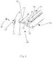
- the ejector assembly comprises an ejector 10 with a shape of "L" , being provided to rotate around an axis; a lock element 20, being provided to move along a direction substantially perpendicular to a plan of the rotation of the ejector 10; wherein the ejector 10 includes a cut-out portion 12 (e.g. a groove), the lock element 12 includes an end portion 21, and the end portion 21 is provided to match with the cut-out portion 12 to prevent the ejector 10 from rotating. As shown in figure 3 , the end portion of the lock element 20 is inserted into the cut-out portion of the ejector 10 so that the ejector 10 could not be rotated.
- a cut-out portion 12 e.g. a groove
- L does not mean the accurate L, for example, it may include a shape of arc.
- a person skilled in the art may provide various amendments, all of which could be deemed to be covered by the shape of L.
- the ejector assembly is provided to assemble with a plate element 30 (e.g. a front panel); and a matching portion 31 is provided on the plate element 30, and the lock element 20 is provided to match with the matching portion 31 so as to mount the lock element 20 on the plate element 30.
- a plate element 30 e.g. a front panel
- the lock element 20 is provided to match with the matching portion 31 so as to mount the lock element 20 on the plate element 30.
- the lock element 20 matches with the matching portion 31(As shown in figure 1 ) of the plate element 30.
- the structures of the lock element 20 and the matching portion of the plate element 30 shown in figures 1-3 are only example for clarity, and do not limit the scope of the invention. Those skilled in the art may provide various amendments to the structures.
- a hole portion 22 is provided on the lock element 20, and the hole portion 22 is configured that the lock element 20 is fixed not to move by a screw 40 going through the hole portion 22.
- Those skilled in the art may provide other amendments for attaching the lock element 20 to the plate element 30 detachably.
- the lock element 20 may move freely, and the end portion of the lock element 20 is not inserted into the cut-out portion of the ejector 40, so that the ejector 10 is capable to rotate; referring to figure 3 , wherein the screw 40 is tightened, and the end portion of the lock element 20 is inserted into the cut-out portion of the ejector 40, so that the ejector 10 does not rotate.
- an axis hole 13 is provided on the ejector 10, and the axis hole 13 is configured that the ejector 10 is mounted on the plate element 30 by a shaft 50 going through the axis hole 13.
- Those skilled in the art may provide other amendments for mounting the ejector 10 on the plate element 30 rotatablely.
- the ejector assembly further comprises a first spring 61, wherein the first spring 61 is provided between the lock element 20 and the plate element 30, and the first spring 61 is configured to provide a force on the lock element 20 along a direction substantially perpendicular to the plan of the rotation of the ejector 10.
- first spring 61 is provided between the lock element 20 and the plate element 30
- first spring 61 is configured to provide a force on the lock element 20 along a direction substantially perpendicular to the plan of the rotation of the ejector 10.
- Those skilled in the art may provide other amendments for providing a resilience force between the lock element 20 and the plate element 30.
- the ejector assembly further comprises a second spring 60, wherein the second spring 60 is provided between the ejector 10 and the plate element 30, and the second spring 60 is configured to provide a force on the ejector 10 along a direction of the ejector 10 rotation.
- the second spring 60 is provided between the ejector 10 and the plate element 30, and the second spring 60 is configured to provide a force on the ejector 10 along a direction of the ejector 10 rotation.
- Those skilled in the art may provide other amendments for providing a resilience force between the ejector 10 and the plate element 30.
- a positioning portion 14 is provided on the ejector 10, and a positioning mated portion 32 is provided on the plate element 30, and the positioning portion 14 and the positioning mated portion 32 are configured that the positioning portion 14 is matched with the positioning mated portion 32 during the ejector 10 is mounting on the plate element 30
- the positioning portion is a depression or embossment
- the positioning mated portion is a embossment or depression corresponding to the positioning portion.
- the ejector10 when the lock element 20 is fixed by the screw 40, the ejector10 is embedded in the plate element 30.
- the ejector 10 ejects from the plate element 30 by the force.
- the ejector 10 when the lock element 20 is fixed by the screw 40, the ejector 10 is embedded in the plate element 30. Therefore, when the screw 40 is tightened, it is difficult to operate the ejector by user so that a misoperation is avoided again.
- the ejector assembly in one aspect, provides that the end portion of the lock element is inserted into the cut-out portion of the ejector, so that the ejector could not be rotated, and thus the misoperation is avoided and the apparatus is protected.
- the lock element when the lock element is fixed by the screw, the ejector is embedded in the plate element and thus no enough room for hand or some tools. Therefore, when the screw is tightened, it is difficult to operate the ejector by user so that a misoperation is avoided again.
- the above two aspects provide a protection for the apparatus.
- the solutions of the above aspects may be applied singly, and may be combined.
- an electronic module 70 e.g. a line card
- an electrical apparatus 80 includes one or more electronic modules 70, wherein said one or more electronic modules 70 are equipped with the ejector assembly of the present invention.
Landscapes
- Engineering & Computer Science (AREA)
- Microelectronics & Electronic Packaging (AREA)
- Coupling Device And Connection With Printed Circuit (AREA)
- Details Of Connecting Devices For Male And Female Coupling (AREA)
- Mounting Of Printed Circuit Boards And The Like (AREA)
Claims (8)
- Auswerferanordnung für eine Montagebefestigung einer elektrischen Vorrichtung, umfassend:einen Auswerfer (10) mit einer Form eines "L", der bereitgestellt ist, um eine Achse zu rotieren;ein Sperrelement (20), das bereitgestellt ist, sich entlang einer Richtung im Wesentlichen senkrecht zu einer Rotationsebene des Auswerfers (10) zu bewegen, wobei der Auswerfer (10) einen Ausschnittabschnitt (12) enthält, das Sperrelement (20) einen Endabschnitt (21) enthält und der Endabschnitt (21) bereitgestellt ist, mit dem Ausschnittabschnitt (12) übereinzustimmen, wobei der Endpunkt in den Ausschnittabschnitt einfügbar ist, um ein Rotieren des Auswerfers (10) zu verhindern;dadurch gekennzeichnet, dass ein Lochabschnitt (22) auf dem Sperrelement (20) bereitgestellt ist, wobei der Lochabschnitt (22) so konfiguriert ist, dass das Sperrelement (20) durch eine Schraube (40), die durch den Lochabschnitt (22) geht, fixierbar ist, eine erste Feder (60), die zwischen dem Auswerfer (10) und dem Plattenelement (30) bereitgestellt ist, wobei die erste Feder (60) konfiguriert ist, eine Kraft auf dem Auswerfer (10) entlang einer Rotationsrichtung des Auswerfers (10) bereitzustellen, sodass es, wenn die Schraube (40) gelöst ist, möglich ist, das Sperrelement (20) frei zu bewegen, sodass der Endabschnitt (21) des Sperrelements (20) nicht in den Ausschnittabschnitt des Auswerfers (40) eingefügt ist, wobei der Auswerfer (10) imstande ist, so zu rotieren, dass der Auswerfer (10) durch die Kraft der Feder (60) vom Plattenelement (30) ausgeworfen wird.
- Auswerferanordnung nach Anspruch 1, wobei die Auswerferanordnung bereitgestellt ist, mit einem Plattenelement (30) zusammengefügt zu werden; und
ein Übereinstimmungsabschnitt (31) auf dem Plattenelement (30) bereitgestellt ist und das Sperrelement (20) bereitgestellt ist, mit dem Übereinstimmungsabschnitt (31) übereinzustimmen, um das Sperrelement (20) auf dem Plattenelement (30) zu montieren. - Auswerferanordnung nach Anspruch 2, wobei
ein Achsenloch (13) auf dem Auswerfer (10) bereitgestellt ist und das Achsenloch (13) konfiguriert ist, dass der Auswerfer (10) auf dem Plattenelement (30) durch eine Welle (50), die durch das Achsenloch (13) geht, montiert ist. - Auswerferanordnung nach Anspruch 2, ferner umfassend eine zweite Feder (61), wobei
die zweite Feder (61) zwischen dem Sperrelement (20) und dem Plattenelement (30) bereitgestellt ist und die zweite Feder (61) konfiguriert ist, eine Kraft auf dem Sperrelement (20) entlang einer Richtung im Wesentlichen senkrecht zur Rotationsebene des Auswerfers (10) bereitzustellen. - Auswerferanordnung nach Anspruch 2, wobei
ein Positionierungsabschnitt (14) auf dem Auswerfer (10) bereitgestellt ist und ein positionsgepaarter Abschnitt (32) auf dem Plattenelement (30) bereitgestellt ist und der Positionierungsabschnitt (14) und der positionsgepaarte Abschnitt (32) konfiguriert sind, dass der Positionierungsabschnitt (14) mit dem positionsgepaarten Abschnitt (32), während der Auswerfer (10) auf dem Plattenelement (30) montiert ist, übereinstimmt. - Auswerferanordnung nach Anspruch 1, wobei
wenn das Sperrelement (20) durch die Schraube (40) fixiert ist, der Auswerfer (10) in das Plattenelement (30) eingebettet ist. - Elektronisches Modul, das mit der Auswerferanordnung nach einem der Ansprüche von 1 bis 6 ausgestattet ist.
- Elektronische Vorrichtung, enthaltend ein oder mehrere elektronische Module, wobei das eine oder die mehreren elektronischen Module mit der Auswerferanordnung nach einem der Ansprüche von 1 bis 7 ausgestattet sind.
Applications Claiming Priority (1)
| Application Number | Priority Date | Filing Date | Title |
|---|---|---|---|
| PCT/CN2012/074649 WO2013159290A1 (en) | 2012-04-25 | 2012-04-25 | An ejector assembly |
Publications (3)
| Publication Number | Publication Date |
|---|---|
| EP2749159A1 EP2749159A1 (de) | 2014-07-02 |
| EP2749159A4 EP2749159A4 (de) | 2016-03-30 |
| EP2749159B1 true EP2749159B1 (de) | 2018-03-14 |
Family
ID=49482121
Family Applications (1)
| Application Number | Title | Priority Date | Filing Date |
|---|---|---|---|
| EP12875460.3A Not-in-force EP2749159B1 (de) | 2012-04-25 | 2012-04-25 | Auswerferanordnung |
Country Status (3)
| Country | Link |
|---|---|
| US (1) | US20150016877A1 (de) |
| EP (1) | EP2749159B1 (de) |
| WO (1) | WO2013159290A1 (de) |
Family Cites Families (26)
| Publication number | Priority date | Publication date | Assignee | Title |
|---|---|---|---|---|
| US4564250A (en) * | 1984-06-22 | 1986-01-14 | Siemens Aktiengesellschaft | Ejection and grounding system for rack-mounted plug-in modules |
| JPS6196229A (ja) | 1984-10-16 | 1986-05-14 | Nissan Motor Co Ltd | 液体封入式防振体 |
| US4648009A (en) * | 1986-04-09 | 1987-03-03 | Northern Telecom Limited | Articulated latch for use with a printed circuit board |
| US5669512A (en) * | 1995-01-05 | 1997-09-23 | Hewlett-Packard Co. | Inject-eject system for rack mounted plug-in modules |
| US5793614A (en) * | 1996-09-03 | 1998-08-11 | Tektronix, Inc. | Injector/ejector for electronic module housing |
| US6067225A (en) * | 1997-08-04 | 2000-05-23 | Sun Microsystems, Inc. | Disk drive bracket |
| US6147872A (en) * | 1999-02-08 | 2000-11-14 | Excel Switching Corporation | Injector/ejector machanism for printed circuit cards |
| US6354164B1 (en) * | 2000-04-04 | 2002-03-12 | Compaq Computer Corporation | Lever system utilizing rack and pinion gear |
| TW484047B (en) * | 2000-12-13 | 2002-04-21 | Acer Inc | Computer module carrier |
| US6561826B2 (en) * | 2001-06-08 | 2003-05-13 | Tellabs Operations, Inc. | Circuit board having an emission reducing ejector |
| EP1335644B2 (de) * | 2002-02-07 | 2010-03-03 | Schroff GmbH | Vorrichtung zum Einstecken und Herausziehen einer Steckbaugruppe |
| US20030161118A1 (en) * | 2002-02-28 | 2003-08-28 | Netezza Corporation | Front panel serving as extraction lever for circuit sled mount |
| US6671184B1 (en) * | 2002-07-12 | 2003-12-30 | International Business Machines Corporation | Latching and locking handles |
| US7397674B2 (en) * | 2003-06-09 | 2008-07-08 | Southco, Inc. | Compact PCI ejector latch |
| DE50303700D1 (de) * | 2003-07-18 | 2006-07-20 | Schroff Gmbh | Ein -und Ausziehvorrichtung einer Steckbaugruppe in bzw. aus einem Baugruppenträger |
| US6955550B2 (en) * | 2003-12-17 | 2005-10-18 | Southco, Inc. | Ejector latch with double catch |
| TWI280839B (en) * | 2004-06-21 | 2007-05-01 | Southco | Ejector lever assembly |
| US20060028804A1 (en) * | 2004-08-04 | 2006-02-09 | Fujitsu Limited | Ejector, unit and electronic apparatus having the same |
| US7292457B2 (en) * | 2005-03-31 | 2007-11-06 | Intel Corporation | Folding latching mechanism |
| US7442059B2 (en) * | 2005-11-11 | 2008-10-28 | Elma Eletronic Ag | Apparatus and method for the insertion and withdrawal of plug-in modules |
| EP1786252B1 (de) * | 2005-11-11 | 2012-06-20 | ELMA Electronic AG | Vorrichtung und Verfahren zum Einstecken und Ausziehen von Steckbaugruppen |
| US20090086456A1 (en) * | 2007-09-27 | 2009-04-02 | Sun Microsystems, Inc. | Tool-less blade ejector latch with integrated spring |
| TWI354527B (en) * | 2008-05-30 | 2011-12-11 | Asustek Comp Inc | Fixing component and case having the fixing compon |
| CN201557351U (zh) * | 2009-11-24 | 2010-08-18 | 英业达股份有限公司 | 具有固锁与释放机构的装置及其容置模块 |
| TWM414803U (en) * | 2011-03-11 | 2011-10-21 | Hon Hai Prec Ind Co Ltd | Ejector assembly |
| FR2977282B1 (fr) * | 2011-06-29 | 2014-04-11 | Airbus Operations Sas | Dispositif de verrouillage de cartes electroniques dans des equipements embarques |
-
2012
- 2012-04-25 WO PCT/CN2012/074649 patent/WO2013159290A1/en not_active Ceased
- 2012-04-25 US US14/382,275 patent/US20150016877A1/en not_active Abandoned
- 2012-04-25 EP EP12875460.3A patent/EP2749159B1/de not_active Not-in-force
Non-Patent Citations (1)
| Title |
|---|
| None * |
Also Published As
| Publication number | Publication date |
|---|---|
| EP2749159A4 (de) | 2016-03-30 |
| WO2013159290A1 (en) | 2013-10-31 |
| US20150016877A1 (en) | 2015-01-15 |
| EP2749159A1 (de) | 2014-07-02 |
Similar Documents
| Publication | Publication Date | Title |
|---|---|---|
| US9374924B2 (en) | DIN rail mounted enclosure assembly and method of use | |
| US9766667B1 (en) | Computer card ejector with latch | |
| US8570738B2 (en) | Handle structure of electronic device enclosure | |
| US20130127311A1 (en) | Electronic device enclosure with bracket for fan module | |
| EP3270669B1 (de) | Klammervorrichtung | |
| US20030227740A1 (en) | Top cover of a computer system housing | |
| CN119322554B (zh) | 一种服务器和服务器组装方法 | |
| US8054619B1 (en) | Partial-slot card guide installation tool | |
| US20130168530A1 (en) | Mounting apparatus for fan module | |
| JP3417378B2 (ja) | コネクタ装置、そのコネクタ装置を用いたインターフェイスモジュール、及びコネクタ芯数変換アダプタ | |
| EP2749159B1 (de) | Auswerferanordnung | |
| WO2007100349A1 (en) | Drive carrier | |
| US9743550B2 (en) | Rail for mounting a rack-mountable component | |
| US8657622B1 (en) | Electrical connector assembly | |
| US20120327578A1 (en) | Mounting apparatus for pci card | |
| US7054160B2 (en) | Apparatus for attaching and detaching circuit boards | |
| US7918686B1 (en) | Server with improved connecting port | |
| EP3136694B1 (de) | Gehäusemontagemechanismus für tragbare elektronische vorrichtung | |
| US20050239310A1 (en) | Floating connectors | |
| US6724621B1 (en) | Portable hard disk drive cartridge having adaptable interface | |
| CN202333321U (zh) | 一种用于连接器的防错插结构 | |
| CN102509955A (zh) | 一种用于连接器的防错插结构 | |
| CN215293019U (zh) | 把手组件及便捷式装拆结构 | |
| EP2672794B1 (de) | Einspritzmechanismus für Module und Verwendungsverfahren dafür | |
| CN105226449A (zh) | 用于连接器组件的导引销 |
Legal Events
| Date | Code | Title | Description |
|---|---|---|---|
| PUAI | Public reference made under article 153(3) epc to a published international application that has entered the european phase |
Free format text: ORIGINAL CODE: 0009012 |
|
| 17P | Request for examination filed |
Effective date: 20140326 |
|
| AK | Designated contracting states |
Kind code of ref document: A1 Designated state(s): AL AT BE BG CH CY CZ DE DK EE ES FI FR GB GR HR HU IE IS IT LI LT LU LV MC MK MT NL NO PL PT RO RS SE SI SK SM TR |
|
| RAP1 | Party data changed (applicant data changed or rights of an application transferred) |
Owner name: TELEFONAKTIEBOLAGET L M ERICSSON (PUBL) |
|
| DAX | Request for extension of the european patent (deleted) | ||
| RA4 | Supplementary search report drawn up and despatched (corrected) |
Effective date: 20160229 |
|
| RIC1 | Information provided on ipc code assigned before grant |
Ipc: H05K 7/00 20060101AFI20160223BHEP Ipc: H05K 7/14 20060101ALI20160223BHEP Ipc: H05K 5/02 20060101ALI20160223BHEP |
|
| RIC1 | Information provided on ipc code assigned before grant |
Ipc: H05K 7/14 20060101ALI20170711BHEP Ipc: H05K 5/02 20060101ALI20170711BHEP Ipc: H05K 7/00 20060101AFI20170711BHEP |
|
| GRAP | Despatch of communication of intention to grant a patent |
Free format text: ORIGINAL CODE: EPIDOSNIGR1 |
|
| STAA | Information on the status of an ep patent application or granted ep patent |
Free format text: STATUS: GRANT OF PATENT IS INTENDED |
|
| INTG | Intention to grant announced |
Effective date: 20171009 |
|
| GRAS | Grant fee paid |
Free format text: ORIGINAL CODE: EPIDOSNIGR3 |
|
| GRAA | (expected) grant |
Free format text: ORIGINAL CODE: 0009210 |
|
| STAA | Information on the status of an ep patent application or granted ep patent |
Free format text: STATUS: THE PATENT HAS BEEN GRANTED |
|
| AK | Designated contracting states |
Kind code of ref document: B1 Designated state(s): AL AT BE BG CH CY CZ DE DK EE ES FI FR GB GR HR HU IE IS IT LI LT LU LV MC MK MT NL NO PL PT RO RS SE SI SK SM TR |
|
| REG | Reference to a national code |
Ref country code: GB Ref legal event code: FG4D |
|
| REG | Reference to a national code |
Ref country code: CH Ref legal event code: EP Ref country code: AT Ref legal event code: REF Ref document number: 980056 Country of ref document: AT Kind code of ref document: T Effective date: 20180315 |
|
| REG | Reference to a national code |
Ref country code: IE Ref legal event code: FG4D |
|
| REG | Reference to a national code |
Ref country code: DE Ref legal event code: R096 Ref document number: 602012044074 Country of ref document: DE |
|
| REG | Reference to a national code |
Ref country code: NL Ref legal event code: FP |
|
| REG | Reference to a national code |
Ref country code: LT Ref legal event code: MG4D |
|
| PG25 | Lapsed in a contracting state [announced via postgrant information from national office to epo] |
Ref country code: LT Free format text: LAPSE BECAUSE OF FAILURE TO SUBMIT A TRANSLATION OF THE DESCRIPTION OR TO PAY THE FEE WITHIN THE PRESCRIBED TIME-LIMIT Effective date: 20180314 Ref country code: CY Free format text: LAPSE BECAUSE OF FAILURE TO SUBMIT A TRANSLATION OF THE DESCRIPTION OR TO PAY THE FEE WITHIN THE PRESCRIBED TIME-LIMIT Effective date: 20180314 Ref country code: HR Free format text: LAPSE BECAUSE OF FAILURE TO SUBMIT A TRANSLATION OF THE DESCRIPTION OR TO PAY THE FEE WITHIN THE PRESCRIBED TIME-LIMIT Effective date: 20180314 Ref country code: FI Free format text: LAPSE BECAUSE OF FAILURE TO SUBMIT A TRANSLATION OF THE DESCRIPTION OR TO PAY THE FEE WITHIN THE PRESCRIBED TIME-LIMIT Effective date: 20180314 Ref country code: NO Free format text: LAPSE BECAUSE OF FAILURE TO SUBMIT A TRANSLATION OF THE DESCRIPTION OR TO PAY THE FEE WITHIN THE PRESCRIBED TIME-LIMIT Effective date: 20180614 Ref country code: ES Free format text: LAPSE BECAUSE OF FAILURE TO SUBMIT A TRANSLATION OF THE DESCRIPTION OR TO PAY THE FEE WITHIN THE PRESCRIBED TIME-LIMIT Effective date: 20180314 |
|
| REG | Reference to a national code |
Ref country code: AT Ref legal event code: MK05 Ref document number: 980056 Country of ref document: AT Kind code of ref document: T Effective date: 20180314 |
|
| PG25 | Lapsed in a contracting state [announced via postgrant information from national office to epo] |
Ref country code: RS Free format text: LAPSE BECAUSE OF FAILURE TO SUBMIT A TRANSLATION OF THE DESCRIPTION OR TO PAY THE FEE WITHIN THE PRESCRIBED TIME-LIMIT Effective date: 20180314 Ref country code: GR Free format text: LAPSE BECAUSE OF FAILURE TO SUBMIT A TRANSLATION OF THE DESCRIPTION OR TO PAY THE FEE WITHIN THE PRESCRIBED TIME-LIMIT Effective date: 20180615 Ref country code: LV Free format text: LAPSE BECAUSE OF FAILURE TO SUBMIT A TRANSLATION OF THE DESCRIPTION OR TO PAY THE FEE WITHIN THE PRESCRIBED TIME-LIMIT Effective date: 20180314 Ref country code: SE Free format text: LAPSE BECAUSE OF FAILURE TO SUBMIT A TRANSLATION OF THE DESCRIPTION OR TO PAY THE FEE WITHIN THE PRESCRIBED TIME-LIMIT Effective date: 20180314 Ref country code: BG Free format text: LAPSE BECAUSE OF FAILURE TO SUBMIT A TRANSLATION OF THE DESCRIPTION OR TO PAY THE FEE WITHIN THE PRESCRIBED TIME-LIMIT Effective date: 20180614 |
|
| PG25 | Lapsed in a contracting state [announced via postgrant information from national office to epo] |
Ref country code: AL Free format text: LAPSE BECAUSE OF FAILURE TO SUBMIT A TRANSLATION OF THE DESCRIPTION OR TO PAY THE FEE WITHIN THE PRESCRIBED TIME-LIMIT Effective date: 20180314 Ref country code: EE Free format text: LAPSE BECAUSE OF FAILURE TO SUBMIT A TRANSLATION OF THE DESCRIPTION OR TO PAY THE FEE WITHIN THE PRESCRIBED TIME-LIMIT Effective date: 20180314 Ref country code: IT Free format text: LAPSE BECAUSE OF FAILURE TO SUBMIT A TRANSLATION OF THE DESCRIPTION OR TO PAY THE FEE WITHIN THE PRESCRIBED TIME-LIMIT Effective date: 20180314 Ref country code: RO Free format text: LAPSE BECAUSE OF FAILURE TO SUBMIT A TRANSLATION OF THE DESCRIPTION OR TO PAY THE FEE WITHIN THE PRESCRIBED TIME-LIMIT Effective date: 20180314 Ref country code: PL Free format text: LAPSE BECAUSE OF FAILURE TO SUBMIT A TRANSLATION OF THE DESCRIPTION OR TO PAY THE FEE WITHIN THE PRESCRIBED TIME-LIMIT Effective date: 20180314 |
|
| PG25 | Lapsed in a contracting state [announced via postgrant information from national office to epo] |
Ref country code: SK Free format text: LAPSE BECAUSE OF FAILURE TO SUBMIT A TRANSLATION OF THE DESCRIPTION OR TO PAY THE FEE WITHIN THE PRESCRIBED TIME-LIMIT Effective date: 20180314 Ref country code: CZ Free format text: LAPSE BECAUSE OF FAILURE TO SUBMIT A TRANSLATION OF THE DESCRIPTION OR TO PAY THE FEE WITHIN THE PRESCRIBED TIME-LIMIT Effective date: 20180314 Ref country code: AT Free format text: LAPSE BECAUSE OF FAILURE TO SUBMIT A TRANSLATION OF THE DESCRIPTION OR TO PAY THE FEE WITHIN THE PRESCRIBED TIME-LIMIT Effective date: 20180314 Ref country code: SM Free format text: LAPSE BECAUSE OF FAILURE TO SUBMIT A TRANSLATION OF THE DESCRIPTION OR TO PAY THE FEE WITHIN THE PRESCRIBED TIME-LIMIT Effective date: 20180314 |
|
| REG | Reference to a national code |
Ref country code: CH Ref legal event code: PL |
|
| REG | Reference to a national code |
Ref country code: DE Ref legal event code: R097 Ref document number: 602012044074 Country of ref document: DE |
|
| REG | Reference to a national code |
Ref country code: BE Ref legal event code: MM Effective date: 20180430 |
|
| PG25 | Lapsed in a contracting state [announced via postgrant information from national office to epo] |
Ref country code: PT Free format text: LAPSE BECAUSE OF FAILURE TO SUBMIT A TRANSLATION OF THE DESCRIPTION OR TO PAY THE FEE WITHIN THE PRESCRIBED TIME-LIMIT Effective date: 20180716 |
|
| PLBE | No opposition filed within time limit |
Free format text: ORIGINAL CODE: 0009261 |
|
| STAA | Information on the status of an ep patent application or granted ep patent |
Free format text: STATUS: NO OPPOSITION FILED WITHIN TIME LIMIT |
|
| REG | Reference to a national code |
Ref country code: IE Ref legal event code: MM4A |
|
| PG25 | Lapsed in a contracting state [announced via postgrant information from national office to epo] |
Ref country code: LU Free format text: LAPSE BECAUSE OF NON-PAYMENT OF DUE FEES Effective date: 20180425 Ref country code: DK Free format text: LAPSE BECAUSE OF FAILURE TO SUBMIT A TRANSLATION OF THE DESCRIPTION OR TO PAY THE FEE WITHIN THE PRESCRIBED TIME-LIMIT Effective date: 20180314 Ref country code: MC Free format text: LAPSE BECAUSE OF FAILURE TO SUBMIT A TRANSLATION OF THE DESCRIPTION OR TO PAY THE FEE WITHIN THE PRESCRIBED TIME-LIMIT Effective date: 20180314 |
|
| 26N | No opposition filed |
Effective date: 20181217 |
|
| PG25 | Lapsed in a contracting state [announced via postgrant information from national office to epo] |
Ref country code: SI Free format text: LAPSE BECAUSE OF FAILURE TO SUBMIT A TRANSLATION OF THE DESCRIPTION OR TO PAY THE FEE WITHIN THE PRESCRIBED TIME-LIMIT Effective date: 20180314 Ref country code: CH Free format text: LAPSE BECAUSE OF NON-PAYMENT OF DUE FEES Effective date: 20180430 Ref country code: LI Free format text: LAPSE BECAUSE OF NON-PAYMENT OF DUE FEES Effective date: 20180430 Ref country code: BE Free format text: LAPSE BECAUSE OF NON-PAYMENT OF DUE FEES Effective date: 20180430 |
|
| PG25 | Lapsed in a contracting state [announced via postgrant information from national office to epo] |
Ref country code: IE Free format text: LAPSE BECAUSE OF NON-PAYMENT OF DUE FEES Effective date: 20180425 Ref country code: FR Free format text: LAPSE BECAUSE OF NON-PAYMENT OF DUE FEES Effective date: 20180514 |
|
| PG25 | Lapsed in a contracting state [announced via postgrant information from national office to epo] |
Ref country code: MT Free format text: LAPSE BECAUSE OF NON-PAYMENT OF DUE FEES Effective date: 20180425 |
|
| PG25 | Lapsed in a contracting state [announced via postgrant information from national office to epo] |
Ref country code: TR Free format text: LAPSE BECAUSE OF FAILURE TO SUBMIT A TRANSLATION OF THE DESCRIPTION OR TO PAY THE FEE WITHIN THE PRESCRIBED TIME-LIMIT Effective date: 20180314 |
|
| PG25 | Lapsed in a contracting state [announced via postgrant information from national office to epo] |
Ref country code: HU Free format text: LAPSE BECAUSE OF FAILURE TO SUBMIT A TRANSLATION OF THE DESCRIPTION OR TO PAY THE FEE WITHIN THE PRESCRIBED TIME-LIMIT; INVALID AB INITIO Effective date: 20120425 |
|
| PG25 | Lapsed in a contracting state [announced via postgrant information from national office to epo] |
Ref country code: MK Free format text: LAPSE BECAUSE OF NON-PAYMENT OF DUE FEES Effective date: 20180314 |
|
| PG25 | Lapsed in a contracting state [announced via postgrant information from national office to epo] |
Ref country code: IS Free format text: LAPSE BECAUSE OF FAILURE TO SUBMIT A TRANSLATION OF THE DESCRIPTION OR TO PAY THE FEE WITHIN THE PRESCRIBED TIME-LIMIT Effective date: 20180714 |
|
| PGFP | Annual fee paid to national office [announced via postgrant information from national office to epo] |
Ref country code: NL Payment date: 20220426 Year of fee payment: 11 |
|
| PGFP | Annual fee paid to national office [announced via postgrant information from national office to epo] |
Ref country code: GB Payment date: 20220427 Year of fee payment: 11 Ref country code: DE Payment date: 20220427 Year of fee payment: 11 |
|
| REG | Reference to a national code |
Ref country code: DE Ref legal event code: R119 Ref document number: 602012044074 Country of ref document: DE |
|
| REG | Reference to a national code |
Ref country code: NL Ref legal event code: MM Effective date: 20230501 |
|
| GBPC | Gb: european patent ceased through non-payment of renewal fee |
Effective date: 20230425 |
|
| PG25 | Lapsed in a contracting state [announced via postgrant information from national office to epo] |
Ref country code: GB Free format text: LAPSE BECAUSE OF NON-PAYMENT OF DUE FEES Effective date: 20230425 |
|
| PG25 | Lapsed in a contracting state [announced via postgrant information from national office to epo] |
Ref country code: NL Free format text: LAPSE BECAUSE OF NON-PAYMENT OF DUE FEES Effective date: 20230501 Ref country code: GB Free format text: LAPSE BECAUSE OF NON-PAYMENT OF DUE FEES Effective date: 20230425 Ref country code: DE Free format text: LAPSE BECAUSE OF NON-PAYMENT OF DUE FEES Effective date: 20231103 |