EP2749207B1 - Procédé de simulation de port de lunettes, programme, dispositif, système de commande de verres de lunettes et procédé de fabrication de verres de lunettes - Google Patents
Procédé de simulation de port de lunettes, programme, dispositif, système de commande de verres de lunettes et procédé de fabrication de verres de lunettes Download PDFInfo
- Publication number
- EP2749207B1 EP2749207B1 EP12826151.8A EP12826151A EP2749207B1 EP 2749207 B1 EP2749207 B1 EP 2749207B1 EP 12826151 A EP12826151 A EP 12826151A EP 2749207 B1 EP2749207 B1 EP 2749207B1
- Authority
- EP
- European Patent Office
- Prior art keywords
- eyeglass lens
- eye
- eyeglass
- pair
- eyeglasses
- Prior art date
- Legal status (The legal status is an assumption and is not a legal conclusion. Google has not performed a legal analysis and makes no representation as to the accuracy of the status listed.)
- Active
Links
Images



Classifications
-
- A—HUMAN NECESSITIES
- A61—MEDICAL OR VETERINARY SCIENCE; HYGIENE
- A61B—DIAGNOSIS; SURGERY; IDENTIFICATION
- A61B3/00—Apparatus for testing the eyes; Instruments for examining the eyes
- A61B3/02—Subjective types, i.e. testing apparatus requiring the active assistance of the patient
- A61B3/09—Subjective types, i.e. testing apparatus requiring the active assistance of the patient for testing accommodation
-
- A—HUMAN NECESSITIES
- A61—MEDICAL OR VETERINARY SCIENCE; HYGIENE
- A61B—DIAGNOSIS; SURGERY; IDENTIFICATION
- A61B3/00—Apparatus for testing the eyes; Instruments for examining the eyes
- A61B3/0016—Operational features thereof
- A61B3/0025—Operational features thereof characterised by electronic signal processing, e.g. eye models
-
- A—HUMAN NECESSITIES
- A61—MEDICAL OR VETERINARY SCIENCE; HYGIENE
- A61B—DIAGNOSIS; SURGERY; IDENTIFICATION
- A61B3/00—Apparatus for testing the eyes; Instruments for examining the eyes
- A61B3/0016—Operational features thereof
- A61B3/0041—Operational features thereof characterised by display arrangements
- A61B3/0058—Operational features thereof characterised by display arrangements for multiple images
-
- G—PHYSICS
- G02—OPTICS
- G02C—SPECTACLES; SUNGLASSES OR GOGGLES INSOFAR AS THEY HAVE THE SAME FEATURES AS SPECTACLES; CONTACT LENSES
- G02C7/00—Optical parts
- G02C7/02—Lenses; Lens systems ; Methods of designing lenses
- G02C7/024—Methods of designing ophthalmic lenses
- G02C7/028—Special mathematical design techniques
Definitions
- the present invention relates to an eyeglasses-wearing simulation method, eyeglasses-wearing simulation program, an eyeglasses-wearing simulation device, an eyeglass lens-ordering system and an eyeglass lens manufacturing method for simulating how the outside is viewed when a pair of left and right eyeglass lenses are placed in front of left and right eyes.
- an eye examination is conducted for a patient, and the type of eyeglass lens is selected based on a prescription obtained by eye examination.
- the types of eyeglass lens include a single-vision spherical lens, a single-vision aspherical lens, a fatigue-relieving lens, a near vision lens dedicated for near vision, a progressive power lens (distance/near vision type, intermediate/near vision type).
- a plurality of types of eyeglass lenses a plurality of types of test lenses are prepared.
- a test lens is inserted into a temporary frame and is put on a patient on a trial basis so that the prescribed power is achieved.
- Japanese Patent Publication No. 3342423 (hereafter, referred to as "patent document 1") describes an example of a specific configuration of an eyeglass-wearing simulation device.
- the eyeglass-wearing simulation device described in patent document 1 simulates the visual performance in a state where an eyeglass lens is placed in front of a single eye. To achieve the precise simulation, the simulation device of this type is able to reproduce the visual performance while considering shaking, distortion and blur caused during wearing of the eyeglass while further considering perception of a human.
- the document EP 1 158 338 A2 describes a binocular synkinetic rotation-based retinal image which is defined as an image obtained by rotating both eyeballs toward each of all object points in a visual field, then, uniting images projected on the foveae of right and left eyes and connecting the united images.
- the midpoint of binocular rotation is placed at a specific position, and as the original image, the image of objects in within a specific pyramidal visual field having the apex at the midpoint is created.
- an image derived by observing the original image through spectacle lenses and having distortions within a united binocular space is created in accordance with the ray tracing method.
- the object of the present invention is to provide an eyeglasses-wearing simulation method, an eyeglasses-wearing simulation program, an eyeglasses-wearing simulation device, an eyeglass lens-ordering system and an eyeglass manufacturing method suitable for simulating how the outside is viewed in binocular vision when a wearer wears eyeglasses.
- an eyeglasses-wearing simulation method for simulating how an outside is viewed when a pair of left and right eyeglass lenses are placed in front of left and right eyes according to claim 1.
- the patient is given the eyeglass lens-wearing simulation which reflects more accurately how the outside is viewed when the eyeglass lenses are worn, and is able to achieve the stereoscopic viewing for the parallax images in a feeling close to the reality.
- An eyeglasses-wearing simulation program is a program for causing a computer to execute the above described eyeglasses-wearing simulation method.
- an eyeglasses-wearing simulation device for simulating how an outside is viewed when a pair of left and right eyeglass lenses is placed in front of left and right according to claim 3.
- an eyeglass lens-ordering system for ordering a pair of eyeglass lenses using an eyeglasses-wearing simulation device for simulating how an outside is viewed when the pair of left and right eyeglass lenses is placed in front of left and right eyes, comprising: the above described eyeglasses-wearing simulation device; and an order data transmission means for transmitting, as ordering data, one of the prescription information used by the image creation means of the eyeglasses-wearing simulation device and eyeglass lens pair data designed based on the prescription data, to a predetermined ordering destination.
- an eyeglass lens manufacturing method according to claim 5.
- an eyeglasses-wearing simulation method an eyeglasses-wearing simulation program, an eyeglasses-wearing simulation device, an eyeglass lens-ordering system and an eyeglass manufacturing method suitable for simulating how the outside is viewed in binocular vision when a wearer wears eyeglasses are provided.
- Fig. 1 generally illustrates an eyeglass lens-ordering system 10 according to the embodiment.
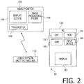
- Fig. 2 is a block diagram illustrating a configuration of the eyeglass lens-ordering system 10.
- the eyeglass lens-ordering system 10 which is installed, for example, in an eyeglass store is configured to simulate how the outside is viewed when a pair of left and right eyeglass lenses is placed in front of left and right eyes.
- the eyeglass lens-ordering system 10 includes a video monitor 102, and a store computer 130 connected to the video monitor 102.
- the eyeglass lens-ordering system 10 has the video monitor 102.
- the video monitor 102 is a video monitor (e.g., a liquid crystal display panel TV or a plasma display panel TV) which supports displaying of a three-dimensional image and enables a patent 2 to perform stereoscopic viewing by utilizing binocular parallax.
- the video monitor 102 uses a flame sequential scheme.
- An image processing engine 104 of the video monitor 102 generates parallax images for the left and right eyes by processing image data inputted from the store computer 130, and alternately displays the parallax images on a display screen 106 at a high speed.
- the patient 2 wears a liquid crystal shutter eyeglass 112 and stands at a reference point, and views the display screen 106 with the head (chin) of the patient 2 being fixed.
- a synchronization signal is transmitted from a transmitter 108 mounted on the video monitor 102.
- the liquid crystal shutter eyeglass 112 controls orientation of liquid crystal in synchronization with the parallax images displayed on the display screen 106 to alternately block the left and right fields of vision.
- the right eye of the patient 2 views only a right eye virtual image and a left eye of the patient 2 views only a left eye virtual image.
- the patient 2 perceives, as a three-dimensional object, the parallax images which are displayed on the display screen 106 of the video monitor 103 and are converged at non-corresponding points within Panum's fusional area on retinas.
- a displaying format of a three-dimensional image on the video monitor 102 used in the eyeglass lens-ordering system 10 is not limited to the frame sequential scheme.
- an anaglyph scheme where a person stereoscopically views parallax images through red and blue color filter eyeglasses or a polarization scheme where a person stereoscopically views, through polarized glasses, parallax images of which polarized conditions are orthogonal to each other may be employed.
- a so-called naked eye scheme such as a parallax barrier or a lenticular lens, may be employed.
- observation distance od the distance between the display screen 106 and the eyes of the patient 2 is fixed.
- the observation distance od may be changed for enlarging or reducing the visual field with respect to the virtual mage.
- the video monitor 102 is installed on a seating 122.
- the seating 122 is configured to be slidable on rails 124. By sliding the seating 122, the observation distance od changes.
- the changed observation distance od may be directly inputted to the store computer 130 by an operator, or the slid distance of the seating 122 may be detected by a sensor (not shown) and the store computer 130 may employ the detected distance as data.
- the parallax of the virtual images of the left and right eyes need to be changed depending on the observation distance od. That is, it is necessary to produce again the virtual images of the left and right eyes each time the observation distance od is changed.
- the store computer 130 is, for example, an ordinary PC (Personal Computer), and includes a CPU (Central Processing Unit) 132, an HDD (Hard Disk Drive) 134, a RAM (Random Access Memory), an input device 138 (keys, a mouse, a game pad and etc.) and a display 140.
- a CPU Central Processing Unit
- HDD Hard Disk Drive
- RAM Random Access Memory
- input device 138 keyboards, a mouse, a game pad and etc.
- a display 140 a display 140.
- an eyeglasses-wearing simulation program for simulating how the outside is viewed when a pair of left and right eyeglass lenses are placed in front of the left and right eyes.
- the CPU 132 starts the eyeglasses-wearing simulation program by loading the eyeglasses-wearing simulation program onto the RAM 136.
- a GUI Graphic User Interface
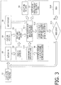
- Fig. 3 is an explanatory illustration for explaining a flow of the eyeglasses-wearing simulation by the eyeglasses-wearing simulation program.
- Eye examination is conducted for the patient 2 by an operator who is eyeglass store staff. As a result, a prescription for the patient 2 is determined.
- the prescription includes spherical power, cylindrical power, cylindrical axis direction, prismatic power, prism base setting, an addition power and distance portion PD (Pupillary Distance) and near portion PD.
- the operator inputs various prescription data by operating the GUI. Alternatively, data of the various prescription data may be automatically created based on the results of the eye examination.
- the selectable eyeglass lenses include, for example, a single-vision spherical lens, a single-vision aspherical lens, a fatigue-relieving lens, a near vision lens dedicated for near vision, a progressive power lens (distance/near vision type, intermediate/near vision type).
- the eyeglasses-wearing simulation program creates surface shape data so that the prescribed power is achieved by the eyeglass lens of the type selected in step S2 in Fig. 3 .
- the surface shape data may be created, for example, through a known design program.
- a plurality of types of surface shape data, each of which is uniquely defined by the prescribed power and the type of eyeglass lens, may be prepared in advance in the HDD 134. That is, the eyeglasses-wearing simulation program selects specific surface shape data corresponding to the selected type of eyeglass and the prescribed power, from among data which has been stored in advance, in place of creating surface shape data by the design program.
- Execution of the design program may be performed, for example, by a server of an eyeglass lens maker connected to the store computer 130 via a network.
- the specific surface shape data may be stored in the server of the eyeglass lens maker.
- the operator operates the GUI and inputs layout data corresponding to a request from the patent 2.
- the layout data includes a position of an eye point, a pantoscopic angle and a tilting angle.
- a default value is used.
- the eyeglasses-wearing simulation program creates the whole visual field light ray data.
- the whole visual field light ray data is described later.
- the operator operates the GUI and inputs shape data of the frame selected by the patient 2.
- the frame data is managed, for example, by a barcode tag, and can be obtained by reading a barcode tag adhered to the frame through use of a barcode reader.
- a default value is used.
- the operator operates the GUI and selects a desired one scene from among a plurality of three-dimensional virtual scenes prepared in advance.
- the plurality of three-dimensional virtual scenes are, for example, a scene for a distance vision where distance objects are principally arranged, a scene for a near vision for reading books or operating a mobile terminal, and a scene in an office.
- the three-dimensional virtual scene includes a left eye original image which is an image of virtual objects existing within a pyramid space of a specific visual field defined by placing a rotation center of the left eyeball at a specific position, setting a vertex at the rotation center of the left eyeball and setting a specific visual line direction (a visual line direction of the rotation center of the left eye) as an axis, and a right eye original image which is an image of virtual objects existing within a pyramid space of a specific visual field defined by placing a rotation center of the right eyeball at a position separated by the distance PD from the rotation center of the left eyeball, setting a vertex at the rotation center of the right eyeball and setting an axis extending in the same direction as the visual line direction of the rotation center of the left eye.
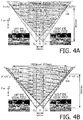
- Figs. 4A , 5A and 5B are explanatory illustrations for explaining creation of the original images.
- the depth direction perpendicular to the display screen 106 of the video monitor 102 is defined as x-axis
- the up and down direction and the left and right direction which are parallel with the display screen 106 are defined as y-axis and z-axis, respectively.
- the display screen 106 of the video monitor 102 is a rectangular area (having an aspect ratio of 16:9) surrounded by four apexes A 1 , A 2 , A 3 and A 4 , and has the size of 510mm x 287mm and the resolution of 1920pixel x 1080pixel.
- Points extending from the left and right eyeball rotation centers O L and O R in the x-axis direction and intersecting with the display screen 106 are defined as points A L and A R , respectively.
- the observation distance od is the distance OA between the middle point O of the left and right eyeball rotation centers O L and O R and the display screen center A of the video monitor 102, and is 650mm (the distance O L A L and the distance O R A R are equal to each other, and are 650mm). Therefore, the visual field becomes 43°(width) by 25° (height).
- the interval between the left and right eyeball rotation centers O L and O R is defined as 64mm.
- the eyeglasses-wearing simulation program places virtual objects in a three dimensional virtual space through use of a known computer graphics scheme.
- the virtual objects constitute the three dimensional virtual scene selected by the patient 2, and are, for example, virtual desk, chair and furniture placed in a virtual room or virtual flowerbed, tree and sign disposed on a virtual field.
- the three dimensional virtual scene is created.
- the eyeglasses-wearing simulation program places the left eyeball rotation center O L at a specific position in the three dimensional virtual space. Then, the eyeglasses-wearing simulation program sets, as the visual field, a specific pyramid space A 1 , A 2 , A 3 and A 4 defined by setting a vertex at the left eyeball rotation center O L and setting, as an axis, the left eye visual line A L O L parallel with the x-axis, and creates, as the left eye original image, an image of the virtual objects in the visual field.
- T and C are orientation parameters of the object point P L (x L , y L , z L ).
- the eyeglasses-wearing simulation program creates the right eye original image through the same manner as that described above, and calculates the object point distance between the right eye rotation center O R and each of the object points corresponding to pixels of the right eye original image (see Fig. 5B ).
- the object point distance and the visual line direction of the left eye are different from those of the right eye because the left and right eyeball rotation centers O L and O R are shifted with respect to each other in the z-axis direction. Therefore, the left and right original images, which reflect a common virtual object, have parallax.
- each original image is created by separately defining the visual filed spaces of the left and right eyes, and the object point distances to the object points corresponding to the pixels are calculated; however, to make the calculation process more efficient, a common visual field space for the left and right eyes may be defined and creation of original images for the left and right eyes and calculation of the object point distances may be performed.
- the common visual filed space for the left and right eyes can be defined by a pyramid having a vertex at the middle point O between the left and right rotation centers O L and O R (see Fig. 6A ).
- the left and right original images and the object point distances to the object points corresponding to the pixels are obtained through calculation by expressions indicated below.
- An arbitrary object point P(x, y, z) in the binocular visual field is expressed by the inverse number D of the object point distance OP, the angle ⁇ formed by the vector PO and the x-axis and the angle of direction ⁇ which are defined by the following expressions.
- the object point distance is represented by the inverse number for convenience of explanation about the spline function which is described later.
- the orientation parameters T L , C L , T R , C R of each object point of each of the left and right eyes are defined as follows based on the orientation parameters T and C in the binocular visual field.
- the image where each object point is expressed by the coordinate system of the orientation parameters T L and C L is the left eye original image.
- the image where each object point is expressed by the coordinate system of the orientation parameters T R and C R is the right eye original image.
- the inverse number D L of the object point distance O L P and the inverse number D R of the object point distance O R P are defined as follows.
- the lens use position means a position at which the visual line to the center of the visual field intersects with the eyeglass lens.
- the type of eyeglass lens selected in the step S2 in Fig. 3 is a progressive power lens.
- the eyeglasses-wearing simulation program designates, as the lens use position, an upper position on the eyeglass lens (e.g., the distance eye point).
- the eyeglasses-wearing simulation program uses, as the lens use position, a lower position on the eyeglass lens (e.g., the near eye point).
- the operator operates the GUI, and selects presence/absence of the special processing such as of the surface processing, dimmer control, dyeing and etc.
- the special processing includes dyeing processing, hard coating, anti-reflection coating, ultraviolet light cutting and dimmer control processing.
- the eyeglasses-wearing simulation program creates transmittance data by wavelengths in accordance with the special processing selected in the step S9 in Fig. 3 . By using this data, the eyeglasses-wearing simulation program changes color of the visual field image which is viewed through the eyeglass lens which has been subjected to the special processing.
- the visual field deforms due to the refractive effect by the eyeglass lens and blur occurs.
- the left eye visual field changes from A 1 O L A 4 (A 2 O L A 3 ) to A' 1 O L A' 4 (A' 2 O L A' 3 )
- the right eye visual field changes from A 1 O R A 4 (A 2 O R A 3 ) to A' 1 O R A' 4 (A' 2 O R A' 3 ).
- the stereognostic sense of the binocular vision also changes, in addition to change of the distortion and blur of the monocular vision.
- the light ray data of the whole visual field is created to precisely reflect the distortion and blur caused by the left and right eyes in the visual fields of the left and right eyes.
- the distortion in the left and right eyes when an object point P is viewed is explained.
- the eyeglass lens is placed in front of the eye to have predetermined posture and position (e.g., vertex distance between the corneal apex and the back vertex of the eyeglass lens, eye point, a pantoscopic angle and a tilting angle)
- a light ray from an arbitrary object point P reaches the eye while being refracted by the eyeglass lens.
- the object point P is viewed, from the left and right eyes, as lying on the extension line of the exit light ray Q L O L (or Q R O R ) of the eyeglass lens.
- the fact that the orientation of the exit light ray Q L O L (or (Q R O R ) is different from the original light ray PO L (or PO R ) causes the distortion of the visual line.
- the left eye attempts to capture the object point P on the optical axis by rotating toward the exit light ray Q L O L (or Q R O R ).
- the amount of accommodation of the eyeball required to cause an image of the object point P to converge on the retina is determined by wavefront power of the light ray radiated from the object point P at the back vertex spherical surface and the correction power for distance vision of the eye. For example, we assume that the correction power for distance vision of the eye is zero.
- the back vertex spherical surface means a spherical surface whose radius is the distance between the rotation center of the eye and the back vertex of the eyeglass lens and which has the center at the rotation center of the eye.
- the amounts of accommodation of the left and right eyes are determined according to the following rules A and B. Since, as a result, the same amount of accommodation is set for each of the left and right eyes, the condition where the object point is not suitably converged on the retina can be realized, and thereby the blur is reproduced more accurately in comparison with the conventional eyeglass-wearing simulation for a single eye.
- the amount of accommodation by a dominant eye of the patient 2 is defined as the amount of accommodation for the left and right eyes.
- a smaller one of the required amounts of accommodation for the left and right eyes is defined as the amount of accommodation for the left and right eyes.
- an arbitrary point P(x,y,z) in the visual field space can be specified by the distance from the rotation center O and the orientation parameters T, C or ⁇ , ⁇ .
- the distance PO is represented by the inverse number D, and, for an infinite distance, the inverse number is zero.
- the orientation parameter Y is a tangent of the vertical angle of direction, and C is a tangent of the horizontal angle of direction.
- the vertical/horizontal directions are represented by the polar coordinate, they are the angle of radius ⁇ and the polar angle of direction ⁇ .
- T and C are calculated from the coordinate of the object point; however, T and C may be calculated from the direction cosine. Rather, in general, T and C are calculated from the direction cosine.
- a unit vector PO is represented by the following expression: PO ⁇
- l i + m j + n k
- T and C are defined as follows.
- T m l
- C n l
- an arbitrary point in the visual field can be represented by (D, T, C) or (D, ⁇ , ⁇ ) in addition to the coordinate (x, y, z).
- the point is represented by (x, y, z)
- the space is partitioned by a parallelepiped.
- the point is represented by (D, T, C)
- the space is partition by a quadrangular pyramid. In the patent document 1, the space is defined by the scheme using this quadrangular pyramid.
- the substance of the light ray data of the whole visual field is coefficients of the spline function for calculating the distortion and blur for an arbitrary object point.
- An example of the light ray data of the whole visual field is here presented.
- the visual field space is represented by the pyramid of Fig. 6 , and a sample pint is set by each coordinate axis.
- the sample point of the inverse number D of the object point distance is defined as (0.0, 0.5, 1.0, 1.5, ⁇ 3.5).
- 0.0D is the infinity.
- 3.5D is approximately equal to 286mm.
- the sample points are not required to have constant intervals.
- the sample point of the angle of radius ⁇ is, for example, (0.0, 1.0, 2.0, ⁇ 60) degrees. Regarding the angle of direction ⁇ , the sample point is set so that 0 to 30° is covered.
- the eyeglasses-wearing simulation program performs ray tracing of binocular vision for all the intersection points of the sample points with respect to the axes, and calculates the data of the distortion and blur for each intersection point.
- the eyeglasses-wearing simulation program derives the spline coefficients, which are the substance of the light ray data of the whole visual field, by using the calculation results of the distortion and blur at each intersection point, and stores the coefficients in a storage area, e.g., the HDD 134.
- the vertical orientation parameter T R ' of the right eye is represented by the following expression by defining N i , N j , N k as the B-spline basis function, defining the coordinate of each target point included in the right eye visual field as (D, ⁇ , ⁇ ), and defining C jki as the coefficient of the basis function near each target point.
- the position of a node (substituted by the sample point) near each target point (D, ⁇ , ⁇ ) is defined depending on the interval of the nodes.
- Other parameters such as the image side horizontal orientation parameter CR' or the calculated eyesight representing the degree of blur can also be obtained through the similar manner.
- the eyeglasses-wearing simulation program creates the left and right visual field images which are viewed through the left and right lenses based on the various data including the light ray data of the whole visual field created in the step S5 of Fig. 3 , the frame data created in the step S6 of Fig. 3 , left and right original image data created in the step S7 of Fig. 3 , the lens use position designated in the step S8 of Fig. 3 and the transmittance data by wavelengths created in the step S10 of Fig. 3 . Specifically, based on the light ray data (the coefficients of the spline function) of the whole visual field created in the step S5 of Fig.
- the eyeglasses-wearing simulation program defines, as a post-transmission left lens visual field, the left eye visual field whose center corresponds to the direction from the left eye rotation center to the lens use position of the left eye (designated in the step S8 of Fig. 3 ), and creates the image of the visual field which is viewed through the left eye eyeglass lens to which the distortion and the blur by the eyeglass lens is applied, by applying the value of the distortion and the blur corresponding to the object point distance to the object point corresponding to each pixel of the left eye original image in the post-transmission left lens visual field.
- the eyeglasses-wearing simulation program also creates the image of the visual field which is viewed through the right eye eyeglass through us of the similar manner.
- the eyeglasses-wearing simulation program changes color of the left and right parallax images based on the transmittance data by wavelengths. To an area of the original image corresponding to the visual field of the outside of the frame, the distortion is not added, and blur for naked eye is additionally created and added.
- the eyeglasses-wearing simulation program transmits, to the video monitor 102, the image data of the left and right visual fields which are viewed through lenses created in the step S11 of Fig. 3 to present the image of the image data to the patient 2 by displaying the image of the image data on the display screen 106.
- the common amount of accommodation is set for each of the left and right eyes according to the predetermined rule, without setting optimum amounts of accommodation for the left and right eyes.
- the patient 2 is given the eyeglasses-wearing simulation reflecting more accurately how the outside is viewed in the state of binocular vision when the eyeglasses are worn, and is able to achieve the stereoscopic viewing for the parallax images in a feeling close to the reality.
- a position of a fitting cross (a point on the lens centered at the pupil) of the eyeglass lens may be superimposed.
- the position of the fitting cross it becomes possible to simulate appearance of the outside when the fitting cross shifts from an original point (e.g., a state where framing is not conducted properly).
- the operator is able to quantitatively recognize the tolerance for the shift of the framing by visually recognizing change of the appearance of the outside and the shift amount of the position of the fitting cross.
- a lens targeted for the simulation is a progressive power lens
- the patient 2 selects, depending on the purpose, sequentially a plurality of three dimensional virtual scenes, such as a scene for distance vision, a scene for near vision, and a scene for intermediate distance vision, and visually recognizes images viewed through eyeglass lenses.
- the operator inputs a command for redesign to the store computer 130, to change the lens design. That is, the eyeglasses-wearing simulation program executes again the steps from S2 in Fig. 3 .
- the steps S2 to S13 in Fig. 3 are repeatedly executed, for example, until the patient 2 has a comfortable feeling to images of the visual fields of all of the three dimensional scenes which are viewed through lenses.
- the eyeglasses-wearing simulation program transmits at least one of the current prescription data used for creating the images of the left and right visual fields viewed through lenses and the design data of the eyeglass lenses, to an eyeglass lens manufacturing factory 20.
- the design data of the eyeglass lens as used herein means design data of a pair of eyeglass lenses created by the eyeglasses-wearing simulation program based on the above described prescription data.
- Fig. 9 is a block diagram illustrating the eyeglass lens manufacturing factory 20 in which the eyeglass lens manufacturing method according to the embodiment of the invention is implemented.
- Fig. 10 is a flowchart illustrating the eyeglass lens manufacturing method according to the embodiment of the invention.
- a LAN Local Area Network
- a host computer 200 is constructed, and various terminal devices (not shown) are connected thereto.
- the host computer 200 receives the ordering data obtained by execution of the eyeglasses-wearing simulation program (S101 in Fig. 10 , Fig. 3 ) by the eyeglass lens-ordering system 10 from the store computer 130, and transfers the ordering data to an eyeglass lens-processing computer 202 (S102 in Fig. 10 ).
- the eyeglass lens-processing computer 202 is a general PC in which an eyeglass lens-processing program is installed.
- the operator sets the lens base material on a processing machine (a cutting machine such as a curve generator) 204, and inputs a command for starting the processing to the eyeglass lens-processing computer 202.
- the eyeglass lens-processing computer 202 drives and controls the processing machine 204 to process the lens base material based on the ordering data (the received prescription data or the design data of the eyeglass lens) transferred from the host computer 200, and thereby creates a convex surface shape and a concave surface shape of the eyeglass lens (S103 in Fig. 10 ).
- both of the pair of left and right eyeglass lenses is given the amount of accommodation of a single vision of the dominant eye of the patient 2 and the value of blur is calculated.
- both of the pair of left and right eyeglass lenses is given the amount of accommodation which is a smaller amount of amounts of accommodations required for the left and right eyes, and the value of blur is calculated.
- the video monitor 102 and the store computer 130 are provided as separate devices; however, in another embodiment, the video monitor 102 and the store computer 130 may be integrally provided as one device.
- the explanation focuses on a still image; however, by creating a number of time-series still images by changing the positions of the left and right eyeball rotation centers and the center visual line directions and by continuously reproducing the plurality of still images, a moving image may be simulated.
- the pair of eyeglass lenses are designed by creating and displaying the simulation images to enable the patient 2 to simulate the wearing state; however, in another embodiment, the pair of eyeglass lenses may be designed by focusing on an amount of accommodation for a single vision of the dominant eye of the patient 2 or a smaller one of amounts of accommodation required for the left and right eyes, without creating and displaying the simulation image.
- the value of blur which the eyeglass lens should have may be calculated by setting the same amount of accommodation to the left and right eyes in regard to all the object points in the virtual visual filed spaces of the left and right eyes (i.e., setting an amount of accommodation of a single vision of the dominant eye of the patient as the amount of accommodation for each of the left and right eyes or setting a smaller one of amounts of accommodation required for the left and right eyes as an amount of accommodation for each of the left and right eyes), and then the pair of eyeglass lenses may be designed using the calculated value of blur.
- the pair of eyeglass lenses designed without executing the wearing simulation can also be manufactured by the eyeglass lens manufacturing factory 20 as in the case of the above described embodiment.
- the pair of eyeglass lenses are manufactured in the eyeglass lens manufacturing factory 20 based on the deign results.
- lenses having substantially the same performance as the designed pair of eyeglass lenses have already been provided (provided as a pair of lenses or provided as separate lenses for left and right eyes).
- appropriate eyeglass lenses according to the design results may be selected from the existing lenses for each of the left and right eyes so that a pair of eyeglass lenses is obtained.
Landscapes
- Health & Medical Sciences (AREA)
- Life Sciences & Earth Sciences (AREA)
- Physics & Mathematics (AREA)
- Ophthalmology & Optometry (AREA)
- General Health & Medical Sciences (AREA)
- Engineering & Computer Science (AREA)
- Molecular Biology (AREA)
- Veterinary Medicine (AREA)
- Heart & Thoracic Surgery (AREA)
- Medical Informatics (AREA)
- Biophysics (AREA)
- Surgery (AREA)
- Animal Behavior & Ethology (AREA)
- Biomedical Technology (AREA)
- Public Health (AREA)
- Signal Processing (AREA)
- Mathematical Physics (AREA)
- General Physics & Mathematics (AREA)
- Optics & Photonics (AREA)
- Eye Examination Apparatus (AREA)
- Eyeglasses (AREA)
Claims (5)
- Procédé de simulation de port de lunettes pour simuler la façon dont un extérieur est vu lorsqu'une paire de verres de lunettes gauche et droit est placée en face d'yeux gauche et droit, le procédé comprenant :une étape de création d'image originale (S7) pour créer une paire d'images originales gauche et droite pour permettre à un patient de réaliser une vision stéréoscopique en utilisant la parallaxe binoculaire, sur la base de données de scènes virtuelles constituées par des objets virtuels placés dans des espaces de champ de vision des yeux gauche et droit ;une étape de création d'image (S11) pour calculer, sur la base de données optiques d'un verre de lunettes d'oeil droit de la paire de verres de lunettes gauche et droit conçue en fonction d'informations de prescription du patient, la distorsion et le flou du verre de lunettes d'oeil droit et traiter l'image originale d'oeil droit en ajoutant la distorsion et le flou du verre de lunettes d'oeil droit à l'image originale d'oeil droit, et calculer, sur la base de données optiques d'un verre de lunettes d'oeil gauche de la paire de verres de lunettes gauche et droit, la distorsion et le flou du verre de lunettes d'oeil gauche et traiter l'image originale d'oeil gauche en ajoutant la distorsion et le flou du verre de lunettes d'oeil gauche à l'image originale d'oeil gauche, de manière à créer des images de champs de vision gauche et droit vues à travers la paire de verres de lunettes gauche et droit ; etune étape d'affichage d'image (S12) pour afficher de manière stéréoscopique les images traitées vues à travers la paire de verres de lunettes gauche et droit sur un écran,dans lequel, à l'étape de création d'image pour créer les images des champs de vision gauche et droit vues à travers la paire de verres de lunettes gauche et droit, une valeur du flou est calculée en fixant une même quantité d'accommodation pour les yeux gauche et droit par rapport à tous les points de l'objet dans les espaces de champ de vision etdans lequel la même quantité d'accommodation est l'une parmi :A : une quantité d'accommodation dans une vision unique d'un oeil dominant du patient, pour chaque point de l'objet dans les espaces de champ de vision ; etB : une plus petite parmi des quantités d'accommodation requises pour les yeux gauche et droit, pour chaque point de l'objet dans les espaces de champ de vision.
- Programme de simulation de port de lunettes pour faire en sorte qu'un ordinateur exécute un procédé de simulation de port de lunettes selon la revendication 1.
- Dispositif de simulation de port de lunettes pour simuler la façon dont un extérieur est vu lorsqu'une paire de verres de lunettes gauche et droit est placée en face d'yeux gauche et droit, comprenant :un moyen de création d'image originale pour créer une paire d'images originales gauche et droite pour permettre à un patient de réaliser une vision stéréoscopique en utilisant la parallaxe binoculaire, sur la base de données de scènes virtuelles constituées par des objets virtuels placés dans des espaces de champ de vision des yeux gauche et droit ;un moyen de création d'image pour calculer, sur la base de données optiques d'un verre de lunettes d'oeil droit de la paire de verres de lunettes gauche et droit conçue en fonction d'informations de prescription du patient, la distorsion et le flou du verre de lunettes d'oeil droit et traiter l'image originale d'oeil droit en ajoutant la distorsion et le flou du verre de lunettes d'oeil droit à l'image originale d'oeil droit, et pour calculer, sur la base de données optiques d'un verre de lunettes d'oeil gauche de la paire de verres de lunettes gauche et droit, la distorsion et le flou du verre de lunettes d'oeil gauche et traiter l'image originale d'oeil gauche en ajoutant la distorsion et le flou du verre de lunettes d'oeil gauche à l'image originale d'oeil gauche, de manière à créer des images de champs de vision gauche et droit vues à travers la paire de verres de lunettes gauche et droit ; etun moyen d'affichage d'image pour afficher de manière stéréoscopique les images traitées vues à travers la paire de verres de lunettes gauche et droit,dans lequel le moyen de création d'image calcule une valeur du flou en fixant une même quantité d'accommodation pour les yeux gauche et droit par rapport à tous les points de l'objet dans les espaces de champ de vision, etdans lequel la même quantité d'accommodation est l'une parmi :A : une quantité d'accommodation dans une vision unique d'un oeil dominant du patient, pour chaque point de l'objet dans les espaces de champ de vision ; etB : une plus petite parmi des quantités d'accommodation requises pour les yeux gauche et droit, pour chaque point de l'objet dans les espaces de champ de vision
- Système de commande de verres de lunettes pour commander une paire de verres de lunettes à l'aide d'un dispositif de simulation de port de lunettes pour simuler la façon dont un extérieur est vu lorsque la paire de verres de lunettes gauche et droit est placée en face d'yeux gauche et droit, comprenant :un dispositif de simulation de port de lunettes selon la revendication 3 ; etun moyen de transmission de données de commande pour transmettre, comme données de commande, les informations de prescription utilisées par le moyen de création d'image du dispositif de simulation de port de lunettes ou les données de paire de verres de lunettes conçue sur la base des données de prescription, à une destination de commande prédéterminée.
- Procédé de fabrication de verres de lunettes, comprenant les étapes suivantes :une étape d'exécution (S101) pour exécuter un procédé de simulation de port de lunettes selon la revendication 1 ;une étape de transmission (S102) pour transmettre, comme données de commande, les informations de prescription utilisées à l'étape de création d'image dans le procédé de simulation de port de lunettes ou les données de paire de verres de lunettes conçue sur la base des informations de prescription, à une destination de commande prédéterminée ; etune étape de fabrication (S103) pour traiter un matériau de verre en entraînant et en commandant une machine de traitement sur la base des données de prescription transmises ou des données de paire de verres de lunettes transmises conçue sur la base des informations de prescription, fabricant ainsi les verres de lunettes.
Applications Claiming Priority (2)
| Application Number | Priority Date | Filing Date | Title |
|---|---|---|---|
| JP2011182208 | 2011-08-24 | ||
| PCT/JP2012/071162 WO2013027755A1 (fr) | 2011-08-24 | 2012-08-22 | Procédé de simulation de port de lunettes, programme, dispositif, système de commande de verres de lunettes et procédé de fabrication de verres de lunettes |
Publications (3)
| Publication Number | Publication Date |
|---|---|
| EP2749207A1 EP2749207A1 (fr) | 2014-07-02 |
| EP2749207A4 EP2749207A4 (fr) | 2015-05-27 |
| EP2749207B1 true EP2749207B1 (fr) | 2018-05-09 |
Family
ID=47746493
Family Applications (1)
| Application Number | Title | Priority Date | Filing Date |
|---|---|---|---|
| EP12826151.8A Active EP2749207B1 (fr) | 2011-08-24 | 2012-08-22 | Procédé de simulation de port de lunettes, programme, dispositif, système de commande de verres de lunettes et procédé de fabrication de verres de lunettes |
Country Status (4)
| Country | Link |
|---|---|
| US (1) | US9629539B2 (fr) |
| EP (1) | EP2749207B1 (fr) |
| JP (1) | JP6014038B2 (fr) |
| WO (1) | WO2013027755A1 (fr) |
Families Citing this family (23)
| Publication number | Priority date | Publication date | Assignee | Title |
|---|---|---|---|---|
| ES2974764T3 (es) * | 2013-03-12 | 2024-07-01 | Visibly Inc | Determinación de refracción y de astigmatismo computarizada |
| WO2015007878A1 (fr) * | 2013-07-18 | 2015-01-22 | Essilor International (Compagnie Generale D'optique) | Procédé permettant de déterminer un effet visuel d'une lentille ophtalmique |
| JP6429448B2 (ja) * | 2013-10-24 | 2018-11-28 | キヤノン株式会社 | 眼科装置、比較方法およびプログラム |
| WO2015131861A1 (fr) * | 2014-03-04 | 2015-09-11 | Optik Hecht E.K. | Procédé servant à mesurer la performance d'accomodation de l'œil ainsi que le décalage latéral et rotatif des images chez un sujet test |
| JP2017198806A (ja) * | 2016-04-26 | 2017-11-02 | 株式会社Kpdソリューションズ | 明視域表示装置、明視域表示方法および明視域表示プログラム |
| EP3532892B1 (fr) * | 2016-10-28 | 2025-04-23 | Essilor International | Method of determining an eye parameter of a user of a display device |
| CA3044515C (fr) * | 2016-11-30 | 2021-08-03 | Nikon-Essilor Co., Ltd. | Lentilles a foyer unique et a puissance progressive, et procedes et systemes pour concevoir, fabriquer et commander des verres de lunettes |
| CN110832387B (zh) * | 2017-07-03 | 2021-09-14 | 株式会社尼康依视路 | 眼镜镜片的设计方法、眼镜镜片订购装置及眼镜镜片订购和订购接受系统 |
| US11559197B2 (en) | 2019-03-06 | 2023-01-24 | Neurolens, Inc. | Method of operating a progressive lens simulator with an axial power-distance simulator |
| US11175518B2 (en) | 2018-05-20 | 2021-11-16 | Neurolens, Inc. | Head-mounted progressive lens simulator |
| US10783700B2 (en) | 2018-05-20 | 2020-09-22 | Neurolens, Inc. | Progressive lens simulator with an axial power-distance simulator |
| US12121300B2 (en) | 2018-05-20 | 2024-10-22 | Neurolens, Inc. | Method of operating a progressive lens simulator with an axial power-distance simulator |
| JP7213090B2 (ja) * | 2018-12-28 | 2023-01-26 | ホヤ レンズ タイランド リミテッド | 眼鏡レンズの評価方法 |
| US11241151B2 (en) | 2019-03-07 | 2022-02-08 | Neurolens, Inc. | Central supervision station system for Progressive Lens Simulators |
| US11202563B2 (en) | 2019-03-07 | 2021-12-21 | Neurolens, Inc. | Guided lens design exploration system for a progressive lens simulator |
| US11288416B2 (en) | 2019-03-07 | 2022-03-29 | Neurolens, Inc. | Deep learning method for a progressive lens simulator with an artificial intelligence engine |
| US11259697B2 (en) | 2019-03-07 | 2022-03-01 | Neurolens, Inc. | Guided lens design exploration method for a progressive lens simulator |
| US11259699B2 (en) | 2019-03-07 | 2022-03-01 | Neurolens, Inc. | Integrated progressive lens simulator |
| CN110141185B (zh) * | 2019-04-16 | 2020-07-28 | 浙江大学 | 一种视力预防监测并具备视力训练功能的穿戴设备 |
| JP7713949B2 (ja) | 2020-02-21 | 2025-07-28 | ディット テクノロジーズ インコーポレイテッド | ライブフィッティングを含む眼鏡フレームのフィッティング |
| EP4043946A1 (fr) | 2021-02-12 | 2022-08-17 | Essilor International | Dispositif et procédé d'évaluation automatique d'équipement visuel |
| EP4044081A1 (fr) | 2021-02-12 | 2022-08-17 | Essilor International | Dispositif et procédé d'évaluation de performance d'un équipement visuel |
| WO2025126783A1 (fr) * | 2023-12-12 | 2025-06-19 | 株式会社ニコン・エシロール | Dispositif de commande, procédé de commande et programme |
Citations (1)
| Publication number | Priority date | Publication date | Assignee | Title |
|---|---|---|---|---|
| EP2341388A1 (fr) * | 2008-10-17 | 2011-07-06 | Hoya Corporation | Dispositif d'affichage d'image en champ visuel pour lunettes et procédé d'affichage d'image en champ visuel pour lunettes |
Family Cites Families (10)
| Publication number | Priority date | Publication date | Assignee | Title |
|---|---|---|---|---|
| US5311356A (en) * | 1992-02-05 | 1994-05-10 | Joshua Freilich | Apparatus for simulating effects of optical lenses and methods for production and use |
| JP3342423B2 (ja) | 1998-10-09 | 2002-11-11 | ホーヤ株式会社 | 眼光学系のシミュレーション装置 |
| JP3825654B2 (ja) | 2000-05-22 | 2006-09-27 | Hoya株式会社 | 眼光学系のシミュレーション方法及び装置 |
| EP1158338B1 (fr) * | 2000-05-22 | 2006-03-01 | Hoya Corporation | Méthode et dispositif pour la simulation d'un système oculaire |
| DE60206342T2 (de) | 2001-09-06 | 2006-07-27 | Hoya Corp. | Verfahren zur Beurteilung der binokularen Eigenschaften von Brillengläsern, Vorrichtung zur Anzeige dieser Eigenschaften und zugehöriger Apparat |
| JP3919097B2 (ja) * | 2001-09-06 | 2007-05-23 | Hoya株式会社 | 眼鏡レンズの両眼視性能表示方法及びその装置 |
| JP2008059548A (ja) * | 2006-08-04 | 2008-03-13 | Seiko Epson Corp | レンズ発注システム、レンズ発注方法、レンズ発注プログラム、およびレンズ発注プログラムを記録した記録媒体 |
| JP5098739B2 (ja) * | 2008-03-25 | 2012-12-12 | セイコーエプソン株式会社 | シミュレーション装置、シミュレーションプログラムおよびシミュレーションプログラムを記録した記録媒体 |
| US8583406B2 (en) * | 2008-11-06 | 2013-11-12 | Hoya Lens Manufacturing Philippines Inc. | Visual simulator for spectacle lens, visual simulation method for spectacle lens, and computer readable recording medium recording computer readable visual simulation program for spectacle lens |
| DE102011054833A1 (de) * | 2010-10-29 | 2012-05-03 | Hoya Corp. | Verfahren zum Messen der binokularen Sehleistung, Programm zum Messen der binokularen Sehleistung, Verfahren zum Entwerfen von Brillengläsern und Verfahren zur Herstellung von Brillengläsern |
-
2012
- 2012-08-22 EP EP12826151.8A patent/EP2749207B1/fr active Active
- 2012-08-22 JP JP2013530036A patent/JP6014038B2/ja active Active
- 2012-08-22 WO PCT/JP2012/071162 patent/WO2013027755A1/fr not_active Ceased
-
2014
- 2014-02-21 US US14/186,926 patent/US9629539B2/en active Active
Patent Citations (1)
| Publication number | Priority date | Publication date | Assignee | Title |
|---|---|---|---|---|
| EP2341388A1 (fr) * | 2008-10-17 | 2011-07-06 | Hoya Corporation | Dispositif d'affichage d'image en champ visuel pour lunettes et procédé d'affichage d'image en champ visuel pour lunettes |
Also Published As
| Publication number | Publication date |
|---|---|
| EP2749207A4 (fr) | 2015-05-27 |
| EP2749207A1 (fr) | 2014-07-02 |
| JPWO2013027755A1 (ja) | 2015-03-19 |
| US20140168607A1 (en) | 2014-06-19 |
| WO2013027755A1 (fr) | 2013-02-28 |
| US9629539B2 (en) | 2017-04-25 |
| JP6014038B2 (ja) | 2016-10-25 |
Similar Documents
| Publication | Publication Date | Title |
|---|---|---|
| US9629539B2 (en) | Eyeglasses-wearing simulation method, program, device, eyeglass lens-ordering system and eyeglass lens manufacturing method | |
| JP7078540B2 (ja) | 画像作成装置、画像作成方法、画像作成プログラム、眼鏡レンズの設計方法および眼鏡レンズの製造方法 | |
| US9364142B2 (en) | Simulation device, simulation system, simulation method and simulation program | |
| US10192292B2 (en) | Accommodation-invariant computational near-eye displays | |
| US11079596B2 (en) | 3-dimensional electro-optical see-through displays | |
| AU2022203090A1 (en) | Multi-depth plane display system with reduced switching between depth planes | |
| EP1158338A2 (fr) | Méthode et dispositif pour la simulation d'un système oculaire | |
| US20120105609A1 (en) | Binocular visual performance measuring method, binocular visual performance measuring program, eyeglass lens design method and eyeglass lens manufacturing method | |
| CN104094162A (zh) | 动态控制沉浸或抬头显示操作的宽视场3d立体视觉平台 | |
| JP5632245B2 (ja) | 眼鏡の視野画像表示装置 | |
| WO2018078411A1 (fr) | Procédé de détermination d'un paramètre oculaire d'un utilisateur d'un dispositif d'affichage | |
| EP3739375A1 (fr) | Lunettes stéréoscopiques, procédé destiné à la conception d'un verre de lunettes utilisée dans celles-ci et procédé destiné à l'observation d'image stéréoscopique | |
| WO2010044383A1 (fr) | Dispositif d'affichage d'image en champ visuel pour lunettes et procédé d'affichage d'image en champ visuel pour lunettes | |
| KR100514241B1 (ko) | 안경렌즈의 양안 성능 평가방법, 그 성능의 표시방법과,표시장치 | |
| JP2009230699A (ja) | シミュレーション装置、シミュレーションプログラムおよびシミュレーションプログラムを記録した記録媒体 | |
| JP2022176110A (ja) | ライトフィールドニアアイ表示装置及びライトフィールドニアアイ表示方法 | |
| JP2003177076A (ja) | 眼鏡レンズの両眼視性能表示方法及びその装置 | |
| JP3825654B2 (ja) | 眼光学系のシミュレーション方法及び装置 | |
| KR20240121002A (ko) | 3차원 증강현실 헤드업 디스플레이와 모노 카메라를 이용한 동공 사이 거리와 카메라 좌표계의 원점부터 동공까지 거리 측정방법 및 그 장치 | |
| JP3347514B2 (ja) | 眼光学系のシミュレーション装置 | |
| JP2015075342A (ja) | レンズの光学性能評価方法、設計方法及びレンズの光学性能表示方法 | |
| JP3328100B2 (ja) | 眼光学系のシミュレーション装置 | |
| CN119678095A (zh) | 用于优化眼科镜片的方法 | |
| KR20240136331A (ko) | 라이트 필드 디스플레이를 사용하여 가상 3차원 장면을 보는 대상자의 눈 상의 안구 렌즈를 시뮬레이션하기 위한 방법 | |
| WO2024195453A1 (fr) | Procédé de détermination d'une lentille à réfringence progressive |
Legal Events
| Date | Code | Title | Description |
|---|---|---|---|
| PUAI | Public reference made under article 153(3) epc to a published international application that has entered the european phase |
Free format text: ORIGINAL CODE: 0009012 |
|
| 17P | Request for examination filed |
Effective date: 20140324 |
|
| AK | Designated contracting states |
Kind code of ref document: A1 Designated state(s): AL AT BE BG CH CY CZ DE DK EE ES FI FR GB GR HR HU IE IS IT LI LT LU LV MC MK MT NL NO PL PT RO RS SE SI SK SM TR |
|
| DAX | Request for extension of the european patent (deleted) | ||
| RA4 | Supplementary search report drawn up and despatched (corrected) |
Effective date: 20150430 |
|
| RIC1 | Information provided on ipc code assigned before grant |
Ipc: G02C 7/00 20060101ALI20150423BHEP Ipc: A61B 3/10 20060101AFI20150423BHEP |
|
| 17Q | First examination report despatched |
Effective date: 20170201 |
|
| GRAP | Despatch of communication of intention to grant a patent |
Free format text: ORIGINAL CODE: EPIDOSNIGR1 |
|
| INTG | Intention to grant announced |
Effective date: 20171206 |
|
| GRAS | Grant fee paid |
Free format text: ORIGINAL CODE: EPIDOSNIGR3 |
|
| GRAA | (expected) grant |
Free format text: ORIGINAL CODE: 0009210 |
|
| AK | Designated contracting states |
Kind code of ref document: B1 Designated state(s): AL AT BE BG CH CY CZ DE DK EE ES FI FR GB GR HR HU IE IS IT LI LT LU LV MC MK MT NL NO PL PT RO RS SE SI SK SM TR |
|
| REG | Reference to a national code |
Ref country code: GB Ref legal event code: FG4D |
|
| REG | Reference to a national code |
Ref country code: CH Ref legal event code: EP Ref country code: AT Ref legal event code: REF Ref document number: 996761 Country of ref document: AT Kind code of ref document: T Effective date: 20180515 |
|
| REG | Reference to a national code |
Ref country code: IE Ref legal event code: FG4D |
|
| REG | Reference to a national code |
Ref country code: DE Ref legal event code: R096 Ref document number: 602012046245 Country of ref document: DE |
|
| REG | Reference to a national code |
Ref country code: FR Ref legal event code: PLFP Year of fee payment: 7 |
|
| REG | Reference to a national code |
Ref country code: NL Ref legal event code: MP Effective date: 20180509 |
|
| REG | Reference to a national code |
Ref country code: LT Ref legal event code: MG4D |
|
| PG25 | Lapsed in a contracting state [announced via postgrant information from national office to epo] |
Ref country code: LT Free format text: LAPSE BECAUSE OF FAILURE TO SUBMIT A TRANSLATION OF THE DESCRIPTION OR TO PAY THE FEE WITHIN THE PRESCRIBED TIME-LIMIT Effective date: 20180509 Ref country code: ES Free format text: LAPSE BECAUSE OF FAILURE TO SUBMIT A TRANSLATION OF THE DESCRIPTION OR TO PAY THE FEE WITHIN THE PRESCRIBED TIME-LIMIT Effective date: 20180509 Ref country code: BG Free format text: LAPSE BECAUSE OF FAILURE TO SUBMIT A TRANSLATION OF THE DESCRIPTION OR TO PAY THE FEE WITHIN THE PRESCRIBED TIME-LIMIT Effective date: 20180809 Ref country code: FI Free format text: LAPSE BECAUSE OF FAILURE TO SUBMIT A TRANSLATION OF THE DESCRIPTION OR TO PAY THE FEE WITHIN THE PRESCRIBED TIME-LIMIT Effective date: 20180509 Ref country code: SE Free format text: LAPSE BECAUSE OF FAILURE TO SUBMIT A TRANSLATION OF THE DESCRIPTION OR TO PAY THE FEE WITHIN THE PRESCRIBED TIME-LIMIT Effective date: 20180509 Ref country code: NO Free format text: LAPSE BECAUSE OF FAILURE TO SUBMIT A TRANSLATION OF THE DESCRIPTION OR TO PAY THE FEE WITHIN THE PRESCRIBED TIME-LIMIT Effective date: 20180809 |
|
| PG25 | Lapsed in a contracting state [announced via postgrant information from national office to epo] |
Ref country code: GR Free format text: LAPSE BECAUSE OF FAILURE TO SUBMIT A TRANSLATION OF THE DESCRIPTION OR TO PAY THE FEE WITHIN THE PRESCRIBED TIME-LIMIT Effective date: 20180810 Ref country code: LV Free format text: LAPSE BECAUSE OF FAILURE TO SUBMIT A TRANSLATION OF THE DESCRIPTION OR TO PAY THE FEE WITHIN THE PRESCRIBED TIME-LIMIT Effective date: 20180509 Ref country code: HR Free format text: LAPSE BECAUSE OF FAILURE TO SUBMIT A TRANSLATION OF THE DESCRIPTION OR TO PAY THE FEE WITHIN THE PRESCRIBED TIME-LIMIT Effective date: 20180509 Ref country code: RS Free format text: LAPSE BECAUSE OF FAILURE TO SUBMIT A TRANSLATION OF THE DESCRIPTION OR TO PAY THE FEE WITHIN THE PRESCRIBED TIME-LIMIT Effective date: 20180509 Ref country code: NL Free format text: LAPSE BECAUSE OF FAILURE TO SUBMIT A TRANSLATION OF THE DESCRIPTION OR TO PAY THE FEE WITHIN THE PRESCRIBED TIME-LIMIT Effective date: 20180509 |
|
| REG | Reference to a national code |
Ref country code: AT Ref legal event code: MK05 Ref document number: 996761 Country of ref document: AT Kind code of ref document: T Effective date: 20180509 |
|
| PG25 | Lapsed in a contracting state [announced via postgrant information from national office to epo] |
Ref country code: CZ Free format text: LAPSE BECAUSE OF FAILURE TO SUBMIT A TRANSLATION OF THE DESCRIPTION OR TO PAY THE FEE WITHIN THE PRESCRIBED TIME-LIMIT Effective date: 20180509 Ref country code: PL Free format text: LAPSE BECAUSE OF FAILURE TO SUBMIT A TRANSLATION OF THE DESCRIPTION OR TO PAY THE FEE WITHIN THE PRESCRIBED TIME-LIMIT Effective date: 20180509 Ref country code: SK Free format text: LAPSE BECAUSE OF FAILURE TO SUBMIT A TRANSLATION OF THE DESCRIPTION OR TO PAY THE FEE WITHIN THE PRESCRIBED TIME-LIMIT Effective date: 20180509 Ref country code: RO Free format text: LAPSE BECAUSE OF FAILURE TO SUBMIT A TRANSLATION OF THE DESCRIPTION OR TO PAY THE FEE WITHIN THE PRESCRIBED TIME-LIMIT Effective date: 20180509 Ref country code: DK Free format text: LAPSE BECAUSE OF FAILURE TO SUBMIT A TRANSLATION OF THE DESCRIPTION OR TO PAY THE FEE WITHIN THE PRESCRIBED TIME-LIMIT Effective date: 20180509 Ref country code: AT Free format text: LAPSE BECAUSE OF FAILURE TO SUBMIT A TRANSLATION OF THE DESCRIPTION OR TO PAY THE FEE WITHIN THE PRESCRIBED TIME-LIMIT Effective date: 20180509 Ref country code: EE Free format text: LAPSE BECAUSE OF FAILURE TO SUBMIT A TRANSLATION OF THE DESCRIPTION OR TO PAY THE FEE WITHIN THE PRESCRIBED TIME-LIMIT Effective date: 20180509 |
|
| REG | Reference to a national code |
Ref country code: DE Ref legal event code: R097 Ref document number: 602012046245 Country of ref document: DE |
|
| PG25 | Lapsed in a contracting state [announced via postgrant information from national office to epo] |
Ref country code: IT Free format text: LAPSE BECAUSE OF FAILURE TO SUBMIT A TRANSLATION OF THE DESCRIPTION OR TO PAY THE FEE WITHIN THE PRESCRIBED TIME-LIMIT Effective date: 20180509 Ref country code: SM Free format text: LAPSE BECAUSE OF FAILURE TO SUBMIT A TRANSLATION OF THE DESCRIPTION OR TO PAY THE FEE WITHIN THE PRESCRIBED TIME-LIMIT Effective date: 20180509 |
|
| PLBE | No opposition filed within time limit |
Free format text: ORIGINAL CODE: 0009261 |
|
| STAA | Information on the status of an ep patent application or granted ep patent |
Free format text: STATUS: NO OPPOSITION FILED WITHIN TIME LIMIT |
|
| PG25 | Lapsed in a contracting state [announced via postgrant information from national office to epo] |
Ref country code: MC Free format text: LAPSE BECAUSE OF FAILURE TO SUBMIT A TRANSLATION OF THE DESCRIPTION OR TO PAY THE FEE WITHIN THE PRESCRIBED TIME-LIMIT Effective date: 20180509 |
|
| REG | Reference to a national code |
Ref country code: CH Ref legal event code: PL |
|
| 26N | No opposition filed |
Effective date: 20190212 |
|
| PG25 | Lapsed in a contracting state [announced via postgrant information from national office to epo] |
Ref country code: LI Free format text: LAPSE BECAUSE OF NON-PAYMENT OF DUE FEES Effective date: 20180831 Ref country code: LU Free format text: LAPSE BECAUSE OF NON-PAYMENT OF DUE FEES Effective date: 20180822 Ref country code: CH Free format text: LAPSE BECAUSE OF NON-PAYMENT OF DUE FEES Effective date: 20180831 |
|
| REG | Reference to a national code |
Ref country code: BE Ref legal event code: MM Effective date: 20180831 |
|
| PG25 | Lapsed in a contracting state [announced via postgrant information from national office to epo] |
Ref country code: SI Free format text: LAPSE BECAUSE OF FAILURE TO SUBMIT A TRANSLATION OF THE DESCRIPTION OR TO PAY THE FEE WITHIN THE PRESCRIBED TIME-LIMIT Effective date: 20180509 |
|
| PG25 | Lapsed in a contracting state [announced via postgrant information from national office to epo] |
Ref country code: BE Free format text: LAPSE BECAUSE OF NON-PAYMENT OF DUE FEES Effective date: 20180831 |
|
| PG25 | Lapsed in a contracting state [announced via postgrant information from national office to epo] |
Ref country code: AL Free format text: LAPSE BECAUSE OF FAILURE TO SUBMIT A TRANSLATION OF THE DESCRIPTION OR TO PAY THE FEE WITHIN THE PRESCRIBED TIME-LIMIT Effective date: 20180509 |
|
| PG25 | Lapsed in a contracting state [announced via postgrant information from national office to epo] |
Ref country code: MT Free format text: LAPSE BECAUSE OF NON-PAYMENT OF DUE FEES Effective date: 20180822 |
|
| PG25 | Lapsed in a contracting state [announced via postgrant information from national office to epo] |
Ref country code: TR Free format text: LAPSE BECAUSE OF FAILURE TO SUBMIT A TRANSLATION OF THE DESCRIPTION OR TO PAY THE FEE WITHIN THE PRESCRIBED TIME-LIMIT Effective date: 20180509 |
|
| PG25 | Lapsed in a contracting state [announced via postgrant information from national office to epo] |
Ref country code: HU Free format text: LAPSE BECAUSE OF FAILURE TO SUBMIT A TRANSLATION OF THE DESCRIPTION OR TO PAY THE FEE WITHIN THE PRESCRIBED TIME-LIMIT; INVALID AB INITIO Effective date: 20120822 Ref country code: PT Free format text: LAPSE BECAUSE OF FAILURE TO SUBMIT A TRANSLATION OF THE DESCRIPTION OR TO PAY THE FEE WITHIN THE PRESCRIBED TIME-LIMIT Effective date: 20180509 |
|
| PG25 | Lapsed in a contracting state [announced via postgrant information from national office to epo] |
Ref country code: IE Free format text: LAPSE BECAUSE OF NON-PAYMENT OF DUE FEES Effective date: 20180822 Ref country code: MK Free format text: LAPSE BECAUSE OF NON-PAYMENT OF DUE FEES Effective date: 20180509 Ref country code: CY Free format text: LAPSE BECAUSE OF FAILURE TO SUBMIT A TRANSLATION OF THE DESCRIPTION OR TO PAY THE FEE WITHIN THE PRESCRIBED TIME-LIMIT Effective date: 20180509 |
|
| PG25 | Lapsed in a contracting state [announced via postgrant information from national office to epo] |
Ref country code: IS Free format text: LAPSE BECAUSE OF FAILURE TO SUBMIT A TRANSLATION OF THE DESCRIPTION OR TO PAY THE FEE WITHIN THE PRESCRIBED TIME-LIMIT Effective date: 20180909 |
|
| P01 | Opt-out of the competence of the unified patent court (upc) registered |
Effective date: 20230418 |
|
| PGFP | Annual fee paid to national office [announced via postgrant information from national office to epo] |
Ref country code: DE Payment date: 20250702 Year of fee payment: 14 |
|
| PGFP | Annual fee paid to national office [announced via postgrant information from national office to epo] |
Ref country code: GB Payment date: 20250703 Year of fee payment: 14 |
|
| PGFP | Annual fee paid to national office [announced via postgrant information from national office to epo] |
Ref country code: FR Payment date: 20250703 Year of fee payment: 14 |