EP2749767A1 - Machine hydraulique à pistons radiaux et générateur de turbine éolienne - Google Patents
Machine hydraulique à pistons radiaux et générateur de turbine éolienne Download PDFInfo
- Publication number
- EP2749767A1 EP2749767A1 EP13198253.0A EP13198253A EP2749767A1 EP 2749767 A1 EP2749767 A1 EP 2749767A1 EP 13198253 A EP13198253 A EP 13198253A EP 2749767 A1 EP2749767 A1 EP 2749767A1
- Authority
- EP
- European Patent Office
- Prior art keywords
- roller
- pistons
- hydraulic machine
- contact
- radial piston
- Prior art date
- Legal status (The legal status is an assumption and is not a legal conclusion. Google has not performed a legal analysis and makes no representation as to the accuracy of the status listed.)
- Granted
Links
Images





Classifications
-
- F—MECHANICAL ENGINEERING; LIGHTING; HEATING; WEAPONS; BLASTING
- F03—MACHINES OR ENGINES FOR LIQUIDS; WIND, SPRING, OR WEIGHT MOTORS; PRODUCING MECHANICAL POWER OR A REACTIVE PROPULSIVE THRUST, NOT OTHERWISE PROVIDED FOR
- F03C—POSITIVE-DISPLACEMENT ENGINES DRIVEN BY LIQUIDS
- F03C1/00—Reciprocating-piston liquid engines
- F03C1/02—Reciprocating-piston liquid engines with multiple-cylinders, characterised by the number or arrangement of cylinders
- F03C1/04—Reciprocating-piston liquid engines with multiple-cylinders, characterised by the number or arrangement of cylinders with cylinders in star or fan arrangement
- F03C1/053—Reciprocating-piston liquid engines with multiple-cylinders, characterised by the number or arrangement of cylinders with cylinders in star or fan arrangement the pistons co-operating with an actuated element at the inner ends of the cylinders
-
- F—MECHANICAL ENGINEERING; LIGHTING; HEATING; WEAPONS; BLASTING
- F03—MACHINES OR ENGINES FOR LIQUIDS; WIND, SPRING, OR WEIGHT MOTORS; PRODUCING MECHANICAL POWER OR A REACTIVE PROPULSIVE THRUST, NOT OTHERWISE PROVIDED FOR
- F03D—WIND MOTORS
- F03D9/00—Adaptations of wind motors for special use; Combinations of wind motors with apparatus driven thereby; Wind motors specially adapted for installation in particular locations
- F03D9/20—Wind motors characterised by the driven apparatus
- F03D9/28—Wind motors characterised by the driven apparatus the apparatus being a pump or a compressor
-
- F—MECHANICAL ENGINEERING; LIGHTING; HEATING; WEAPONS; BLASTING
- F03—MACHINES OR ENGINES FOR LIQUIDS; WIND, SPRING, OR WEIGHT MOTORS; PRODUCING MECHANICAL POWER OR A REACTIVE PROPULSIVE THRUST, NOT OTHERWISE PROVIDED FOR
- F03D—WIND MOTORS
- F03D15/00—Transmission of mechanical power
-
- F—MECHANICAL ENGINEERING; LIGHTING; HEATING; WEAPONS; BLASTING
- F03—MACHINES OR ENGINES FOR LIQUIDS; WIND, SPRING, OR WEIGHT MOTORS; PRODUCING MECHANICAL POWER OR A REACTIVE PROPULSIVE THRUST, NOT OTHERWISE PROVIDED FOR
- F03D—WIND MOTORS
- F03D9/00—Adaptations of wind motors for special use; Combinations of wind motors with apparatus driven thereby; Wind motors specially adapted for installation in particular locations
- F03D9/20—Wind motors characterised by the driven apparatus
- F03D9/25—Wind motors characterised by the driven apparatus the apparatus being an electrical generator
-
- F—MECHANICAL ENGINEERING; LIGHTING; HEATING; WEAPONS; BLASTING
- F04—POSITIVE - DISPLACEMENT MACHINES FOR LIQUIDS; PUMPS FOR LIQUIDS OR ELASTIC FLUIDS
- F04B—POSITIVE-DISPLACEMENT MACHINES FOR LIQUIDS; PUMPS
- F04B1/00—Multi-cylinder machines or pumps characterised by number or arrangement of cylinders
- F04B1/04—Multi-cylinder machines or pumps characterised by number or arrangement of cylinders having cylinders in star- or fan-arrangement
- F04B1/053—Multi-cylinder machines or pumps characterised by number or arrangement of cylinders having cylinders in star- or fan-arrangement with actuating or actuated elements at the inner ends of the cylinders
-
- F—MECHANICAL ENGINEERING; LIGHTING; HEATING; WEAPONS; BLASTING
- F04—POSITIVE - DISPLACEMENT MACHINES FOR LIQUIDS; PUMPS FOR LIQUIDS OR ELASTIC FLUIDS
- F04B—POSITIVE-DISPLACEMENT MACHINES FOR LIQUIDS; PUMPS
- F04B17/00—Pumps characterised by combination with, or adaptation to, specific driving engines or motors
- F04B17/02—Pumps characterised by combination with, or adaptation to, specific driving engines or motors driven by wind motors
-
- F—MECHANICAL ENGINEERING; LIGHTING; HEATING; WEAPONS; BLASTING
- F05—INDEXING SCHEMES RELATING TO ENGINES OR PUMPS IN VARIOUS SUBCLASSES OF CLASSES F01-F04
- F05B—INDEXING SCHEME RELATING TO WIND, SPRING, WEIGHT, INERTIA OR LIKE MOTORS, TO MACHINES OR ENGINES FOR LIQUIDS COVERED BY SUBCLASSES F03B, F03D AND F03G
- F05B2260/00—Function
- F05B2260/40—Transmission of power
- F05B2260/406—Transmission of power through hydraulic systems
-
- Y—GENERAL TAGGING OF NEW TECHNOLOGICAL DEVELOPMENTS; GENERAL TAGGING OF CROSS-SECTIONAL TECHNOLOGIES SPANNING OVER SEVERAL SECTIONS OF THE IPC; TECHNICAL SUBJECTS COVERED BY FORMER USPC CROSS-REFERENCE ART COLLECTIONS [XRACs] AND DIGESTS
- Y02—TECHNOLOGIES OR APPLICATIONS FOR MITIGATION OR ADAPTATION AGAINST CLIMATE CHANGE
- Y02E—REDUCTION OF GREENHOUSE GAS [GHG] EMISSIONS, RELATED TO ENERGY GENERATION, TRANSMISSION OR DISTRIBUTION
- Y02E10/00—Energy generation through renewable energy sources
- Y02E10/70—Wind energy
- Y02E10/72—Wind turbines with rotation axis in wind direction
Definitions
- the present invention relates to a radial piston hydraulic machine and a wind turbine generator equipped with the same.
- a radial piston hydraulic machine having a plurality of pistons radially arranged has been known.
- Patent Document 1 discloses a radial piston hydraulic pump for use in a power transmission device.
- This hydraulic pump comprises an outer race having a cam surface on an inner circumferential surface and an inner race having a plurality of cylinders radially arranged to face the outer race.
- a plurality of cylinders of the inner race is configured to be guided by a plurality of pistons, respectively. Further, to each of the pistons, a ball for contact with the cam surface is mounted.
- Patent Document 2 disclosed in Patent Document 2 is a radial piston hydraulic machine serving as a drive train for a wind turbine generator.
- the radial piston hydraulic machine described in Patent Document 2 comprises pistons which reciprocate in cylinders, rollers mounted to the pistons and a cam having a cam surface to contact the rollers.
- the roller is normally attached to the cam surface to roll on the cam surface.
- the roller is normally attached to the cam surface to roll on the cam surface.
- Patent Document 3 and Patent Document 4 disclosed is the configuration in which a depression is formed in the piston along the roller surface and the roller is rollably accommodated in the depression.
- the motion mode is convertible between the reciprocating motion of the piston reciprocating along the cylinder with the roller rolling on the cam surface and the rotational motion of the cam.
- Displacement of the roller rolling on the cam surface tends to occur due to various factors such as a side force from the cam.
- a side force from the cam For instance, when the roller has a low cylindricity, it causes a circumferential speed difference across the roller and the roller rotates with the piston about the axis of the cylinder. This rotation of the roller about the axis of the cylinder is called skewing.
- the roller skids sideway in the axial direction (the width direction of the roller), thereby causing displacement of the roller in the axial direction.
- the roller For smooth operation of the radial piston hydraulic machine, it is desirable to maintain the roller in the center in the width direction of the cam surface. Therefore, from the view point of preventing the axial displacement of the roller, it may be configured such that a pair of side panels is provided on both sides of the cam surface to regulate the axial displacement of the roller within the pair of side panels.
- this generates an issue of increased weight of the radial piston hydraulic machine.
- the roller is not regulated until it contacts the side panels and thus, it is difficult to maintain the roller in the center of the cam surface. Furthermore, contact of the roller against side panels causes wear, which results in deterioration of the parts and also increase in energy loss.
- Patent Document 2 or Patent Document 3 does not describe a measure to control the axial displacement of the roller and hold the roller at an appropriate position on the cam surface.
- Patent Document 4 discloses the configuration in which a recessed bearing bush provided in a piston extends from an outer circumferential surface of the roller to a position on a peripheral edge of each end surface of the roller. The axial displacement of the roller is prevented by contacting this roller to a portion of the bearing bush which extends to the peripheral edge of the roller end surface.
- the circumferential speed at the peripheral edge of the roller end surface is high and thus, wear caused by contact between the roller end surface and the portion of the bearing bush is significant. Therefore, various issues caused by the wear arise.
- An object of at least one embodiment of the present invention is to provide a radial piston hydraulic machine and a wind turbine generator, which is capable of regulating the axial displacement of the roller and maintaining the roller at an appropriate position on the cam surface.
- a radial piston hydraulic machine comprises:
- roller displacement regulating part for regulating an axial displacement of the roller is provided in each of the pistons, it is possible to hold the roller at an appropriate position on the cam surface, for instance, at a center in the width direction of the cam surface,
- the above radial piston hydraulic machine is configured such that the roller displacement regulating part is provided on the piston and thus, the rotation of the cam does not cause relative motion between the roller and the roller displacement regulating part in the rotational direction of the cam. Therefore, compared to the case where the side panels for regulating the axial displacement of the roller is provided on each side of the cam surface, it is possible to suppress friction of the roller and the roller displacement regulating part. Further, the roller displacement regulating part is configured to contact a region of at least one end surface of each of the rollers, exclusive of the peripheral edge portion.
- roller displacement regulating part is provided on each of the pistons, weight increase of the radial piston hydraulic machine is suppressed compared to the case where the side panels are provided on both sides of the cam surface.
- the roller displacement regulating part includes a pair of arms extending from each of the pistons to end surfaces of each of the rollers, and a pair of contact parts which is provided in the pair of arms, respectively, and at least one of the pair of contact parts is configured to contact a rotation center of the roller on the end surface of the roller so as to regulate the axial displacement of the roller.
- the roller displacement regulating part includes a pair of arms and a pair of contact parts, and at least one of the pair of contact parts is configured to contact the section of the end surface of the roller where the circumferential speed is zero (the rotation center of the roller), it is possible to suppress frictional wear of the roller and the roller displacement regulating part caused by the rotational motion of the roller.
- the contact part is a ball which is provided at a tip portion of the arm and configured to contact the end surface of the roller such that the roller is allowed to roll.
- the ball By arranging the ball as the contact part between the tip portion of the arm and the end surface of the roller (the rotation center of the roller) in the above manner, the ball rolls in response to rotation of the roller.
- it is mainly rolling friction that takes place between the roller and the roller displacement regulating part.
- the rolling friction is smaller than a sliding friction, and thus it is possible to further reduce frictional wear of the roller and the roller displacement regulating part (the tip portion of the arm and the ball) caused by the rotational movement of the roller.
- a protrusion is provided on the end surface of the roller to contact the contact part which is a tip portion of the arm.
- the radial piston hydraulic machine is configured such that the contact part is constituted by a protrusion provided on a tip portion of the arm to contact the end surface of the roller.
- the roller includes a receiving part arranged at a rotation center of the roller to contact the contact part, an end surface to which the receiving part is attached, and a roller body having an outer peripheral surface contacting the cam, the receiving part being made of a material which has a lower frictional resistance than the end surface.
- the receiving part for contacting the contact part of the roller displacement regulating part is provided at the rotation center of the roller and the receiving part is made of a material which has a lower frictional resistance than the end surface of the roller, it is possible to suppress frictional wear of the receiving part and the contact part caused by rotational motion of the roller.
- the arm comprises a first section attached to an outer peripheral surface of the piston and extending along an axial direction of the roller and a second section connected to the first section via a bending portion and extending in a radial direction of the roller.
- the first section is fastened by a bolt to the outer peripheral surface of the piston.
- the roller displacement regulating part can be configured to be detachable at low cost, and to be easily replaceable.
- the cylinder block comprises: cylinder sleeves having the cylinders, respectively; and a cylinder block body having sleeve holes where the cylinder sleeves are inserted, respectively, and a notch is provided in each of the cylinder sleeves so as to prevent interference with the roller displacement regulating part when each of the pistons reciprocates.
- the roller displacement regulating part includes a pair of supports contacting the rotation center of the roller, as the pair of supports is provided on the piston which reciprocates in the cylinder sleeve, the roller displacement regulating part possibly interferes with the cylinder sleeve.
- the notch is provided in each of the cylinder sleeves so as to prevent the pair of supports from inhibiting the reciprocating motion of the piston and also enable smooth movement of the piston.
- the roller displacement regulating part includes at least one projection engageable with at least one depression formed on an outer peripheral surface of each of the rollers along a circumferential direction of said each of the rollers.
- the roller rotates in the state where at least one projection provided on the piston engages with at least one depression provided on the roller and thus, a relative position of the roller relative to the piston can be held constant.
- the axial position of the roller can be held constant relative to the piston.
- the axial position of the roller can be held constant relative to the piston and thus, the roller can be held at an appropriate position relative to the cam surface.
- each of the pistons includes an inner flow path for introducing the operating oil from each of hydraulic chambers respectively formed by the pistons and the cylinders to each of contact parts respectively disposed between the pistons and the rollers, and the inner flow path extends to an engagement part between the at least one depression and the at least one projection.
- each of the pistons comprises an inner flow path and at least one oil groove, the inner flow path being configured to lead operating oil from each of hydraulic chambers respectively formed by the pistons and the cylinders to each of engagement surfaces of the pistons and the rollers, the at least one oil groove being formed to communicate with the inner flow path and to face said each of the engagement surfaces.
- the operating oil in the hydraulic chamber is supplied via the inner flow path provided in the piston to the oil groove formed to communicate with the inner flow path and to face the engagement surface between the piston and the roller.
- the operating can be supplied effectively to the engagement surfaces between the piston and the roller as the lubricating oil, and thus a hydrostatic oil film can be formed by oil pressure in a stable manner.
- each of the end surfaces of the roller has a crowned peripheral edge portion.
- each of the rollers is disposed so that a rotation center of said each of the rollers is positioned downstream relative to a center axis of each of the cylinder sleeves in a rotational direction of the cam.
- skewing refers to rotation of the roller about the axis of the cylinder caused by rotation of the piston about the axis of the cylinder.
- roller displacement regulating part for regulating an axial displacement of the roller is provided in each of the pistons, it is possible to hold the roller at an appropriate position on the cam surface, for instance, at a center in the width direction of the cam surface,
- the roller displacement regulating part is provided on the piston, the rotation of the cam does not cause relative motion between the roller and the roller displacement regulating part in the rotational direction of the cam. Therefore, it is possible to suppress frictional wear of the roller and the roller displacement regulating part.
- the roller displacement regulating part is configured to contact a region of at least one end surface of each of the rollers, exclusive of the peripheral edge portion. As a result, it is possible to avoid contact of the roller displacement regulating part with the peripheral edge portion whose circumferential speed is high and also possible to reduce frictional wear of the roller and the roller displacement regulating part. Therefore, compared to the case where the bearing bush slidably contacting the roller extends to the peripheral edge portion of the end surfaces of the roller, it is possible to suppress frictional wear of the roller and the roller displacement regulating part.
- roller displacement regulating part is provided on each of the pistons, weight increase of the radial piston hydraulic machine is suppressed compared to the case where the side panels are provided on both sides of the cam surface.
- the roller displacement regulating part is configured to contact a region of at least one end surface of each of the rollers, exclusive of the peripheral edge portion.
- the roller displacement regulating part is provided in each of the pistons.
- FIG.1 is an illustration of a wind turbine generator according to one embodiment.
- a wind turbine generator 1 is provided with a rotor 3 formed by at least one blade 2 and a hub 4.
- the hub 4 may be covered by a hub cover 5.
- a hydraulic pump 8 is connected to the rotor 3 via a rotation shaft 6.
- a hydraulic motor 10 is connected via a high pressure oil line 12 and a low pressure oil line 14. More specifically, an outlet of the hydraulic pump 8 is connected to an inlet of the hydraulic motor 10 via the high pressure oil line 12 while an inlet of the hydraulic pump 8 is connected to an outlet of the hydraulic motor 10 via the low pressure oil line 14.
- the hydraulic pump 8 is driven by the rotation shaft 6 to pressurize operating oil, thereby generating high pressure operating oil (pressurized oil).
- the pressurized oil generated by the hydraulic pump 8 is supplied to the hydraulic motor 10 via the high pressure oil line 12 to drive the hydraulic motor 10.
- the operating oil having performed work in the hydraulic motor 10 becomes low pressure operating oil.
- the low pressure operating oil is returned to the hydraulic pump 8 via the low pressure oil line 14 provided between the outlet of the hydraulic motor 10 and the inlet of the hydraulic pump 8.
- a generator 16 is connected to the hydraulic motor 10.
- the generator 16 is a synchronous generator which is connected to a grid and configured to be driven by the hydraulic motor 10.
- rotation shaft 6 is at least in part covered by a nacelle 18 installed on a tower 19.
- the hydraulic pump 8, the hydraulic motor 10 and the generator 16 are placed in the nacelle 18.
- At least one of the hydraulic pump 8 or the hydraulic motor 10 is a radial piston hydraulic machine which is described below.
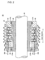
- FIG.2 is a cross-sectional view of the radial piston hydraulic machine according to an embodiment.
- a hydraulic machine 202 comprises a plurality of pistons 22 each disposed along the radial direction of the hydraulic machine 20, and a cylinder block 26 comprising a plurality of cylinders 24 slidably holding the plurality of pistons 22, respectively.
- Each of the pistons 22 is slidably provided in each of the cylinders 24.
- Each of the pistons 24 is guided by each of the cylinders 22 to reciprocate along the radial direction of the hydraulic machine 20.
- the reciprocating motion of the piston 22 which accompanies cyclic volume change of the hydraulic chamber 25 is convertible into a rotational motion of a cam 29, and vice versa.
- the rotational motion of the cam 29 rotating with the rotation shaft 28 of the hydraulic machine 20 is converted into reciprocating motion of the piston 22, and the volume of the hydraulic chamber 25 changes cyclically to generate high pressure operating oil (pressurized oil) in the hydraulic chamber 25.
- the hydraulic machine 20 is a hydraulic motor
- the reciprocating motion of the piston 22 occurs in response to feeding of the pressurized oil into the hydraulic chamber 25, and then the reciprocating motion is converted into the rotational motion of the cam 29.
- the rotation shaft 28 of the hydraulic machine 20 rotates with the cam 29.
- the energy is converted between rotational energy (mechanical energy) of the rotation shaft 28 of the hydraulic machine 20 and fluid energy of the operating oil, and hence the hydraulic machine 20 is capable of serving as the hydraulic pump or the hydraulic motor as desired.
- the cam 29 is configured to rotate with the rotation shaft 28 as illustrated in FIG.2 .
- This cam 29 is a ring cam having a cam surface that contacts the roller 23 provided at the piston 22 and having a wave-like cross-sectional shape.
- at least one bearing 27A may be provided between the cam 29 and the cylinder block 26 to generate the rotational force of the cam 29 relative to the roller 23.
- At least one inner oil path 30 (30A, 30B) communicating with a plurality of the hydraulic chambers 25 is formed.
- a plurality of the inner oil paths 30 (30A, 30B) is provided along the axial direction of the hydraulic machine 20, and annular collecting paths 35 (35A, 35B) are formed in an annular end plate 34 to communicate with the inner oil paths 30 (30A, 30B), respectively.
- the endplate 34 is an annular plate member attached to an end of the cylinder block 26.
- a bearing 27B is provided between the endplate 34 and the cam 29, and the endplate 34 can be maintained in a stationary state without being affected by the rotational motion of the cam 29.
- the annular collecting paths 35 (35A, 35B) inside the endplate 34 are, respectively, connected to outer pipes 36 (36A, 36B). In this manner, each of the hydraulic chambers 25 is configured to communicate with the outer pipes 36 (36A, 36B) via the inner oil paths 30 (30A, 30B) and the annular collecting paths 35 (35A, 35B).
- the cylinder block 26 includes a plurality of cylinder sleeves 40 having the plurality of cylinders 24, respectively, and a cylinder block body 50 having a plurality of sleeve holes 52 into which the plurality of cylinder sleeves 40 is inserted, respectively.
- the cylinder block 26 serves to form the cylinder 24 as the slide part for guiding the piston 22 slidably and also serves to form a structure for supporting the cylinder 24.
- the functions expected in the cylinder block 26 can be shared between the cylinder sleeve 40 and the cylinder block body 50. This enables designing of the cylinder sleeve 40 and the cylinder block body 50 according to their respective functions, hence achieving reduced weight of the cylinder block 26 as a whole.
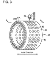
- FIG.3 is an oblique view of the cylinder block according to one embodiment.
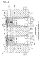
- FIG.4 is a cross-sectional view of the cylinder block of FIG.3 taken along line A-A of FIG.3 .
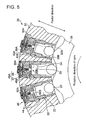
- FIG.5 is a cross-sectional view of the cylinder block of FIG.3 taken along a radial direction of the cylinder block.
- the cylinder block body 50 may be an annular member having both at least one inner oil path 30 (30A, 30B) and a plurality of the sleeve holes 52. Further, it may adopt a cylinder block body 50 which is continuous over the entire periphery in the circumferential direction of the hydraulic machine 20.
- the cylinder sleeve 40 comprises at least one annular groove 42 (42A, 42B).
- the at least one annular groove 42 (42A, 42B) is formed on an outer peripheral surface of the cylinder sleeve 40 and opens to the at least one inner oil path 30 (30A, 30B).
- an annular seal member 44 provided on an outer peripheral surface of the cylinder sleeve 40 to seal a gap between the cylinder sleeve 40 and the sleeve hole 52.
- a communication path 46 (46A, 46B) is provided for communication between each of the annular grooves 42 (42A, 42B) and the hydraulic chamber 25.
- a valve 60 (60A, 60B) is provided for switching the state of communication between the inner oil path 30 (30A, 30B) of the valve block 26 and the hydraulic chamber 25.
- the at least one inner oil path 30 (30A, 30B) includes the oil supply path 30A for supplying the operating oil to the hydraulic chamber 25 and the oil discharge path 30B for discharging the operating oil from the hydraulic chamber 25.
- the at least one annular groove 42 provided in the cylinder sleeve 40 includes an oil supply groove 42A opening to the oil supply path 30A inside the cylinder block body 51, and an oil discharge groove 42B opening to the oil discharge path 30B inside the cylinder block body 51.
- the communication path 46 includes an oil supply communication path 46A for communication between the hydraulic chamber 25 and the oil supply groove 42A via the oil supply valve 60A, and an oil discharge communication path 46B for communication between the hydraulic chamber 25 and the oil discharge groove 42B via the oil discharge groove 69B.
- the oil supply valve 60A and the oil discharge valve 60B are incorporated in the cylinder sleeve 40 such that the oil supply valve 60A and the oil discharge valve 60B are aligned in the radial direction of the hydraulic chamber 20, and the valve element 62A of the oil supply valve 60A lays over the valve element 62B of the oil discharge valve 60B with respect to the radial direction of the hydraulic machine 20.
- the oil supply groove 42A and the oil discharge grove 42B are provided at different positions in the radial direction of the hydraulic machine 20 on the outer peripheral surface of each of the cylinder sleeves 40.
- the communication path 46A corresponding to the oil supply valve 60A located farther from the hydraulic chamber 25 includes a first communication path 47 extending along the direction perpendicular to the radial direction of the hydraulic machine 20 and a second communication path 48 extending along the radial direction of the hydraulic machine 20.
- the oil discharge communication path 46B corresponding to the oil discharge valve 60 disposed nearer to the hydraulic chamber 25 extends along the direction perpendicular to the radial direction of the hydraulic chamber while avoiding the second communication path 48 of the oil supply communication path 46A.
- the hydraulic machine 20 is a hydraulic pump
- the oil supply valve 60A when the oil supply valve 60A is opened, the operating oil from the oil supply path 30A inside the cylinder block body 50 is introduced into the hydraulic chamber 25 via the oil supply groove 42A and the oil supply communication path 46A. Then, the operating oil introduced to the hydraulic chamber 25 is compressed and pressurized by volume reduction of the hydraulic chamber 25 in response to the movement of the piston 22 moving from the bottom dead center to the top dead center.
- the high pressure operating oil (pressurized oil) obtained in this manner is then drawn, by opening of the oil discharge valve 60B, to the oil discharge path 30B inside the cylinder block body 50 via the oil discharge communication path 46B and the oil discharge groove 42B.
- a plurality of axial-direction hole arrays 53 is provided in the circumferential direction of the hydraulic machine 20.
- Each of the axial-direction hole arrays 53 is formed by a plurality of the sleeve holes 52 aligned along the axial direction of the hydraulic machine 20.
- a plurality of the oil supply paths 30A and a plurality of oil discharge paths 30B extend along the axial direction of the hydraulic machine 20 as illustrated in FIG.4 and FIG.5 .
- Each of the oil supply paths 30A and each of the oil discharge paths 30B formed in the cylinder block body 50 open to the oil supply grooves 42A and the oil discharge grooves 42B of a plurality of the cylinder sleeves 40 inserted in a plurality of the sleeve holes 52 belonging to each of the axial-direction hole arrays 53, and communicate with corresponding hydraulic chambers 25 of the axial-direction hole array 53.
- each of the hydraulic chambers 25 may communicate with a plurality of the oil supply paths 30 and a plurality of the oil discharge paths 30B.
- various element such as a side force from the cam 29 may cause displacement of the roller 23 in the axial direction (the width direction of the roller).
- the radial piston hydraulic machine of this embodiment is provided with a roller displacement regulating part for regulating displacement of the roller 23 in the axial direction.
- FIG.6A is an oblique view of the cylinder block according to one embodiment
- FIG.6B is a plan view of this cylinder sleeve.
- the roller 23 comprises a roller body 23A having an outer peripheral surface which contacts the cam 29, and a pair of end surfaces 23B, 23B formed on both sides of the roller body 23A.
- Each of the end surfaces 23B, 23B may have a crowned peripheral edge portion so as to suppress increase of contact pressure at the peripheral edge portion belonging to each of the end surfaces 23B, 23B of the roller 23 when the roller 23 contacts the cam surface.
- a roller displacement regulating part 70 is provided in each of the pistons 22.
- the roller displacement regulating part 70 is configured to contact a region of at least one end surface 23B of each of the rollers 23, exclusive of the peripheral edge portion, so as to regulate the axial displacement of the roller 23.
- the peripheral edge portion of the roller 23 refers to a section in the vicinity of a peripheral edge 23C disposed at the outermost periphery of the end surface 23B of the roller 23, the section including the peripheral edge 23C. Therefore, the region of at least one of the end surfaces 23B of the roller 23 except the peripheral edge portion is a region nearer to the rotation center O side of the roller 23 than the peripheral-edge inclusive section in the vicinity of the peripheral edge.
- roller displacement regulating part 70 By providing the roller displacement regulating part 70 in the piston 22 in this manner, there is no relative movement between the roller 23 and the roller displacement regulating part 70 in the rotation direction of the cam 29 when the cam 29 rotates. Thus, it is possible to suppress friction wear of the roller 23 and the roller displacement regulating part 70. Further, as the roller displacement regulating part 70 is configured to contact the region, exclusive of the peripheral edge portion, of at least one of the end surfaces 23B of the roller 23, it is possible to avoid contact of the roller displacement regulating part 70 with the peripheral edge portion whose circumferential speed is high and also possible to reduce frictional wear of the roller 23 and the roller displacement regulating part 70.
- the roller displacement regulating part 70 includes a pair of arms 72, 72 extending from each of the pistons 22 to the end surfaces 23B, 23B of each of the rollers 23, and a pair of protrusion 74, 74 provided on the pair of arms 72, 72 to serve as a pair of contact parts, respectively.
- the arm 72 may comprise a first section 72A attached to the outer peripheral surface of the piston 22 and extending along the axial direction of the roller 23 from the piston 22, and a second section 72B connected to the first section 72A via a bending portion and extending in the radial direction of the roller 23.
- the protrusion 74 is provided protruding toward the end surface 23B of the roller 23.
- the pair of contact parts is constituted by the pair of protrusions 74, 74 in the above manner, it is possible to simplify the structure of the section where the roller 23 contacts the roller displacement regulating part 70, and to reduce the production cost.
- the first section 72A may be fastened to the outer peripheral surface of the piston 22 by a bolt (see FIG.8 , FIG.9 and FIG.10 ).
- the roller displacement regulating part 70 can be configured to be detachable at low cost and the roller displacement regulating part 70 can be replaced easily as well.
- the roller 23 comprises a receiving part 23D arranged in a place (at a rotation center O of the roller 23) where the roller 23 contacts the protrusion 74.
- the receiving part 23D is made of a material which has a lower frictional resistance than the end surface 23B of the roller 23 (exclusive of the receiving part 23D).
- the material constituting the end surface 23B of the roller 23 may be different from the material constituting the receiving part 23D, or a coating for reducing the frictional resistance may be applied on the surface of the receiving part 23D.
- At least one of the pair of protrusions 74, 74 may be configured to contact the rotation center O of the roller 23 on the end surface 23B of the roller 23.
- the circumferential speed is faster on the peripheral edge 23C side of the end surface 23B belonging to the roller 23, and the circumferential speed decreases with distance to the rotation center O from the peripheral edge 23C. Therefore, by configuring at least one of the pair of protrusions 74, 74 to contact the section of the end surface 23 of the roller 23, where the circumferential speed is zero (the roller rotation center O), it is possible to suppress frictional wear of the roller 23 and the roller displacement regulating part 70 caused by the rotational motion of the roller 23.
- a distance between the pair of protrusions 74, 74 may be larger than a distance between the end surfaces 23B, 23B of the roller 23. Specifically, it may be configured so that, when one of the protrusions 74 contacts one of the end surfaces 23B, there is a clearance between the other of the protrusions 74 and the other of the end surfaces 23B.
- the positions of the pair of protrusions 74 are set corresponding to an allowable range of the axial displacement of the roller 23 relative to the cam 29. As a result, it is possible to further suppress the frictional wear of the protrusion 74 of the piston 22 and the end surface 23B of the roller 23.
- a depression may be provided on the end surface 23B of the roller 23 where the protrusion 74 contacts (a position corresponding to the rotation center O of the roller 23).
- the protrusion 74 is positioned such as to engage with the depression.
- the depression may be provided on each of the end surfaces 23B of the roller 23 so that the protrusions 74, 74 are in constant engagement with the protrusions 74, 74.
- the roller 23 can be retained to the piston 22 side via the roller displacement regulating part 70. Specifically, as the protrusion 74 is in engagement with the roller 23, the roller 23 moves with the piston 22 when the piston 22 moves in the axial direction.
- the protrusion may be provided on the roller 23 side.
- the protrusion is provided at the rotation axis O of the roller 23 on the end surfaces 23B, 23B of the roller 23.
- the contact part of the roller displacement regulating part 70 with respect to the roller 23 is a tip portion of the arm 72.
- a pair of notches 41, 41 is formed in places of the cylinder sleeve 40 corresponding to the pair of roller displacement regulating parts 70, 70 (the arms 72, 72). In the drawing, only one of the notches 41 is illustrated.
- the cylinder sleeve 40 comprises an upper cylindrical part 40A disposed on an outer circumferential side of the cylinder block 50 and a lower cylindrical part 40B disposed on an inner circumferential side of the cylinder block 50. Between the upper cylindrical part 40A and the lower cylindrical part 40B, a stepped portion 40C is provided.
- the sleeve hole 52 provided in the cylinder block 50 comprises an upper hole part 52A and a lower hole part 52B. Between the upper hole part 52A and the lower hole part 52B, a stepped portion 52C is provided.
- the hole of the upper hole part 52A has a cylindrical shape corresponding to the shape of the upper cylindrical part 40A, and the hole of the lower hole part 52B may be formed by a plurality of curved surface on the outer side. Diameter D 1 of the upper hole part 52A is approximately the same as the diameter of the upper cylindrical part 40A. Further, the lower hole part 52B has short diameter D 2 which is larger than width of the piston 22 and the roller 23 in the rotation direction of the cam, and long diameter D 3 which is larger than width of the pair of roller displacement regulating parts 70, 70 (arms 72, 72). Therefore, the lower hole part 52B is configured not to contact the roller 23 and the pair of arms 72, 72 at the reciprocating motion of the piston 22 and the roller 23. With this configuration, it is possible to reduce the volume of the the sleeve holes 52 occupying the cylinder block 50 on the inner peripheral side of the cylinder block 50 where components are intensively arranged.
- FIG.7A is an oblique view of the cylinder block according to this embodiment
- FIG.7B is a plan view of the cylinder sleeve according to this embodiment.
- the cylinder sleeve 40 is formed into a stepless cylindrical shape.
- the sleeve hole 52 is formed into a columnar shape having diameter D 4 corresponding to the cylinder sleeve 40.
- the diameter D 4 is larger than length L of a diagonal line of the roller 23.
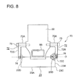
- the roller displacement regulating part may be configured as illustrated in FIG.8 to FIG.10 .
- FIG.8 is a front view of the piston and the roller according to another embodiment.
- FIG.9 is a side view of the piston and the roller according to another embodiment.
- FIG.10 is a front view of the piston and the roller according to another embodiment.
- one of the pair of roller displacement regulating parts is illustrated as a fragmentary cross-sectional view.
- the roller displacement regulating part 70 comprises a pair of arms 72, 72 extending from each of the pistons 22 to the end surfaces 23B, 23B of each of the rollers 23, and a pair of contact parts which is provided in the pair of arms72, 72, respectively, and a pair of balls 76, 76 provided on the pair of arms 72, 72, respectively, to serve as a pair of contact parts.
- the arm 72 may comprise a first section 72A attached to the outer peripheral surface of the piston 22 and extending along the axial direction of the roller 23 from the piston 22, and a second section 72B connected to the first section 72A via a bending portion and extending in the radial direction of the roller 23.
- the first section 72A may be fastened to the outer peripheral surface of the piston 22 by a bolt 75.
- the arm 72 can be configured to be detachable from the piston 22.
- the ball 76 is accommodated in a recess 72C formed in a tip portion of the second section 72B and is configured to rollably contact the end surface 23B of the roller 23.
- the ball 76 rolls in response to rotation of the roller 23.
- it is mainly rolling friction that takes place between the roller 23 and the roller displacement regulating part 70.
- the rolling friction is smaller than a sliding friction, and thus it is possible to further reduce frictional wear of the roller 23 and the roller displacement regulating part 70 (the tip portion of the arm 72 and the ball 76) caused by the rotational movement of the roller 23.
- a receiving part 23D may be provided in the end surface 23B of the roller 23 where the ball 76 contacts the roller 23 (at the rotation center O of the roller 23).
- the receiving part 23D is made of a material which has a lower frictional resistance than the end surface 23B of the roller 23 (exclusive of the receiving part 23D).
- At least one of the pair of balls 76, 76 may be configured to contact the rotation center O of the roller 23 on the end surface 23B of the roller 23. As a result, it is possible to suppress frictional wear of the roller 23 and the roller displacement regulating part 70 (the tip portion of the arm 72 and the ball 76) caused by the rotational movement of the roller 23.
- a depression may be provided on the end surface 23B of the roller 23 where the ball 76 contacts (a position corresponding to the rotation center O of the roller 23).
- a ball 78 is retained to the roller 23 side.
- the ball 78 is accommodated in a recess 23E provided at the rotation center O on the end surface 23B of the roller 23, and this ball 78 is configured to rollably contact the tip portion 73 of the arm 72.
- the hydraulic machine 20 may have the configuration for supplying lubricating oil to the piston 22 and the roller 23.
- FIG.11 is a schematic view of an engagement surface between the piston with respect to the roller.
- the piston 22 is provided with an inner flow path 80 for introducing operating oil from the hydraulic chamber (see FIG.2 , FIG.4 and FIG.5 ) to the engagement surface between the piston 22 and the roller 23.
- the piston 22 is provided with at least one oil groove 82 formed facing the engagement surface. This oil groove 82 communicates with the inner flow path 80.
- the operating oil in the hydraulic chamber 25 is supplied to the oil groove 82 via the inner flow path 80 provided in the piston 22.
- the oil groove 82 is configured by an annular groove portion 82A and a transverse groove portion 82B traversing the annular groove portion 82A.
- the operating oil supplied from the inner flow path 80 is led to the annular groove portion 82A and the transverse groove portion 82B.
- the operating can be supplied effectively to the engagement surfaces between the piston 22 and the roller 23 as the lubricating oil, and thus a hydrostatic oil film can be formed by oil pressure in a stable manner.
- another inner flow path 84 may be provided in the piston 22.
- This inner flow path 84 communicates with the oil groove 86 formed in the outer peripheral surface of the piston 22.
- the inner flow paths 80, 84 each have a passage diameter sufficiently smaller than a passage diameter of the first communication path 47 and the second communication path 48 that are illustrated in FIG.4 and FIG.5 .
- FIG.12 is a cross-sectional view of the cylinder block according to another embodiment, taken along the axial direction of the cylinder block.
- a depression 92 is provided on the outer peripheral surface of the roller 23 along the circumferential direction of the roller 23.
- the depression 92 may be formed in a continuous manner over the entire circumference of the roller 23 in the circumferential direction. Illustrated in the drawing is the case where one depression 92 is provided. However, this is not restrictive and a plurality of depressions 92 may be provided.
- a roller displacement regulating part 90 is provided on the piston 22 and includes a projection 94 which is contactable with the depression 92.
- a plurality of projections 94 may be provided corresponding to the plurality of depressions 92.
- the roller 23 rotates in the state where at least one projection 94 provided on the piston 22 engages with at least one depression 92 provided on the roller 23 and thus, a relative position of the roller 23 relative to the piston 22 can be held constant.
- the position of the roller 23 can be constant relative to a position of the cam surface in the width direction. Therefore, the roller 23 can be held at an appropriate position relative to the cam surface.
- the arm 72 serving as the above-described roller displacement regulating part 70 may be provided.
- an inner flow path 96 may be provided in the piston 22 for communication between: the hydraulic chamber 25 formed by the piston 22 and the cylinder 24 and; and a space between the piston 22 and the roller 23.
- the inner flow path 96 has a passage diameter sufficiently smaller than a passage diameter of the first communication path 47 and the second communication path 48.
- the operating oil is supplied from the hydraulic chamber 25 through the inner flow path 96 to between the piston 22 and the roller 23, and this supplied operating oil serves as the lubricating oil.
- the inner flow path 96 may be configured to open to the engagement part between the projection of the piston 22 and the depression of the roller 23.
- roller displacement regulating part 70, 90 for regulating the axial displacement of the roller 23.
- the roller displacement regulating part 70, 90 is configured to contact a region of at least one end surface 23B of the roller 23, exclusive of the peripheral edge portion, it is possible to avoid contact of the roller displacement regulating part 70, 90 with the peripheral edge portion of the end surface 23B, where the circumferential speed is high, thereby reducing frictional wear of the roller 23 and the roller displacement regulating part 70, 90.
- the roller displacement regulating part 70, 90 is provided on each of the pistons 22, it is possible to avoid weight increase of the radial piston hydraulic machine 20, compared to the case where the side panels are provided on both sides of the cam surface.
- the rotation center O of the roller 23 is located on the center axis L of the cylinder sleeve 40.
- a roller 23' may be arranged such that the rotation center O of the roller 23' is positioned downstream relative to the center axis L of the cylinder sleeve 40 in the rotation direction of the cam 29 (a direction of an arrow in the drawing).
- FIG.13 is across -sectional view of the cylinder block according to another embodiment, taken along the radial direction.
- FIG.14 is an explanatory view of a configuration of the roller according to another embodiment.
- the dotted line indicates the roller 23 in the case where the rotation center O is positioned on the center axis L of the cylinder sleeve 40. Further, the double-dotted line in FIG. 14 indicates a roller 23" in a skewing state.
- the roller 23' is arranged so that the rotation center O is positioned downstream relative to the center axis L by distance D in the rotation direction of the cam 29 in a normal state (in the state where the roller 23' is not skewed).
- a normal state in the state where the roller 23' is not skewed.
- the position of the roller 23' changes to the position of the roller 23" indicated by the double dotted line in the drawing.
- force F in a direction opposite to the rotation direction of the cam 29 acts on a gravity center position C' of the skewed roller 23".
- This force F contains a component F 1 in the direction of the rotation center O' of the roller 23" and a component F 2 in the direction perpendicular to the rotation center O'.
- the term "along" used in the description of the above embodiments not just refers to a state of being strictly parallel in a geometric sense with respect to a reference direction or object as a reference but also includes a state of being at an angle to a certain extent with respect the reference direction or object (e.g. 30° or less).
Landscapes
- Engineering & Computer Science (AREA)
- Mechanical Engineering (AREA)
- General Engineering & Computer Science (AREA)
- Chemical & Material Sciences (AREA)
- Combustion & Propulsion (AREA)
- Life Sciences & Earth Sciences (AREA)
- Sustainable Development (AREA)
- Sustainable Energy (AREA)
- Power Engineering (AREA)
- Reciprocating Pumps (AREA)
- Wind Motors (AREA)
- Hydraulic Motors (AREA)
Priority Applications (1)
| Application Number | Priority Date | Filing Date | Title |
|---|---|---|---|
| EP13199744.7A EP2749769B1 (fr) | 2012-12-28 | 2013-12-30 | Machine hydraulique à pistons radiaux et générateur de turbine éolienne |
Applications Claiming Priority (2)
| Application Number | Priority Date | Filing Date | Title |
|---|---|---|---|
| JP2012288350 | 2012-12-28 | ||
| JP2013069673A JP2014141957A (ja) | 2012-12-28 | 2013-03-28 | ラジアルピストン式油圧機械および風力発電装置 |
Publications (2)
| Publication Number | Publication Date |
|---|---|
| EP2749767A1 true EP2749767A1 (fr) | 2014-07-02 |
| EP2749767B1 EP2749767B1 (fr) | 2017-04-19 |
Family
ID=49816876
Family Applications (1)
| Application Number | Title | Priority Date | Filing Date |
|---|---|---|---|
| EP13198253.0A Not-in-force EP2749767B1 (fr) | 2012-12-28 | 2013-12-19 | Machine hydraulique à pistons radiaux et générateur de turbine éolienne |
Country Status (2)
| Country | Link |
|---|---|
| EP (1) | EP2749767B1 (fr) |
| JP (1) | JP2014141957A (fr) |
Cited By (1)
| Publication number | Priority date | Publication date | Assignee | Title |
|---|---|---|---|---|
| WO2016097230A1 (fr) * | 2014-12-17 | 2016-06-23 | Poclain Hydraulics Industrie | Piston à galet monobloc et procédé associé |
Families Citing this family (1)
| Publication number | Priority date | Publication date | Assignee | Title |
|---|---|---|---|---|
| JP6321700B2 (ja) * | 2016-02-26 | 2018-05-09 | 三菱重工業株式会社 | 油圧機械および風力発電装置 |
Citations (12)
| Publication number | Priority date | Publication date | Assignee | Title |
|---|---|---|---|---|
| CH598488A5 (en) * | 1976-07-15 | 1978-04-28 | Cyphelly Ivan J | Positive displacement pump or motor |
| FR2582058A1 (fr) * | 1985-05-15 | 1986-11-21 | Poclain Hydraulics Sa | Mecanisme hydraulique, moteur ou pompe, muni de rouleaux montes sur les pistons et de moyens de maintien en position desdits rouleaux |
| DE19810372A1 (de) * | 1998-03-10 | 1999-09-16 | Mannesmann Rexroth Ag | Radialkolbenmotor mit Rollenführung |
| WO2000053925A1 (fr) * | 1999-03-11 | 2000-09-14 | Mapple Technology Ltd. | Bloc moteur rotatif |
| US6834575B2 (en) | 2000-04-21 | 2004-12-28 | Jurij Manfreda | Piston assembly for a radial piston hydraulic motor |
| JP2009531596A (ja) | 2006-03-31 | 2009-09-03 | ポクラン イドロリク アンドゥストリ | ラジアルピストンを有する油圧モータ用のピストン、及び、その製造方法 |
| DE102008001871A1 (de) * | 2008-05-20 | 2009-11-26 | Robert Bosch Gmbh | Kraftstoffhochdruckpumpe |
| JP2010019192A (ja) | 2008-07-11 | 2010-01-28 | Toyota Motor Corp | ピストンポンプ及びそれを備えた動力伝達装置、並びにピストンモータ |
| US20100040470A1 (en) | 2008-08-13 | 2010-02-18 | Jacob Johannes Nies | Wind energy system with fluid-working machine with non-symmetric actuation |
| WO2011104544A2 (fr) * | 2010-02-23 | 2011-09-01 | Artemis Intelligent Power Limited | Machine à fluide de travail à piston radiaux et à déplacement variable |
| DE102010032057A1 (de) * | 2010-07-23 | 2012-01-26 | Robert Bosch Gmbh | Radialkolbenmaschine und Kolben für eine derartige Radialkolbenmaschine |
| DE102010038553A1 (de) * | 2010-07-28 | 2012-02-02 | Robert Bosch Gmbh | Stößelbaugruppe für eine Hochdruckpumpe eines Kraftstoffeinspritzsystems einer Brennkraftmaschine |
-
2013
- 2013-03-28 JP JP2013069673A patent/JP2014141957A/ja active Pending
- 2013-12-19 EP EP13198253.0A patent/EP2749767B1/fr not_active Not-in-force
Patent Citations (12)
| Publication number | Priority date | Publication date | Assignee | Title |
|---|---|---|---|---|
| CH598488A5 (en) * | 1976-07-15 | 1978-04-28 | Cyphelly Ivan J | Positive displacement pump or motor |
| FR2582058A1 (fr) * | 1985-05-15 | 1986-11-21 | Poclain Hydraulics Sa | Mecanisme hydraulique, moteur ou pompe, muni de rouleaux montes sur les pistons et de moyens de maintien en position desdits rouleaux |
| DE19810372A1 (de) * | 1998-03-10 | 1999-09-16 | Mannesmann Rexroth Ag | Radialkolbenmotor mit Rollenführung |
| WO2000053925A1 (fr) * | 1999-03-11 | 2000-09-14 | Mapple Technology Ltd. | Bloc moteur rotatif |
| US6834575B2 (en) | 2000-04-21 | 2004-12-28 | Jurij Manfreda | Piston assembly for a radial piston hydraulic motor |
| JP2009531596A (ja) | 2006-03-31 | 2009-09-03 | ポクラン イドロリク アンドゥストリ | ラジアルピストンを有する油圧モータ用のピストン、及び、その製造方法 |
| DE102008001871A1 (de) * | 2008-05-20 | 2009-11-26 | Robert Bosch Gmbh | Kraftstoffhochdruckpumpe |
| JP2010019192A (ja) | 2008-07-11 | 2010-01-28 | Toyota Motor Corp | ピストンポンプ及びそれを備えた動力伝達装置、並びにピストンモータ |
| US20100040470A1 (en) | 2008-08-13 | 2010-02-18 | Jacob Johannes Nies | Wind energy system with fluid-working machine with non-symmetric actuation |
| WO2011104544A2 (fr) * | 2010-02-23 | 2011-09-01 | Artemis Intelligent Power Limited | Machine à fluide de travail à piston radiaux et à déplacement variable |
| DE102010032057A1 (de) * | 2010-07-23 | 2012-01-26 | Robert Bosch Gmbh | Radialkolbenmaschine und Kolben für eine derartige Radialkolbenmaschine |
| DE102010038553A1 (de) * | 2010-07-28 | 2012-02-02 | Robert Bosch Gmbh | Stößelbaugruppe für eine Hochdruckpumpe eines Kraftstoffeinspritzsystems einer Brennkraftmaschine |
Cited By (2)
| Publication number | Priority date | Publication date | Assignee | Title |
|---|---|---|---|---|
| WO2016097230A1 (fr) * | 2014-12-17 | 2016-06-23 | Poclain Hydraulics Industrie | Piston à galet monobloc et procédé associé |
| FR3030665A1 (fr) * | 2014-12-17 | 2016-06-24 | Poclain Hydraulics Ind | Piston a galet monobloc et procede associe |
Also Published As
| Publication number | Publication date |
|---|---|
| EP2749767B1 (fr) | 2017-04-19 |
| JP2014141957A (ja) | 2014-08-07 |
Similar Documents
| Publication | Publication Date | Title |
|---|---|---|
| US11008863B2 (en) | Piston arrangement | |
| EP2749767B1 (fr) | Machine hydraulique à pistons radiaux et générateur de turbine éolienne | |
| EP2796714B1 (fr) | Machine hydraulique de type à pistons radiaux, transmission hydraulique et générateur de turbine éolienne | |
| EP2955374B1 (fr) | Machine hydraulique à pistons radiaux et appareil de génération d'énergie éolienne | |
| US20160256993A1 (en) | Oscillatingly Driven Machine Tool | |
| EP1623119B1 (fr) | Ameliorations apportees a des cames et des galets suiveurs | |
| EP2726737B1 (fr) | Moteur ou pompe hydraulique et génératrice de turbine éolienne | |
| EP3141748B1 (fr) | Machine hydraulique de type pistons radiaux et appareil de génération d'énergie éolienne | |
| EP2739846B1 (fr) | Machine de travail à fluide et génératrice de turbine éolienne | |
| EP2821648B1 (fr) | Machine hydraulique et dispositif de génération de puissance à énergie récupérée | |
| EP2749768B1 (fr) | Machine hydraulique à pistons radiaux et générateur de turbine éolienne | |
| JP6434854B2 (ja) | ラジアルピストン式油圧機械及びこれを備えた風力発電装置、並びに油圧機械のメンテナンス方法 | |
| JP6227308B2 (ja) | 回転機械 | |
| JP2014129782A (ja) | ラジアルピストン式油圧機械および風力発電装置 | |
| WO2015069126A1 (fr) | Moteur à vapeur sans huile avec piston oscillant | |
| JP2014129770A (ja) | ラジアルピストン式油圧機械、その組立て方法及び風力発電装置 |
Legal Events
| Date | Code | Title | Description |
|---|---|---|---|
| 17P | Request for examination filed |
Effective date: 20131219 |
|
| AK | Designated contracting states |
Kind code of ref document: A1 Designated state(s): AL AT BE BG CH CY CZ DE DK EE ES FI FR GB GR HR HU IE IS IT LI LT LU LV MC MK MT NL NO PL PT RO RS SE SI SK SM TR |
|
| AX | Request for extension of the european patent |
Extension state: BA ME |
|
| PUAI | Public reference made under article 153(3) epc to a published international application that has entered the european phase |
Free format text: ORIGINAL CODE: 0009012 |
|
| R17P | Request for examination filed (corrected) |
Effective date: 20141216 |
|
| RBV | Designated contracting states (corrected) |
Designated state(s): AL AT BE BG CH CY CZ DE DK EE ES FI FR GB GR HR HU IE IS IT LI LT LU LV MC MK MT NL NO PL PT RO RS SE SI SK SM TR |
|
| 17Q | First examination report despatched |
Effective date: 20160222 |
|
| GRAP | Despatch of communication of intention to grant a patent |
Free format text: ORIGINAL CODE: EPIDOSNIGR1 |
|
| INTG | Intention to grant announced |
Effective date: 20161207 |
|
| GRAS | Grant fee paid |
Free format text: ORIGINAL CODE: EPIDOSNIGR3 |
|
| GRAA | (expected) grant |
Free format text: ORIGINAL CODE: 0009210 |
|
| AK | Designated contracting states |
Kind code of ref document: B1 Designated state(s): AL AT BE BG CH CY CZ DE DK EE ES FI FR GB GR HR HU IE IS IT LI LT LU LV MC MK MT NL NO PL PT RO RS SE SI SK SM TR |
|
| REG | Reference to a national code |
Ref country code: GB Ref legal event code: FG4D |
|
| REG | Reference to a national code |
Ref country code: CH Ref legal event code: EP |
|
| REG | Reference to a national code |
Ref country code: AT Ref legal event code: REF Ref document number: 886237 Country of ref document: AT Kind code of ref document: T Effective date: 20170515 |
|
| REG | Reference to a national code |
Ref country code: IE Ref legal event code: FG4D |
|
| REG | Reference to a national code |
Ref country code: DE Ref legal event code: R096 Ref document number: 602013019964 Country of ref document: DE |
|
| REG | Reference to a national code |
Ref country code: NL Ref legal event code: MP Effective date: 20170419 |
|
| REG | Reference to a national code |
Ref country code: LT Ref legal event code: MG4D |
|
| REG | Reference to a national code |
Ref country code: AT Ref legal event code: MK05 Ref document number: 886237 Country of ref document: AT Kind code of ref document: T Effective date: 20170419 |
|
| PG25 | Lapsed in a contracting state [announced via postgrant information from national office to epo] |
Ref country code: NL Free format text: LAPSE BECAUSE OF FAILURE TO SUBMIT A TRANSLATION OF THE DESCRIPTION OR TO PAY THE FEE WITHIN THE PRESCRIBED TIME-LIMIT Effective date: 20170419 |
|
| PG25 | Lapsed in a contracting state [announced via postgrant information from national office to epo] |
Ref country code: HR Free format text: LAPSE BECAUSE OF FAILURE TO SUBMIT A TRANSLATION OF THE DESCRIPTION OR TO PAY THE FEE WITHIN THE PRESCRIBED TIME-LIMIT Effective date: 20170419 Ref country code: NO Free format text: LAPSE BECAUSE OF FAILURE TO SUBMIT A TRANSLATION OF THE DESCRIPTION OR TO PAY THE FEE WITHIN THE PRESCRIBED TIME-LIMIT Effective date: 20170719 Ref country code: ES Free format text: LAPSE BECAUSE OF FAILURE TO SUBMIT A TRANSLATION OF THE DESCRIPTION OR TO PAY THE FEE WITHIN THE PRESCRIBED TIME-LIMIT Effective date: 20170419 Ref country code: FI Free format text: LAPSE BECAUSE OF FAILURE TO SUBMIT A TRANSLATION OF THE DESCRIPTION OR TO PAY THE FEE WITHIN THE PRESCRIBED TIME-LIMIT Effective date: 20170419 Ref country code: LT Free format text: LAPSE BECAUSE OF FAILURE TO SUBMIT A TRANSLATION OF THE DESCRIPTION OR TO PAY THE FEE WITHIN THE PRESCRIBED TIME-LIMIT Effective date: 20170419 Ref country code: GR Free format text: LAPSE BECAUSE OF FAILURE TO SUBMIT A TRANSLATION OF THE DESCRIPTION OR TO PAY THE FEE WITHIN THE PRESCRIBED TIME-LIMIT Effective date: 20170720 Ref country code: AT Free format text: LAPSE BECAUSE OF FAILURE TO SUBMIT A TRANSLATION OF THE DESCRIPTION OR TO PAY THE FEE WITHIN THE PRESCRIBED TIME-LIMIT Effective date: 20170419 |
|
| PG25 | Lapsed in a contracting state [announced via postgrant information from national office to epo] |
Ref country code: SE Free format text: LAPSE BECAUSE OF FAILURE TO SUBMIT A TRANSLATION OF THE DESCRIPTION OR TO PAY THE FEE WITHIN THE PRESCRIBED TIME-LIMIT Effective date: 20170419 Ref country code: BG Free format text: LAPSE BECAUSE OF FAILURE TO SUBMIT A TRANSLATION OF THE DESCRIPTION OR TO PAY THE FEE WITHIN THE PRESCRIBED TIME-LIMIT Effective date: 20170719 Ref country code: PL Free format text: LAPSE BECAUSE OF FAILURE TO SUBMIT A TRANSLATION OF THE DESCRIPTION OR TO PAY THE FEE WITHIN THE PRESCRIBED TIME-LIMIT Effective date: 20170419 Ref country code: RS Free format text: LAPSE BECAUSE OF FAILURE TO SUBMIT A TRANSLATION OF THE DESCRIPTION OR TO PAY THE FEE WITHIN THE PRESCRIBED TIME-LIMIT Effective date: 20170419 Ref country code: LV Free format text: LAPSE BECAUSE OF FAILURE TO SUBMIT A TRANSLATION OF THE DESCRIPTION OR TO PAY THE FEE WITHIN THE PRESCRIBED TIME-LIMIT Effective date: 20170419 Ref country code: IS Free format text: LAPSE BECAUSE OF FAILURE TO SUBMIT A TRANSLATION OF THE DESCRIPTION OR TO PAY THE FEE WITHIN THE PRESCRIBED TIME-LIMIT Effective date: 20170819 |
|
| REG | Reference to a national code |
Ref country code: FR Ref legal event code: PLFP Year of fee payment: 5 |
|
| REG | Reference to a national code |
Ref country code: DE Ref legal event code: R097 Ref document number: 602013019964 Country of ref document: DE |
|
| PG25 | Lapsed in a contracting state [announced via postgrant information from national office to epo] |
Ref country code: EE Free format text: LAPSE BECAUSE OF FAILURE TO SUBMIT A TRANSLATION OF THE DESCRIPTION OR TO PAY THE FEE WITHIN THE PRESCRIBED TIME-LIMIT Effective date: 20170419 Ref country code: RO Free format text: LAPSE BECAUSE OF FAILURE TO SUBMIT A TRANSLATION OF THE DESCRIPTION OR TO PAY THE FEE WITHIN THE PRESCRIBED TIME-LIMIT Effective date: 20170419 Ref country code: DK Free format text: LAPSE BECAUSE OF FAILURE TO SUBMIT A TRANSLATION OF THE DESCRIPTION OR TO PAY THE FEE WITHIN THE PRESCRIBED TIME-LIMIT Effective date: 20170419 Ref country code: CZ Free format text: LAPSE BECAUSE OF FAILURE TO SUBMIT A TRANSLATION OF THE DESCRIPTION OR TO PAY THE FEE WITHIN THE PRESCRIBED TIME-LIMIT Effective date: 20170419 Ref country code: SK Free format text: LAPSE BECAUSE OF FAILURE TO SUBMIT A TRANSLATION OF THE DESCRIPTION OR TO PAY THE FEE WITHIN THE PRESCRIBED TIME-LIMIT Effective date: 20170419 |
|
| PLBE | No opposition filed within time limit |
Free format text: ORIGINAL CODE: 0009261 |
|
| STAA | Information on the status of an ep patent application or granted ep patent |
Free format text: STATUS: NO OPPOSITION FILED WITHIN TIME LIMIT |
|
| PG25 | Lapsed in a contracting state [announced via postgrant information from national office to epo] |
Ref country code: SM Free format text: LAPSE BECAUSE OF FAILURE TO SUBMIT A TRANSLATION OF THE DESCRIPTION OR TO PAY THE FEE WITHIN THE PRESCRIBED TIME-LIMIT Effective date: 20170419 Ref country code: IT Free format text: LAPSE BECAUSE OF FAILURE TO SUBMIT A TRANSLATION OF THE DESCRIPTION OR TO PAY THE FEE WITHIN THE PRESCRIBED TIME-LIMIT Effective date: 20170419 |
|
| 26N | No opposition filed |
Effective date: 20180122 |
|
| PG25 | Lapsed in a contracting state [announced via postgrant information from national office to epo] |
Ref country code: SI Free format text: LAPSE BECAUSE OF FAILURE TO SUBMIT A TRANSLATION OF THE DESCRIPTION OR TO PAY THE FEE WITHIN THE PRESCRIBED TIME-LIMIT Effective date: 20170419 |
|
| REG | Reference to a national code |
Ref country code: CH Ref legal event code: PL |
|
| REG | Reference to a national code |
Ref country code: IE Ref legal event code: MM4A |
|
| PG25 | Lapsed in a contracting state [announced via postgrant information from national office to epo] |
Ref country code: MT Free format text: LAPSE BECAUSE OF NON-PAYMENT OF DUE FEES Effective date: 20171219 Ref country code: LU Free format text: LAPSE BECAUSE OF NON-PAYMENT OF DUE FEES Effective date: 20171219 |
|
| REG | Reference to a national code |
Ref country code: BE Ref legal event code: MM Effective date: 20171231 |
|
| PG25 | Lapsed in a contracting state [announced via postgrant information from national office to epo] |
Ref country code: IE Free format text: LAPSE BECAUSE OF NON-PAYMENT OF DUE FEES Effective date: 20171219 |
|
| PG25 | Lapsed in a contracting state [announced via postgrant information from national office to epo] |
Ref country code: CH Free format text: LAPSE BECAUSE OF NON-PAYMENT OF DUE FEES Effective date: 20171231 Ref country code: BE Free format text: LAPSE BECAUSE OF NON-PAYMENT OF DUE FEES Effective date: 20171231 Ref country code: LI Free format text: LAPSE BECAUSE OF NON-PAYMENT OF DUE FEES Effective date: 20171231 |
|
| PGFP | Annual fee paid to national office [announced via postgrant information from national office to epo] |
Ref country code: DE Payment date: 20181204 Year of fee payment: 6 |
|
| PGFP | Annual fee paid to national office [announced via postgrant information from national office to epo] |
Ref country code: FR Payment date: 20181220 Year of fee payment: 6 Ref country code: GB Payment date: 20181218 Year of fee payment: 6 |
|
| PG25 | Lapsed in a contracting state [announced via postgrant information from national office to epo] |
Ref country code: HU Free format text: LAPSE BECAUSE OF FAILURE TO SUBMIT A TRANSLATION OF THE DESCRIPTION OR TO PAY THE FEE WITHIN THE PRESCRIBED TIME-LIMIT; INVALID AB INITIO Effective date: 20131219 Ref country code: MC Free format text: LAPSE BECAUSE OF FAILURE TO SUBMIT A TRANSLATION OF THE DESCRIPTION OR TO PAY THE FEE WITHIN THE PRESCRIBED TIME-LIMIT Effective date: 20170419 |
|
| PG25 | Lapsed in a contracting state [announced via postgrant information from national office to epo] |
Ref country code: CY Free format text: LAPSE BECAUSE OF NON-PAYMENT OF DUE FEES Effective date: 20170419 |
|
| PG25 | Lapsed in a contracting state [announced via postgrant information from national office to epo] |
Ref country code: MK Free format text: LAPSE BECAUSE OF FAILURE TO SUBMIT A TRANSLATION OF THE DESCRIPTION OR TO PAY THE FEE WITHIN THE PRESCRIBED TIME-LIMIT Effective date: 20170419 |
|
| PG25 | Lapsed in a contracting state [announced via postgrant information from national office to epo] |
Ref country code: TR Free format text: LAPSE BECAUSE OF FAILURE TO SUBMIT A TRANSLATION OF THE DESCRIPTION OR TO PAY THE FEE WITHIN THE PRESCRIBED TIME-LIMIT Effective date: 20170419 |
|
| PG25 | Lapsed in a contracting state [announced via postgrant information from national office to epo] |
Ref country code: PT Free format text: LAPSE BECAUSE OF FAILURE TO SUBMIT A TRANSLATION OF THE DESCRIPTION OR TO PAY THE FEE WITHIN THE PRESCRIBED TIME-LIMIT Effective date: 20170419 |
|
| REG | Reference to a national code |
Ref country code: DE Ref legal event code: R119 Ref document number: 602013019964 Country of ref document: DE |
|
| PG25 | Lapsed in a contracting state [announced via postgrant information from national office to epo] |
Ref country code: AL Free format text: LAPSE BECAUSE OF FAILURE TO SUBMIT A TRANSLATION OF THE DESCRIPTION OR TO PAY THE FEE WITHIN THE PRESCRIBED TIME-LIMIT Effective date: 20170419 |
|
| GBPC | Gb: european patent ceased through non-payment of renewal fee |
Effective date: 20191219 |
|
| PG25 | Lapsed in a contracting state [announced via postgrant information from national office to epo] |
Ref country code: FR Free format text: LAPSE BECAUSE OF NON-PAYMENT OF DUE FEES Effective date: 20191231 Ref country code: DE Free format text: LAPSE BECAUSE OF NON-PAYMENT OF DUE FEES Effective date: 20200701 Ref country code: GB Free format text: LAPSE BECAUSE OF NON-PAYMENT OF DUE FEES Effective date: 20191219 |