EP2749773B1 - Roue et machine rotative dotée de celle-ci - Google Patents
Roue et machine rotative dotée de celle-ci Download PDFInfo
- Publication number
- EP2749773B1 EP2749773B1 EP12861319.7A EP12861319A EP2749773B1 EP 2749773 B1 EP2749773 B1 EP 2749773B1 EP 12861319 A EP12861319 A EP 12861319A EP 2749773 B1 EP2749773 B1 EP 2749773B1
- Authority
- EP
- European Patent Office
- Prior art keywords
- inner diameter
- impeller
- disk
- axis
- rotation shaft
- Prior art date
- Legal status (The legal status is an assumption and is not a legal conclusion. Google has not performed a legal analysis and makes no representation as to the accuracy of the status listed.)
- Not-in-force
Links
- 238000005520 cutting process Methods 0.000 claims description 6
- 230000002093 peripheral effect Effects 0.000 claims description 4
- 238000003466 welding Methods 0.000 description 11
- 238000005452 bending Methods 0.000 description 9
- 238000006073 displacement reaction Methods 0.000 description 5
- 238000005304 joining Methods 0.000 description 3
- 238000012423 maintenance Methods 0.000 description 3
- 238000000034 method Methods 0.000 description 3
- 238000009792 diffusion process Methods 0.000 description 2
- 238000001816 cooling Methods 0.000 description 1
- 230000000694 effects Effects 0.000 description 1
- 238000010438 heat treatment Methods 0.000 description 1
- 238000009434 installation Methods 0.000 description 1
- 238000003754 machining Methods 0.000 description 1
- 238000000465 moulding Methods 0.000 description 1
- 238000013341 scale-up Methods 0.000 description 1
- 238000011144 upstream manufacturing Methods 0.000 description 1
Images


Classifications
-
- F—MECHANICAL ENGINEERING; LIGHTING; HEATING; WEAPONS; BLASTING
- F04—POSITIVE - DISPLACEMENT MACHINES FOR LIQUIDS; PUMPS FOR LIQUIDS OR ELASTIC FLUIDS
- F04D—NON-POSITIVE-DISPLACEMENT PUMPS
- F04D29/00—Details, component parts, or accessories
- F04D29/60—Mounting; Assembling; Disassembling
- F04D29/62—Mounting; Assembling; Disassembling of radial or helico-centrifugal pumps
- F04D29/624—Mounting; Assembling; Disassembling of radial or helico-centrifugal pumps especially adapted for elastic fluid pumps
-
- F—MECHANICAL ENGINEERING; LIGHTING; HEATING; WEAPONS; BLASTING
- F01—MACHINES OR ENGINES IN GENERAL; ENGINE PLANTS IN GENERAL; STEAM ENGINES
- F01D—NON-POSITIVE DISPLACEMENT MACHINES OR ENGINES, e.g. STEAM TURBINES
- F01D5/00—Blades; Blade-carrying members; Heating, heat-insulating, cooling or antivibration means on the blades or the members
- F01D5/30—Fixing blades to rotors; Blade roots ; Blade spacers
-
- F—MECHANICAL ENGINEERING; LIGHTING; HEATING; WEAPONS; BLASTING
- F04—POSITIVE - DISPLACEMENT MACHINES FOR LIQUIDS; PUMPS FOR LIQUIDS OR ELASTIC FLUIDS
- F04D—NON-POSITIVE-DISPLACEMENT PUMPS
- F04D29/00—Details, component parts, or accessories
- F04D29/26—Rotors specially for elastic fluids
- F04D29/266—Rotors specially for elastic fluids mounting compressor rotors on shafts
-
- F—MECHANICAL ENGINEERING; LIGHTING; HEATING; WEAPONS; BLASTING
- F04—POSITIVE - DISPLACEMENT MACHINES FOR LIQUIDS; PUMPS FOR LIQUIDS OR ELASTIC FLUIDS
- F04D—NON-POSITIVE-DISPLACEMENT PUMPS
- F04D29/00—Details, component parts, or accessories
- F04D29/26—Rotors specially for elastic fluids
- F04D29/28—Rotors specially for elastic fluids for centrifugal or helico-centrifugal pumps for radial-flow or helico-centrifugal pumps
- F04D29/284—Rotors specially for elastic fluids for centrifugal or helico-centrifugal pumps for radial-flow or helico-centrifugal pumps for compressors
Definitions
- the present invention is related to an impeller and a rotary machine provided with the impeller fixed to a rotation axis thereof.
- the rotary machine used for an industrial compressor, a turbo refrigerator, a small gas turbine and the like comprises an impeller provided with a plurality of blades on a disk fixed to a rotation shaft of the rotor.
- the rotary machine provides pressure energy and velocity energy to a gas by rotating the impeller.
- an impeller so-called closed-impeller in which a cover is integrally fixed to blades is known.
- this closed-impeller is produced as a single-piece product like, for example, JP 2009 156 122 A , a complex cutting and welding are required, and it takes time for an assembling work of the impeller.
- JP 2003 293 988 A shows a producing method of an impeller performing a diffusion bonding in such a way that flow passages between the blades, the flow passages being formed by an inner circumferential side part and an outer circumferential side part, are connected to each other.
- the impeller of this Patent Document has a good in access for machining tools in both the inner circumferential side part and the outer circumferential side part, but the flow passages are required to formed in both of the inner circumferential side part and the outer circumferential side part, and the diffusion bonding is required to performed so as to communicate the flow passages to each other. Thus, it leads to a raise in the producing cost.
- an impeller assembled on the rotation shaft by performing shrink fitting of an inner diameter portion formed on a base portion side of the disk is known.
- the disk portion having a relatively large thermal capacity is disposed in the vicinity of the inner diameter portion, the temperature of the inner diameter portion does not rise easily when the impeller is disassembled from the rotation axis by heating the inner diameter portion.
- a portion extending in one side in a direction of an axis O (left side in FIG. 10 ) is formed at an inner diameter portion 420, and the inner diameter portion 420 is performed shrink fitting to be fitted on the rotation shaft at a position being spaced apart from disk portion 430 (the position of shrink fitting is shown by the thick line in FIG. 10 ).
- This allows achieving easily assembling and disassembling of the impeller to and from the rotation axis, because the shrink fitting can perform at the portion having a small thermal capacity.
- the inner diameter portion 420 is disposed below a blade portion 440 and a cover 450, the space below the blade portion 440 and the cover 450 becomes small, and, in particular, when the welding between the blade portion 440 and the disk portion 430 in the side of rotation shaft 5 and the welding between the blade portion 440 and the cover 450, a space S for using the tools cannot secure sufficiently. Thus, there is a possibility that variations occur on the quality of the finished product.
- the materials forming the disk portion 430, the blade portion 440 and the cover portion 450 are limited to use materials having a good in welding property, because the disk portion 430, the blade portion 440 and the cover portion 450 is required to be joined by welding, or the like. Therefore, the degree of freedom in design is limited.
- the structure for example as disclosed in EP 2 679 826 A1 and as shown in FIG. 11 can be considered.
- the impeller 410 shown in FIG. 11 divides the disk portion 430 and the inner diameter portion 420 with a surface m along the axis O of the rotation shaft 5, and is formed in a single-piece by the disk portion 430, the blade portion 440 and the cover portion 450. Then, the base portion of the disk portion 430 is mounted on the inner diameter portion 420 by shrink fitting. Accordingly, the disk portion 430, the blade portion 440 and the cover portion 450 do not necessarily need to be joined by welding, but when being joined by welding, the space for welding can be sufficiently secured.
- JP S61 212 601 A discloses an impeller installation structure for rotary machines which suppresses the eccentric set of the impeller by connecting the inside diameter edge part of the impeller and an annular member shrink-fitted onto a rotation shaft by interposing a thin plate member.
- JP S61 142 393 A1 discloses an impeller and a bush coupled to a boss part of the impeller by shrink fitting. A screw groove by means of which a bush is threadely engaged with a shaft is formed in a bush.
- JP 2008 223 540 A teaches a shrinkage fitting fastening structure wherein a rear shaft and a turbine disk are rotated with the shaft at a high speed, wherein the rear shaft having smaller rigidity in a centrifugal direction than the cylindrical shrinkage fitting fastening part is relatively largely deflected in the centrifugal direction relative to the shrinkage fitting fastening part arranged at an outer peripheral side of the shrinkage fitting fastening structure.
- the impeller is formed so as to divide the inner diameter portion 420 and the disk portion 430, and the disk portion 430 is fitted to inner diameter portion 420 by shrink fitting.
- thermal shrinking occurs on the disk portion 430 after fitting.
- the variations in shrinking in radial direction occur between one side in the direction of the axis O in which the blade portion 440 and the cover portion 450 are assembled and the other side in the direction of the axis O opposite to the one side.
- thermal shrinking occurs on the blade portion 440 and the cover portion 450 in a similar way.
- the thermal shrinking at the one side in the direction of the axis O of the disk portion 430 is bigger than the thermal shrinking at the other side in the direction of the axis thereof. Therefore, the one side in the direction of the axis O of the disk portion 430 deforms in the radial direction more than the other side in the direction of the axis O.
- an edge portion of the disk portion 430 is pulled toward the blade portion 440 and the cover portion 450, the disk portion 430 bends toward the one side in the direction of the axis O, and the other side in the direction of the axis O opposite to the bending direction in the base portion of the disk portion 430 is forced to be elevated.
- the base portion of the disk portion 430 is elevated at the other side in the direction of the axis O, thereby, a gap between the disk portion 430 and the inner diameter portion 420 can occur.
- the impeller 410 rotates, a large centrifugal force is applied to the blade portion 440 and the cover portion 450 provided on the one side of the disk portion 430. Accordingly, the blade portion 440 and the cover portion 450 change their position toward the outside in the radial direction, and the disk portion 430 has a possibility to be tilted toward the gap. That is, as a result of a repeated action of starting and stopping rotation of the impeller 410, the loss in stability such as wobble of the impeller 410 has a possibility to be occurred.
- the present invention has been made in view of the above circumstances, the degree of freedom in design is improved in the disk portion, the blade portion and the cover portion, and the disk portion, the blade portion and the cover portion can be formed in a single-piece easily. Furthermore, the present invention provides an impeller which can prevent a gap from being created at the joining surface between the disk portion and the inner diameter portion caused by thermal deformation and it provides an impeller which can assemble and disassemble easily with respect to the rotation shaft, and the rotary machine providing the same.
- the invention adopts the following configurations in order to solve the above problems.
- the disk portion can be fitted at the outside of the inner diameter portion by the thermal deformation after forming the disk portion, the blade portion and the cover portion in a single-piece.
- the space for working at the time of forming in a single-piece the disk portion, the blade portion and the cover portion can secure sufficiently. Therefore, the working time can make short and the degree of freedom in design can improve, because the disk portion, the blade portion and the cover portion need not necessarily be joined by welding.
- the impeller can assemble and disassemble easily by applying thermal deformation on the inner diameter portion at the time of maintenance, or the like.
- the disk portion when the disk portion is fitted at the outside of the inner diameter portion, even though the main body portion of the disk portion tries to deform toward the one side of the axial direction by being pulled toward the side of the blade portion and the cover portion by the thermal deformation, the main body portion is subjected to constraint of part of the fixing portion protruded toward the other side in the axial direction than the main body portion of the disk portion.
- the deformation of the disk portion and the fixing portion can be reduced.
- the above protruded part holds itself in a contacting state so as to contact with the outer circumferential surface of the inner diameter portion without following displacement of the main body portion.
- the other side in the axial direction of the fixing portion is prevented from being elevated, and a proper surface pressure can be secured in between the fixing portion and the inner diameter portion to fix the fixing portion to the inner diameter portion. Therefore, it is possible to prevent a gap from being created at the fitting surface between the disk portion and the inner diameter portion by the thermal deformation of the blade portion, the cover portion and the disk portion.
- a thickness in the radial direction of the fixing portion may be set larger than that of the inner diameter portion.
- the inner diameter portion is made thin and is made easy to fix to the rotation shaft by the thermal deformation, and the rigidity of the fixing portion can increase.
- the deformation of the fixing portion is suppressed and the surface pressure of the fitting surface between the inner diameter and the fixing portion can be uniformized.
- a recessed portion having an annular shape may be formed adjacent to the fixing portion at the other side in the axial direction of the main body portion.
- the size of the protruding portion which protrudes toward the other side in the axial direction of the fixing portion can further scale up its size with respect to the size along the axial direction of the main body portion adjacent to the fixing portion, without scaling up the size of the fixing portion along the axial direction.
- the main body portion tries to deform toward the one side in the axial direction, the elevation of the other side in the axial direction of the fixing portion caused by the deformation of the main body portion can reliably be prevented. Therefore, it is possible to prevent a gap from being created at the fitting surface between the disk portion and the inner diameter portion while suppressing an increase in size of the impeller.
- the inner diameter portion may provide a positioning portion in the axial direction of the disk portion.
- the disk portion when the disk portion is fitted at the outside of the inner diameter portion, the disk portion can be positioning accurately with respect to the inner diameter portion. Therefore, variations of quality can be prevented.
- the positioning portion may provide a lightening portion at a contacting surface contacting a surface of the one side in the axial direction of the disk portion.
- the positioning of the disk portion can be performed by the positioning portion and the positioning portion is formed by forming the lightening portion, the rigidity of the inner diameter portion at the part forming the positioning portion is prevented from partially increasing. Therefore, the inner diameter can deform smoothly so that the inner diameter follows the deformation of the disk portion.
- the inner diameter portion may form a cutting portion, which is chamfered, between the other side in the axial direction of the inner diameter and the outer peripheral surface.
- the length of the outer circumferential surface (mounting seating surface) of the rotation shaft at a thick portion of the inner diameter portion is shorter in the axial direction than the length of the inner circumferential surface of the fixing portion of the disk portion.
- the thickness of the thick portion is formed thinner than that of the fixing portion.
- the gap does not occur at the other side in the axial direction, the mounting seating surface and the inner circumferential surface are kept in parallel, and the mounting seating surface and the inner circumferential surface can easily fit closely to each other. Therefore, the surface pressure by the shrink fitting can be secured sufficiently.
- the rotary machine is provided the above impeller.
- the maintenance of the impeller can be performed easily, and it can prevent wobble of the impeller at the time of rotation and prevent variations in quality thereof. Therefore, the quality of the product can be improved.
- the degree of freedom in design is improved in the disk portion, the blade portion and the cover portion, and the disk portion, the blade portion and the cover portion can be formed in a single-piece easily. Furthermore, it can prevent a gap from being created at the joining surface between the disk portion and the inner diameter portion caused by thermal deformation, and it is possible to assemble and disassemble easily with respect to the rotation shaft.
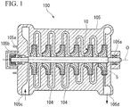
- FIG. 1 is a schematic drawing showing of schematic configuration of a centrifugal compressor 100 having a rotary machine in the present embodiment.
- a rotary shaft 5 is supported pivotally via a journal bearing 105a and a thrust bearing 105b in the casing 105 of the centrifugal compressor 100.
- a plurality of impellers 10 is mounted on the rotary shaft 5 with arranging in a direction of an axis O.
- Each impeller 10 uses a centrifugal force generated by the rotation of the rotation shaft 5, compresses a gas in stages from an upstream side of a flowing-passage 104 formed on the casing 105 toward a downstream side of the flowing-passage 104, and allows the gas to flow.
- an inlet port 105c is formed at one side (left side in FIG. 1 ) in a direction of the axis O of the rotary shaft 5 and is configured to allow the gas to flow-in from the outside
- an outlet port 105d is formed at the other side (right side in FIG. 1 ) in the direction of the axis O and is configured to discharge the gas to the outside. That is, according to the above centrifugal compressor configuration, when the rotation shaft 5 rotates, the gas flows into the flowing passage 104 from the inlet port 105c, the gas is compressed in stages by the impellers 10, and the compressed gas is discharged to the outside from the outlet port 105d.
- FIG. 1 one example providing six impellers 10 on the rotation shaft 5 arranged in series is shown in FIG. 1 .
- at least one impeller 10 may be provided on the rotary shaft 5.
- the following description explains the case where one impeller 10 is provided on the rotary shaft 5 to simplify the description.
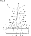
- the impeller 10 of the rotary machine 1 is provided with an inner diameter portion 20, a disk portion 30, a plurality of blade portions 40, and a cover portion 50.
- the inner diameter portion 20 is fitted at the outside of the rotary shaft 5.
- the disk portion 30 is fitted at the outside of the inner diameter portion 20 and having substantially a disk-shape.
- the plurality of blade portions 40 is provided so as to protrude from a surface 31 of the one side in the direction of the axis O of the disk portion 30.
- the cover portion 50 is formed in a single-piece with respect to the blade portions 40, and is formed so as to cover the blade portions 40 from the one side in the direction of the axis O.
- the impeller 10 of the rotary machine 1 is a so-called closed-impeller which includes them.
- the blade portions 40 are formed in a substantially constant thickness and are formed so as to protrude toward the one side in the direction of the axis O from the surface 31 of the one side of the disk portion 30. Furthermore, the blade portions 40 are arranged in a circumferential direction with equal intervals on the surface 31 of the one side of the disk portion 30.
- the blade portion 40 as seen from the direction of the axis O, is formed in a recessed shape so as to have a curve toward a rear direction of the rotation direction (shown in FIG. 2 with an arrow) of the rotation machine 1 and to the outward in a radial direction of the disk portion 30.
- the blade portion 40 has a slightly tapered shape toward outward in the radial direction as seen in a side view.
- the description indicates the case where the blade portion 40 is formed in a curved shape as seen from the direction of the axis O.
- the blade portion 40 may be extended toward the rear side of the rotation direction and to the outward in the radial direction thereof and, for example, the blade portion 40 may be formed straight as seen from the direction of the axis O.
- the inner diameter portion 20 has a substantially cylindrical shape centered at the axis O.
- the inner diameter portion 20 is provided a thin portion 21, a thick portion 22, and an expanding diameter portion 23.
- the thin portion 21 is formed at the one side in the direction of the axis O.
- the thick portion 22 is formed at the other side in the direction of the axis O of the inner diameter portion 20.
- the expanding diameter portion 23 is formed between the thin portion 21 and the thick portion 22, and expands its diameter gradually toward the other side in the direction of the axis O.
- the positioning portion 24 is in contact with a surface 33a of the one side of the fixing portion 33 of the disk portion 30 described as follows, and thereby, the fixing portion 33 of the disk portion 30 restricts displacement toward the one side of the direction of the axis O more than a predetermined fixing position.
- the rigidity of the inner diameter portion 20 at the part in which the positioning portion 24 is formed can be made equivalent to the rigidity of the thick portion 22. Accordingly, the rigidity of the area close to the disk portion 30 of the inner diameter 20 can be uniformized rather than a case where the lightening portion 25 is not formed.
- the thin portion 21 is formed relatively thinner than the above thick portion 22.
- the inner diameter of the thin portion 21 is made slightly smaller than the outer diameter of the rotation shaft 5, and the thin portion 21 is performed a shrink fitting with respect to the rotation shaft 5.
- the shrink fitting at the thin portion 21 the inner diameter portion 20 is fitted with respect to the rotation shaft 5.
- the region A of the shrink fitting is shown with the thick line in FIG. 3 .
- the expanding diameter portion 23 is expanding in diameter toward the other side in the direction of the axis O, and thus, an outer circumferential surface 23a of the expanding diameter portion 23 has a curved shape raising toward the outward in the radial direction of the rotation shaft 5 toward the other side in the direction of the axis O.
- the above described positioning portion 24 is formed by molding having a step toward inner side in the radial direction at the other side in the direction of the axis O of the expanding diameter portion 23.
- the thick portion 22 is formed at the other side in the direction of the axis O than the positioning portion 24.
- the thick portion 22 is formed relatively thicker than the thin portion 21.
- Amounting seating surface 22a is formed substantially in parallel with the outer circumferential surface 5a of the rotation shaft 5 in the outer circumferential surface of the thick portion 22.
- the disk portion 30 is fitted at the outside of this mounting surface 22a.
- the expanding diameter portion 23 and the thick portion 22 are not fitted at the outside of the rotation shaft 5, and thus, the inner diameters of the expanding diameter portion 23 and the thick portion 22 are formed the same as the outer diameter of the rotation shaft 5 or slightly larger than the outer diameter of the rotation shaft 5.
- the disk portion 30 is provided a main body portion 32 and a fixing portion 33.
- the main body portion 32 is arranged at the outward in the radial direction thereof.
- the fixing portion 33 is arranged at the inner side in the radial direction than the main body portion 32.
- the main body portion 32 is formed in a slightly thin plate-shape in the thickness of the outward in the radial direction.
- the thickness in the direction of the axis O of the fixing portion 33 is formed sufficiently larger (for example, approximately twice the length thereof) than the thickness of the base portion side of the above main body portion 32.
- the fixing portion 33 is positioned so as to protrude toward the other side in the direction of the axis O than the position of a surface 32a of the other side of the main body portion 32.
- the thickness in the radial direction of the fixing portion 33 is formed sufficiently thicker than the thickness of the thick portion 22 of the inner diameter portion 20.
- the thickness in the radial direction of the fixing portion 33 is, for example, approximately 2T which is approximately twice the length of the thickness of the thick portion 22.
- the inner circumferential surface 33b of the fixing portion 33 and the mounting seating surface 22a of the thick portion 22 are set approximately same in length in the direction of the axis O.
- the disk portion 30 is formed so that surfaces 32b and 33a of the one side in the direction of the axis O of the main body portion 32 and the fixing portion 33 are in a flat surface.
- the inner diameter of the fixing portion 33 is slightly smaller than the outer diameter of the above described mounting seating surface 22a, and the fixing portion 33 is fitted by shrink fitting with respect to the thick portion 22.
- a surface 50a of the other side in the direction of the axis O of the cover portion 50 is mounted on an edge 40a of the one side of the blade portion 40.
- the thickness of the cover portion 50 is made in a slightly thin plate shape in the thickness of the outward in the radial direction as same as the thickness of the disk portion 30.
- the cover portion 50 is provided with a curved portion 51 which is curved toward the one side in the direction of the axis O in the position of an inner edge 40b of the blade portion 40.
- the expanding diameter portion 23 is arranged at the inner side in the radial direction of the blade portion 40.
- the edge portion 20a of the inner diameter portion 20 is arranged at the one side in the direction of the axis O than an edge surface 51a of the curved portion 51.
- a flow passage 104 which allows the gas to flow is demarcated by the outer circumferential surface 21a of the thin portion 21, the outer circumferential surface 23 a of the expanding diameter portion 23, the surface 30a of the one side of the disk portion 30, the wall surface of the blade portion 40 and the surface 50a of the other side of the cover portion 50.
- the disk portion 30, the blade portion 40 and the cover portion 50 are formed in a single-piece by welding and cutting or the like.
- the inner circumferential surface 33b of the disk portion 30 is fitted by shrink fitting with facing the mounting seating surface 22a of the inner diameter portion 20. Accordingly, the assembling of the impeller 10 is completed.
- the inner diameter portion 20 is fitted by shrink fitting at the predetermined position of the outer circumferential surface 5a of the rotation shaft 5a.
- FIG. 4 shows the case where the conventional impeller 510 is performed shrink fitting
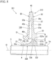
- FIG. 5 shows the case where the impeller 10 in the above described present embodiment is performed shrink fitting
- FIG. 6 shows the changes of the gap size between the disk portions 30, 530 and the inner diameter portions 20, 520 corresponding to each position in the direction of the axis O in FIGS. 4 and 5 .
- the conventional impeller 510 shown in FIG. 4 is different from the impeller 10 of the present embodiment at a point of not providing the fixing portion 33 and the positioning portion 24.
- FIGS. 4 and 5 the position of the impeller before its deformation by the shrink fitting is shown by two-dot chain line in FIGS. 4 and 5 .
- the displacement of each position of the impeller 10 by the shrink fitting is shown in an exaggerated way in FIGS. 4 and 5 , and thus, it is not necessarily corresponding to the gap size shown in FIG. 6 .
- the part of the outer side in the radial direction of the disk portion 530 is pulled toward the one side (left side in FIG. 4 ) in the direction of the axis O by the thermal shrinking of the blade portion 540 and the cover portion 550 and as a result it bends.
- the total rigidity of the blade portion 540 and the cover portion 550 is higher than the rigidity of the disk portion 530 (, and it is the same as in the impeller 10 of the present embodiment).
- the fixing portion 33 of the disk portion 30 is formed so as to protrude to the other side in the direction of the axis O than the main body portion 32, and accordingly, the rigidity of the fixing portion 33 increases.
- the bending of the main body portion 32 is suppressed even though the fixing portion 33 is pulled toward the blade portion 40 and the cover portion 50.
- the rigidity of the fixing portion 33 exceeds the rigidity of the thick portion 22.
- the thick portion 22 deforms to follow the deformation of the fixing portion 33, and therefore, the inner circumferential surface 33b of the fixing portion 33 and the mounting seating surface 22a of the thick portion 22 is maintained in a substantially parallel state. As shown in FIG. 6 , the gap between the inner circumferential surface 33b and the mounting seating surface 22a is hardly occurred in both the bending side c and the opposite side d in the direction of the axis O.
- the fixing portion 33 of the disk portion 30 can be fitted at the outside of the thick portion 22 of the inner diameter portion 20 by the shrink fitting after forming the disk portion 30, the blade portion 40, and the cover portion 50 in a single-piece.
- the space for working at the time of forming in a single-piece the disk portion 30, the blade portion 40, and the cover portion 50 can secure sufficiently.
- the working time can make short and the degree of freedom in design can improve, because the disk portion 30, the blade portion 40, and the cover portion 50 need not necessarily be joined by welding.
- the impeller 10 can easily be assembled with and disassembled from the rotation shaft 5 by applying thermal deformation on the thin portion 21 of the inner diameter portion 20 at the time of maintenance, or the like.
- the disk portion 30 when the disk portion 30 is fitted at the outside of the inner diameter portion 20, even though the disk portion 30 tries to deform toward the one side of the direction of the axis O by being pulled toward the side of the blade portion 40 and the cover portion 50 by the thermal deformation, the disk portion 30 is subjected to constraint of a part of the fixing portion 33 protruded toward the other side in the direction of the axis O than the main body portion 32, and thus, the bending of the disk portion 30 can be reduced. Furthermore, the protruding part of the above fixing portion 33 holds itself in a contacting state so as to contact with the outer circumferential surface of the inner diameter portion 20 without following displacement of the main body portion 32.
- the other side in the direction of the axis O of the fixing portion 33 is prevented from being elevated, and a proper surface pressure can be secured at the fitting surface formed between the inner circumferential surface 33b of the fixing portion 33 and the mounting seating surface 22a of the thick portion 22 to fix the fixing portion 33 to the inner diameter portion 20.
- a proper surface pressure can be secured at the fitting surface formed between the inner circumferential surface 33b of the fixing portion 33 and the mounting seating surface 22a of the thick portion 22 to fix the fixing portion 33 to the inner diameter portion 20.
- the thickness of the fixing portion 33 is set larger than the thickness of the inner diameter portion 20, and accordingly, the inner diameter portion 20 is made thin and made easy to fix on the rotation shaft 5 by the thermal deformation, and the rigidity of the fixing portion 33 can increase. As a result, the deformation of the fixing portion 33 is suppressed and the surface pressure between the inner circumferential surface 33b and the mounting seating surface 22a can be uniformized.
- the disk portion 30 can be positioning accurately with respect to the inner diameter portion 20 when the disk portion 30 is fitted at the outside of the inner diameter portion 20. Therefore, variations of quality, such that steps are formed in the inner surface of the flow passage 104, and the like, can be suppressed.
- the impeller of this second embodiment is provided a recessed portion having an annular shape adjacent to the fixing portion 33 with respect to the impeller 10 of the above described first embodiment.
- the same reference signs are used at the same part of the above described first embodiment.
- the impeller 210 is fitted at the outside of the rotation shaft 5 by the shrink fitting as same as the rotary machine 1 of the above described first embodiment.
- the impeller 210 is provided with an inner diameter portion 20, a disk portion 30, a plurality of blade portions 40, and a cover portion 50.
- the inner diameter portion 20 is fitted at the outside of the rotary shaft 5.
- the disk portion 30 is fitted at the outside of the inner diameter portion 20 and has a disk-shape.
- the blade portions 40 are provided so as to protrude from a surface 30a of the one side in the direction of the axis O of this disk portion 30.
- the cover portion 50 is formed in a single-piece with respect to the blade portions 40, and is formed so as to cover the blade portions 40 from the one side in the direction of the axis O.
- the inner diameter portion 20, the blade portions 40, and a cover portion 50 are configured as the same as the above described first embodiment, and thus, the detail description thereof is omitted.
- the disk portion 30 is provided a main body portion 32 and a fixing portion 33.
- the main body portion 32 is arranged at the outward in the radial direction of the disk portion 30.
- the fixing portion 33 is arranged at the inner side in the radial direction than the main body portion 32.
- a length along the direction of the axis O of the fixing portion 33 is formed sufficiently larger (for example, approximately twice the length thereof) than the length along the direction of the axis O of the base portion side of the main body portion 32 in the radial direction.
- the fixing portion 33 is positioned so as to protrude toward the other side in the direction of the axis O than the position of a surface 32a of the other side of the main body portion 32.
- the thickness in the radial direction of the fixing portion 33 is formed sufficiently thicker than the thickness of the thick portion 22 of the inner diameter portion 20. More specifically, the thickness in the radial direction of the fixing portion 33 is approximately 2T which is approximately twice the length of the thickness of the thick portion 22.
- the inner circumferential surface 33b of the fixing portion 33 and the mounting seating surface 22a of the thick portion 22 are set approximately same in length in the direction of the axis O.
- the disk portion 30 is formed so that surfaces 32b and 33a of the one side in the direction of the axis O of the main body portion 32 and the fixing portion 33 are in a flat surface.
- the inner diameter of the fixing portion 33 is slightly smaller than the outer diameter of the above described mounting seating surface 22a, and the fixing portion 33 is fitted at the outside of the thick portion 22 by the shrink fitting.
- the main body portion 32 is formed in a substantially plate-shape and the thickness thereof becomes slightly thin to the outward in the radial direction.
- a recessed portion 234 having substantially an annular shape around the axis O as a center is formed at the part adjacent to the fixing portion 33 (in other words, the base side of the main body portion 32) at the surface 32a of the other side in the direction of the axis O of the main body portion 32.
- the recessed portion 234 is formed in a square groove shape so as to hollow the surface 32a from the side of the surface 32a of the other side.
- the length along the direction of the axis O of the main body portion 32 is reduced at the amount of the part of which this recessed portion 234 is formed.
- the depth of this recessed portion 234 in the direction of the axis O is preferred to be set as deep as possible in scope of that the strength of the main body portion 32 can be obtained sufficiently.
- the recessed portion 234 may be cut from the other side in the direction of the axis O, but not limited to the above described square groove shape.
- the recessed portion 234 adjacent to the fixing portion 33 and having an annular shape is formed at the surface 32a of the other side in the direction of the axis O of the main body portion 32, and accordingly, a length t2 of which the fixing portion 33 is protruded toward the other side can be relatively longer with respect to a length t1 along the direction of the axis O of the base portion of the main body portion 32 in the inner side of the radial direction of the main body portion 32, without making large the length along the direction of the axis O of the fixing portion 33.
- the impeller 310 in the third embodiment of the present invention and the rotary machine 301 providing the impeller 310 are described.
- the impeller 310 of this third embodiment is different to the impeller 10 in the above described first embodiment at the point of the position of the fixing portion 33 and the shape of the thick portion 22 of the inner diameter portion 20.
- the same reference signs are used at the same part thereof.
- the impeller 310 is fitted at the outside of the rotation shaft 5 by the shrink fitting in the same way as the rotary machine 1 of the above described first embodiment.
- the impeller 310 is provided with an inner diameter portion 320, a disk portion 30, a plurality of blade portions 40, and a cover portion 50.
- the inner diameter portion 320 is fitted at the outside of the rotary shaft 5.
- the disk portion 30 is fitted at the outside of the inner diameter portion 320 and has a substantially disk-shape.
- the blade portions 40 are provided so as to protrude from a surface 30a of the one side in the direction of the axis O of this disk portion 30.
- the cover portion 50 is formed in a single-piece with respect to the blade portions 40, and is formed so as to cover the blade portions 40 from the one side in the direction of the axis O.
- the fixing portion 33 having the same thickness in the radial direction to the thick portion 322 is formed in the disk portion 30.
- the disk portion 30, the blade portions 40, and a cover portion 50 are configured as the same as the above described first embodiment, and thus, the detail description thereof is omitted.
- the inner diameter portion 320 is provided with a thin portion 21 having substantially a cylindrical shape at the one side in the direction of the axis O.
- the inner diameter portion 320 is provided with an expanding diameter portion 23, which gradually expands in diameter toward the other side, at the further other side in the direction of the axis O of the thin portion 21.
- a thick portion 322 having sufficiently larger thickness than the thin portion 21 in the direction of the radial direction is formed at the further other side in the direction of the axis O on the expanding diameter portion 23.
- the thick portion 322 is provided a mounting seating surface 322a formed along the outer circumferential surface of the rotation shaft 5.
- a cut portion 322c which is chamfered is formed between the mounting seating surface 322a and a surface 322b of the other side.
- the length of the mounting seating surface 322a in the direction of the axis O is shorter than an inner circumferential surface 33b of the fixing portion 33 of the disk portion 30.
- the thickness of an edge of the other side in the direction of the axis O of the thick portion 322 is set the same as the thickness 2T of the edge of the other side in the direction of the axis O of the fixing portion 33.
- the disc portion 30 is fitted at the outside of the fixing portion 33 in the state of aligning an edge of the one side in the direction of the axis O with respect to the mounting seating surface 322a of the inner diameter portion 320.
- the chamfer shape of the cut portion 322c has a curved shape, but not limited to this shape.
- FIG. 9A shows the case where the mounting seating surface 322a is extended toward the other side and the above described cut portion 322c is not formed.
- FIG. 9B shows the case where the thick portion 322 is not extended toward the other side than the mounting seating surface 322a.
- the thickness of the thick portion 322 is larger than the thickness of the fixing portion 33 in the radial direction, and thus, the rigidity of the thick portion 322 is substantially constant along the direction of the axis O.
- the deformation mode (the configuration of the deformation), which is occurred by the surface pressure applied from the disk portion 30, becomes to a deformation mode of bending deformation in which a base end of the bending is the thin portion 21 side.
- the thick portion 322 as a whole deforms so as to incline to the inner circumferential side with respect to the axis O toward the other side from the one side in the direction of the axis O of the thick portion 322, and the above gap is created.
- FIGS. 9A and 9B for convenience of description, the displacement of the inner diameter portion 20 is shown in an exaggerated way.
- the thickness of the thick portion 322 in the cut portion 322c is smaller than the thickness of the fixing portion 33. That is, the thick portion 322 has a high rigidity area at the intermediated portion along the direction of the axis O and has low rigidity areas at both sides thereof.
- the deformation mode which is occurred by the surface pressure applied from the disk portion 30, becomes to a deformation mode, which deforms with bending toward the inner circumferential side at both sides of the thin portion 21 side and the cut portion 322c from the intermediated portion in the direction of the axis O.
- the thick portion 322 as a whole does not deform disproportionately so as to incline toward any one of the sides with respect to the axis O.
- the mounting seating surface 322a is held in substantially in parallel with respect to the inner circumferential surface 33b.
- the length in the direction of the axis O of the mounting seating surface 322a of the thick portion 322 is formed smaller than the length in the direction of the axis O of the inner circumferential surface 33b of the fixing portion 33, and thus, even if the inner circumferential surface 33b is bend at the time of the shrink fitting, the mounting seating surface 322a easily fits closely the inner circumferential surface 33b.
- the impeller 310 of the above described third embodiment and the rotary machine 301 even if the thickness in the radial direction of the fixing portion 33 and the thick portion 322 are set to be equivalent, by reducing the rigidity of the thick portion 322 partially by the cutting portion 322c, the mounting seating surface 322a and the inner circumferential surface 33b are kept in substantially parallel and can easily fit closely to each other. Therefore, the surface pressure by the shrink fitting can be sufficiently secured.
- keys or key grooves which form a pair in the inner circumferential surface 33b of the fixing portion 33 and the mounting seating surface 22a, 322a of the thick portion 22, 322 in the above described embodiment and extend to the direction of the axis O, may be formed. According to this configuration, it is possible to perform easily the positioning in a circumferential direction of the impellers 10,210, and 310.
- the degree of freedom in design is improved in the disk portion, the blade portion and the cover portion, and the disk portion, the blade portion and the cover portion can be formed in a single-piece easily.
Landscapes
- Engineering & Computer Science (AREA)
- Mechanical Engineering (AREA)
- General Engineering & Computer Science (AREA)
- Structures Of Non-Positive Displacement Pumps (AREA)
Claims (7)
- Roue comprenant :une portion de diamètre intérieur (20, 320) dont un premier côté dans une direction axiale d'un axe (0) d'un arbre de rotation (5) d'une machine rotative est configuré pour être ajusté à l'extérieur de l'arbre de rotation par déformation thermique ;une portion de disque (30) ajustée à l'extérieur de la portion de diamètre intérieur par déformation thermique sur l'autre côté dans la direction axiale de la portion de diamètre intérieur;une portion d'aube (40) faisant saillie d'une surface de la portion de disque orientée vers le premier côté dans la direction axiale ; etune portion de recouvrement (50) formée d'une seule pièce conjointement avec la portion d'aube et la portion de disque et recouvrant la portion d'aube depuis le premier côté dans la direction axiale :dans laquelle la portion de diamètre intérieur (20, 320) comprend :une portion mince (21) formée sur le premier côté dans la direction de l'axe, et configurée pour être ajustée à l'arbre de rotation par frettage,une portion épaisse (22, 322) formée sur l'autre côté dans la direction de l'axe et ayant une épaisseur supérieure à la portion mince, etune portion à diamètre croissant (23) formée entre la portion mince et la portion épaisse, et ayant un diamètre qui augmente progressivement vers l'autre côté dans la direction de l'axe,dans laquelle les diamètres intérieurs de la portion à diamètre croissant et de la portion épaisse sont formés, lorsque la roue est ajustée sur l'arbre de rotation, de façon à être les mêmes qu'un diamètre extérieur de l'arbre de rotation ou supérieurs au diamètre extérieur de l'arbre de rotation ; etdans laquelle la portion de disque (30) comprend :une portion de corps principal (32) dotée de la portion d'aube, etune portion de fixation (33) disposée sur un côté intérieur de la portion de corps principal dans une direction radiale de l'arbre de rotation et ajustée à l'extérieur d'une surface périphérique extérieure (22a, 322a) de la portion épaisse par frettage,dans laquelle la portion de fixation est formée de façon à faire saillie vers l'autre côté dans la direction axiale depuis une surface (32a) de la portion de corps principal.
- Roue selon la revendication 1, dans laquelle
une épaisseur dans la direction radiale de la portion de fixation (33) est supérieure à celle de la portion de diamètre intérieur (20). - Roue selon la revendication 2, dans laquelle
une portion évidée (234) ayant une forme annulaire est formée adjacente à la portion de fixation (33) sur l'autre côté dans la direction axiale de la portion de corps principal (32). - Roue selon l'une quelconque des revendications 1 à 3, dans laquelle
la portion de diamètre intérieur fournit une portion de positionnement (24) dans la direction axiale de la portion de disque (30). - Roue selon la revendication 4, dans laquelle
la portion de positionnement (24) fournit une portion d'allégement (25) sur une surface de contact (24a) entrant en contact avec une surface (33a) du premier côté dans la direction axiale de la portion de disque (30). - Roue selon la revendication 1, dans laquelle
la portion de diamètre intérieur (20) forme une portion de coupe (322c), qui est chanfreinée, entre l'autre côté dans la direction axiale du diamètre intérieur et la surface périphérique extérieure. - Machine rotative comprenant la roue selon l'une quelconque des revendications 1 à 6.
Applications Claiming Priority (2)
| Application Number | Priority Date | Filing Date | Title |
|---|---|---|---|
| JP2011283953A JP5907723B2 (ja) | 2011-12-26 | 2011-12-26 | 回転機械の製造方法 |
| PCT/JP2012/083427 WO2013099846A1 (fr) | 2011-12-26 | 2012-12-25 | Roue et machine rotative dotée de celle-ci |
Publications (3)
| Publication Number | Publication Date |
|---|---|
| EP2749773A1 EP2749773A1 (fr) | 2014-07-02 |
| EP2749773A4 EP2749773A4 (fr) | 2015-06-17 |
| EP2749773B1 true EP2749773B1 (fr) | 2017-04-05 |
Family
ID=48697331
Family Applications (1)
| Application Number | Title | Priority Date | Filing Date |
|---|---|---|---|
| EP12861319.7A Not-in-force EP2749773B1 (fr) | 2011-12-26 | 2012-12-25 | Roue et machine rotative dotée de celle-ci |
Country Status (5)
| Country | Link |
|---|---|
| US (1) | US9664055B2 (fr) |
| EP (1) | EP2749773B1 (fr) |
| JP (1) | JP5907723B2 (fr) |
| CN (1) | CN103492725B (fr) |
| WO (1) | WO2013099846A1 (fr) |
Families Citing this family (9)
| Publication number | Priority date | Publication date | Assignee | Title |
|---|---|---|---|---|
| US8337979B2 (en) | 2006-05-19 | 2012-12-25 | Massachusetts Institute Of Technology | Nanostructure-reinforced composite articles and methods |
| JP5606358B2 (ja) * | 2011-02-24 | 2014-10-15 | 三菱重工業株式会社 | インペラ及びこれを備えたロータ並びにインペラの製造方法 |
| JP2013047479A (ja) | 2011-08-29 | 2013-03-07 | Mitsubishi Heavy Ind Ltd | インペラ及びこれを備えた回転機械並びにインペラの製造方法 |
| JP5967966B2 (ja) * | 2012-02-13 | 2016-08-10 | 三菱重工コンプレッサ株式会社 | インペラ及びこれを備えた回転機械 |
| JP6327505B2 (ja) | 2013-11-21 | 2018-05-23 | 三菱重工業株式会社 | インペラ及び回転機械 |
| US10982548B2 (en) | 2017-02-20 | 2021-04-20 | Mitsubishi Heavy Industries Compressor Corporation | Impeller, rotary machine, method for manufacturing impeller, and method for manufacturing rotary machine |
| KR20200047571A (ko) * | 2017-08-24 | 2020-05-07 | 지이 르네와블 (스위처랜드) 게엠베하 | 팬 |
| RU187330U1 (ru) * | 2018-11-06 | 2019-03-01 | Владимир Васильевич Галайко | Рабочее колесо центробежного насоса |
| JP7588975B2 (ja) | 2020-06-30 | 2024-11-25 | 三菱重工コンプレッサ株式会社 | 回転機械のインペラ及び回転機械 |
Family Cites Families (48)
| Publication number | Priority date | Publication date | Assignee | Title |
|---|---|---|---|---|
| DE755198C (de) * | 1935-12-20 | 1952-11-24 | Versuchsanstalt Fuer Luftfahrt | Kreiselradmaschinenlaufrad fuer hohe Umfangsgeschwindigkeiten |
| US2613609A (en) * | 1942-01-28 | 1952-10-14 | Buchi Alfred | Compressing machine such as centrifugal blower or pump |
| US2438866A (en) | 1945-06-01 | 1948-03-30 | United Aircraft Corp | Impeller mounting |
| US2799445A (en) | 1955-12-12 | 1957-07-16 | Gen Electric | High speed rotor |
| FR1471604A (fr) | 1966-03-10 | 1967-03-03 | Neu Sa | Perfectionnement à la construction de roues fermées de compresseurs centrifuges en alliage léger |
| DE2621201C3 (de) | 1976-05-13 | 1979-09-27 | Maschinenfabrik Augsburg-Nuernberg Ag, 8900 Augsburg | Laufrad für eine Strömungsmaschine |
| US4231706A (en) | 1977-04-27 | 1980-11-04 | Hitachi, Ltd. | Impeller of a centrifugal blower |
| US4173429A (en) | 1977-12-05 | 1979-11-06 | Westinghouse Electric Corp. | Centrifugal fan, shaft, plate and hub assembly |
| CA1131247A (fr) | 1978-06-12 | 1982-09-07 | Burton Brooks | Sulfonation d'hydrocarbures aromatiques alkyles |
| JPS554376U (fr) * | 1978-06-26 | 1980-01-12 | ||
| JPS555456A (en) | 1978-06-28 | 1980-01-16 | Hitachi Ltd | No-hub pump |
| US4220372A (en) | 1978-11-06 | 1980-09-02 | Allis-Chalmers Corporation | Dual wheel and axle assembly |
| JPS5872491A (ja) | 1981-10-28 | 1983-04-30 | Hitachi Ltd | 印字圧調整機構 |
| JPS5872491U (ja) * | 1981-11-11 | 1983-05-17 | 株式会社日立製作所 | 遠心ポンプの羽根車 |
| US4602411A (en) | 1984-01-13 | 1986-07-29 | Westinghouse Electric Corp. | Method for fabricating a rotor disc assembly |
| JPS61142393A (ja) * | 1984-12-17 | 1986-06-30 | Mitsubishi Heavy Ind Ltd | 耐摩耗インペラ |
| JPS61212601A (ja) * | 1985-03-18 | 1986-09-20 | Mitsubishi Heavy Ind Ltd | 回転機の羽根車の取付構造 |
| JPH0417762Y2 (fr) | 1985-06-19 | 1992-04-21 | ||
| SU1373883A1 (ru) | 1986-01-17 | 1988-02-15 | Производственное объединение "Невский завод" им.В.И.Ленина | Рабочее колесо центробежного компрессора |
| DE3709518C2 (de) * | 1987-03-23 | 1995-01-19 | Hilge Philipp Gmbh | Laufrad |
| EP0379197B1 (fr) * | 1989-01-19 | 1993-12-08 | Ebara Corporation | Impulseur de pompe |
| CN2069501U (zh) * | 1990-04-29 | 1991-01-16 | 重庆钢都机修厂 | 大型离心式风机用叶轮 |
| JP2730268B2 (ja) | 1990-05-25 | 1998-03-25 | ダイキン工業株式会社 | 遠心式羽根車 |
| JP2788818B2 (ja) | 1992-03-31 | 1998-08-20 | シャープ株式会社 | アクティブマトリクス入出力装置 |
| DE4427115C1 (de) | 1994-07-30 | 1995-04-06 | Braun Ag | Laufrad für ein Radialgebläse |
| CN1160516C (zh) | 1998-05-13 | 2004-08-04 | 松下电器产业株式会社 | 电动送风机及采用它的电动吸尘器 |
| JP2001355595A (ja) | 2000-06-13 | 2001-12-26 | Hitachi Ltd | ポンプ用羽根車の製造方法及び該羽根車を用いて成るポンプ |
| US6481970B2 (en) | 2000-06-28 | 2002-11-19 | Honeywell International Inc. | Compressor wheel with prestressed hub and interference fit insert |
| IT1319495B1 (it) | 2000-11-30 | 2003-10-20 | Nuovo Pignone Spa | Procedimento per la realizzazione di un rotore per compressoricentrifughi. |
| JP2003293988A (ja) * | 2002-04-01 | 2003-10-15 | Mitsubishi Heavy Ind Ltd | 多段ロータ及びこれを備えた遠心圧縮機 |
| JP2004036444A (ja) | 2002-07-02 | 2004-02-05 | Ishikawajima Harima Heavy Ind Co Ltd | シュラウド付インペラーの製造方法 |
| JP2004060460A (ja) | 2002-07-25 | 2004-02-26 | Mitsubishi Heavy Ind Ltd | 圧縮機のインペラとインペラの取付方法 |
| ITMI20021876A1 (it) | 2002-09-03 | 2004-03-04 | Nuovo Pignone Spa | Procedimento migliorato per realizzare un rotore di un |
| JP4428044B2 (ja) | 2003-03-24 | 2010-03-10 | 株式会社日立プラントテクノロジー | 羽根車の製作方法、及び羽根車 |
| CN2763589Y (zh) | 2004-12-14 | 2006-03-08 | 上海连成(集团)有限公司 | 一种用于高温高压泵的新型转子 |
| US7341430B2 (en) | 2004-12-28 | 2008-03-11 | Nissan Motor Co., Ltd. | Vane wheel for torque converter and manufacturing method |
| US7632073B2 (en) | 2005-06-08 | 2009-12-15 | Dresser-Rand Company | Impeller with machining access panel |
| JP4935435B2 (ja) | 2007-03-09 | 2012-05-23 | トヨタ自動車株式会社 | ガスタービンの焼ばめ締結構造 |
| JP2009156122A (ja) | 2007-12-26 | 2009-07-16 | Mitsubishi Heavy Ind Ltd | 遠心圧縮機用インペラ |
| CN101255871A (zh) | 2008-01-22 | 2008-09-03 | 上海东方泵业(集团)有限公司 | 一种水泵叶轮的加工方法 |
| EP2143957B2 (fr) | 2008-07-10 | 2016-08-10 | Grundfos Management A/S | Composant d'écoulement d'une pompe |
| JP2010121612A (ja) | 2008-10-23 | 2010-06-03 | Mitsubishi Heavy Ind Ltd | インペラ、圧縮機およびインペラの製造方法 |
| JP4699531B2 (ja) | 2009-01-27 | 2011-06-15 | 三菱重工業株式会社 | インペラの製造方法およびインペラ |
| JP5107306B2 (ja) | 2009-06-10 | 2012-12-26 | 三菱重工業株式会社 | 遠心回転機のインペラの製造方法及び遠心回転機のインペラ |
| DE102009031737A1 (de) | 2009-07-04 | 2011-07-21 | MAN Diesel & Turbo SE, 86153 | Laufrad für eine Turbomaschine |
| JP5606358B2 (ja) | 2011-02-24 | 2014-10-15 | 三菱重工業株式会社 | インペラ及びこれを備えたロータ並びにインペラの製造方法 |
| JP5777529B2 (ja) | 2012-01-05 | 2015-09-09 | 三菱重工業株式会社 | インペラ及びこれを備えたロータ並びにインペラの製造方法 |
| CN205117803U (zh) | 2015-11-20 | 2016-03-30 | 湖北双剑鼓风机股份有限公司 | 一种单极煤气离心鼓风机防泄漏轮毂 |
-
2011
- 2011-12-26 JP JP2011283953A patent/JP5907723B2/ja not_active Expired - Fee Related
-
2012
- 2012-12-25 EP EP12861319.7A patent/EP2749773B1/fr not_active Not-in-force
- 2012-12-25 US US14/114,584 patent/US9664055B2/en not_active Expired - Fee Related
- 2012-12-25 CN CN201280019373.2A patent/CN103492725B/zh not_active Expired - Fee Related
- 2012-12-25 WO PCT/JP2012/083427 patent/WO2013099846A1/fr not_active Ceased
Also Published As
| Publication number | Publication date |
|---|---|
| JP5907723B2 (ja) | 2016-04-26 |
| JP2013133735A (ja) | 2013-07-08 |
| CN103492725B (zh) | 2016-01-27 |
| CN103492725A (zh) | 2014-01-01 |
| US9664055B2 (en) | 2017-05-30 |
| WO2013099846A1 (fr) | 2013-07-04 |
| EP2749773A4 (fr) | 2015-06-17 |
| US20140064975A1 (en) | 2014-03-06 |
| EP2749773A1 (fr) | 2014-07-02 |
Similar Documents
| Publication | Publication Date | Title |
|---|---|---|
| EP2749773B1 (fr) | Roue et machine rotative dotée de celle-ci | |
| JP4275081B2 (ja) | 可変容量型排気ターボ過給機のスクロール構造及びその製造方法 | |
| US9903385B2 (en) | Impeller, rotary machine including the same, and method for manufacturing impeller | |
| JP6208141B2 (ja) | ロータ、及び、このロータを備えた真空ポンプ | |
| JP2007255420A (ja) | 回転機械用インペラおよびインペラの製造方法 | |
| US10443605B2 (en) | Impeller, rotary machine, and impeller manufacturing method | |
| WO2017109995A1 (fr) | Mécanisme à buse variable et turbocompresseur à géométrie variable | |
| KR101745098B1 (ko) | 압축기 및 압축기의 제조 방법 | |
| JP6589217B2 (ja) | 回転機械、回転機械の製造方法 | |
| EP3173599B1 (fr) | Mécanisme à buse variable et turbocompresseur à déplacement variable | |
| JP2019044736A (ja) | 多段遠心流体機械 | |
| CN110418897B (zh) | 旋转体、增压器以及旋转体的制造方法 | |
| EP3557076B1 (fr) | Turbine, machine rotative, procédé de fabrication de turbine et procédé de fabrication de machine rotative | |
| WO2020012731A1 (fr) | Compresseur de suralimentation | |
| JP2007291862A (ja) | 両吸込渦巻ポンプおよびその羽根車並びに羽根車の製造方法 | |
| JP5811593B2 (ja) | ガイドベーンユニットの軸受構造、及び過給機 | |
| JP7831149B2 (ja) | 回転機械 | |
| JP7531455B2 (ja) | ポンプ装置 | |
| JP2010196680A (ja) | 両吸込ポンプ | |
| JP2020037900A (ja) | 遠心羽根車および遠心式流体機械 | |
| CN105840525A (zh) | 定子盘 | |
| JP2012219631A (ja) | ターボ分子ポンプ |
Legal Events
| Date | Code | Title | Description |
|---|---|---|---|
| PUAI | Public reference made under article 153(3) epc to a published international application that has entered the european phase |
Free format text: ORIGINAL CODE: 0009012 |
|
| 17P | Request for examination filed |
Effective date: 20131113 |
|
| AK | Designated contracting states |
Kind code of ref document: A1 Designated state(s): AL AT BE BG CH CY CZ DE DK EE ES FI FR GB GR HR HU IE IS IT LI LT LU LV MC MK MT NL NO PL PT RO RS SE SI SK SM TR |
|
| DAX | Request for extension of the european patent (deleted) | ||
| REG | Reference to a national code |
Ref country code: DE Ref legal event code: R079 Ref document number: 602012030915 Country of ref document: DE Free format text: PREVIOUS MAIN CLASS: F04D0029280000 Ipc: F01D0005300000 |
|
| RA4 | Supplementary search report drawn up and despatched (corrected) |
Effective date: 20150518 |
|
| RIC1 | Information provided on ipc code assigned before grant |
Ipc: F04D 29/62 20060101ALI20150511BHEP Ipc: F04D 29/26 20060101ALI20150511BHEP Ipc: F01D 5/30 20060101AFI20150511BHEP Ipc: F04D 29/28 20060101ALI20150511BHEP |
|
| GRAP | Despatch of communication of intention to grant a patent |
Free format text: ORIGINAL CODE: EPIDOSNIGR1 |
|
| INTG | Intention to grant announced |
Effective date: 20161031 |
|
| GRAS | Grant fee paid |
Free format text: ORIGINAL CODE: EPIDOSNIGR3 |
|
| GRAA | (expected) grant |
Free format text: ORIGINAL CODE: 0009210 |
|
| AK | Designated contracting states |
Kind code of ref document: B1 Designated state(s): AL AT BE BG CH CY CZ DE DK EE ES FI FR GB GR HR HU IE IS IT LI LT LU LV MC MK MT NL NO PL PT RO RS SE SI SK SM TR |
|
| REG | Reference to a national code |
Ref country code: GB Ref legal event code: FG4D |
|
| REG | Reference to a national code |
Ref country code: CH Ref legal event code: EP |
|
| REG | Reference to a national code |
Ref country code: AT Ref legal event code: REF Ref document number: 882031 Country of ref document: AT Kind code of ref document: T Effective date: 20170415 |
|
| REG | Reference to a national code |
Ref country code: IE Ref legal event code: FG4D |
|
| REG | Reference to a national code |
Ref country code: DE Ref legal event code: R096 Ref document number: 602012030915 Country of ref document: DE |
|
| REG | Reference to a national code |
Ref country code: NL Ref legal event code: MP Effective date: 20170405 |
|
| REG | Reference to a national code |
Ref country code: LT Ref legal event code: MG4D |
|
| REG | Reference to a national code |
Ref country code: AT Ref legal event code: MK05 Ref document number: 882031 Country of ref document: AT Kind code of ref document: T Effective date: 20170405 |
|
| PG25 | Lapsed in a contracting state [announced via postgrant information from national office to epo] |
Ref country code: NL Free format text: LAPSE BECAUSE OF FAILURE TO SUBMIT A TRANSLATION OF THE DESCRIPTION OR TO PAY THE FEE WITHIN THE PRESCRIBED TIME-LIMIT Effective date: 20170405 |
|
| PG25 | Lapsed in a contracting state [announced via postgrant information from national office to epo] |
Ref country code: HR Free format text: LAPSE BECAUSE OF FAILURE TO SUBMIT A TRANSLATION OF THE DESCRIPTION OR TO PAY THE FEE WITHIN THE PRESCRIBED TIME-LIMIT Effective date: 20170405 Ref country code: LT Free format text: LAPSE BECAUSE OF FAILURE TO SUBMIT A TRANSLATION OF THE DESCRIPTION OR TO PAY THE FEE WITHIN THE PRESCRIBED TIME-LIMIT Effective date: 20170405 Ref country code: FI Free format text: LAPSE BECAUSE OF FAILURE TO SUBMIT A TRANSLATION OF THE DESCRIPTION OR TO PAY THE FEE WITHIN THE PRESCRIBED TIME-LIMIT Effective date: 20170405 Ref country code: GR Free format text: LAPSE BECAUSE OF FAILURE TO SUBMIT A TRANSLATION OF THE DESCRIPTION OR TO PAY THE FEE WITHIN THE PRESCRIBED TIME-LIMIT Effective date: 20170706 Ref country code: AT Free format text: LAPSE BECAUSE OF FAILURE TO SUBMIT A TRANSLATION OF THE DESCRIPTION OR TO PAY THE FEE WITHIN THE PRESCRIBED TIME-LIMIT Effective date: 20170405 Ref country code: ES Free format text: LAPSE BECAUSE OF FAILURE TO SUBMIT A TRANSLATION OF THE DESCRIPTION OR TO PAY THE FEE WITHIN THE PRESCRIBED TIME-LIMIT Effective date: 20170405 Ref country code: NO Free format text: LAPSE BECAUSE OF FAILURE TO SUBMIT A TRANSLATION OF THE DESCRIPTION OR TO PAY THE FEE WITHIN THE PRESCRIBED TIME-LIMIT Effective date: 20170705 |
|
| PG25 | Lapsed in a contracting state [announced via postgrant information from national office to epo] |
Ref country code: IS Free format text: LAPSE BECAUSE OF FAILURE TO SUBMIT A TRANSLATION OF THE DESCRIPTION OR TO PAY THE FEE WITHIN THE PRESCRIBED TIME-LIMIT Effective date: 20170805 Ref country code: SE Free format text: LAPSE BECAUSE OF FAILURE TO SUBMIT A TRANSLATION OF THE DESCRIPTION OR TO PAY THE FEE WITHIN THE PRESCRIBED TIME-LIMIT Effective date: 20170405 Ref country code: LV Free format text: LAPSE BECAUSE OF FAILURE TO SUBMIT A TRANSLATION OF THE DESCRIPTION OR TO PAY THE FEE WITHIN THE PRESCRIBED TIME-LIMIT Effective date: 20170405 Ref country code: PL Free format text: LAPSE BECAUSE OF FAILURE TO SUBMIT A TRANSLATION OF THE DESCRIPTION OR TO PAY THE FEE WITHIN THE PRESCRIBED TIME-LIMIT Effective date: 20170405 Ref country code: BG Free format text: LAPSE BECAUSE OF FAILURE TO SUBMIT A TRANSLATION OF THE DESCRIPTION OR TO PAY THE FEE WITHIN THE PRESCRIBED TIME-LIMIT Effective date: 20170705 Ref country code: RS Free format text: LAPSE BECAUSE OF FAILURE TO SUBMIT A TRANSLATION OF THE DESCRIPTION OR TO PAY THE FEE WITHIN THE PRESCRIBED TIME-LIMIT Effective date: 20170405 |
|
| REG | Reference to a national code |
Ref country code: FR Ref legal event code: PLFP Year of fee payment: 6 |
|
| REG | Reference to a national code |
Ref country code: DE Ref legal event code: R097 Ref document number: 602012030915 Country of ref document: DE |
|
| PG25 | Lapsed in a contracting state [announced via postgrant information from national office to epo] |
Ref country code: EE Free format text: LAPSE BECAUSE OF FAILURE TO SUBMIT A TRANSLATION OF THE DESCRIPTION OR TO PAY THE FEE WITHIN THE PRESCRIBED TIME-LIMIT Effective date: 20170405 Ref country code: DK Free format text: LAPSE BECAUSE OF FAILURE TO SUBMIT A TRANSLATION OF THE DESCRIPTION OR TO PAY THE FEE WITHIN THE PRESCRIBED TIME-LIMIT Effective date: 20170405 Ref country code: RO Free format text: LAPSE BECAUSE OF FAILURE TO SUBMIT A TRANSLATION OF THE DESCRIPTION OR TO PAY THE FEE WITHIN THE PRESCRIBED TIME-LIMIT Effective date: 20170405 Ref country code: CZ Free format text: LAPSE BECAUSE OF FAILURE TO SUBMIT A TRANSLATION OF THE DESCRIPTION OR TO PAY THE FEE WITHIN THE PRESCRIBED TIME-LIMIT Effective date: 20170405 Ref country code: SK Free format text: LAPSE BECAUSE OF FAILURE TO SUBMIT A TRANSLATION OF THE DESCRIPTION OR TO PAY THE FEE WITHIN THE PRESCRIBED TIME-LIMIT Effective date: 20170405 |
|
| PGFP | Annual fee paid to national office [announced via postgrant information from national office to epo] |
Ref country code: FR Payment date: 20171220 Year of fee payment: 6 |
|
| PLBE | No opposition filed within time limit |
Free format text: ORIGINAL CODE: 0009261 |
|
| STAA | Information on the status of an ep patent application or granted ep patent |
Free format text: STATUS: NO OPPOSITION FILED WITHIN TIME LIMIT |
|
| PG25 | Lapsed in a contracting state [announced via postgrant information from national office to epo] |
Ref country code: SM Free format text: LAPSE BECAUSE OF FAILURE TO SUBMIT A TRANSLATION OF THE DESCRIPTION OR TO PAY THE FEE WITHIN THE PRESCRIBED TIME-LIMIT Effective date: 20170405 |
|
| 26N | No opposition filed |
Effective date: 20180108 |
|
| PGFP | Annual fee paid to national office [announced via postgrant information from national office to epo] |
Ref country code: DE Payment date: 20171222 Year of fee payment: 6 |
|
| PG25 | Lapsed in a contracting state [announced via postgrant information from national office to epo] |
Ref country code: SI Free format text: LAPSE BECAUSE OF FAILURE TO SUBMIT A TRANSLATION OF THE DESCRIPTION OR TO PAY THE FEE WITHIN THE PRESCRIBED TIME-LIMIT Effective date: 20170405 |
|
| PGFP | Annual fee paid to national office [announced via postgrant information from national office to epo] |
Ref country code: IT Payment date: 20171222 Year of fee payment: 6 |
|
| REG | Reference to a national code |
Ref country code: CH Ref legal event code: PL |
|
| GBPC | Gb: european patent ceased through non-payment of renewal fee |
Effective date: 20171225 |
|
| REG | Reference to a national code |
Ref country code: IE Ref legal event code: MM4A |
|
| PG25 | Lapsed in a contracting state [announced via postgrant information from national office to epo] |
Ref country code: LU Free format text: LAPSE BECAUSE OF NON-PAYMENT OF DUE FEES Effective date: 20171225 Ref country code: MT Free format text: LAPSE BECAUSE OF NON-PAYMENT OF DUE FEES Effective date: 20171225 |
|
| REG | Reference to a national code |
Ref country code: BE Ref legal event code: MM Effective date: 20171231 |
|
| PG25 | Lapsed in a contracting state [announced via postgrant information from national office to epo] |
Ref country code: IE Free format text: LAPSE BECAUSE OF NON-PAYMENT OF DUE FEES Effective date: 20171225 |
|
| PG25 | Lapsed in a contracting state [announced via postgrant information from national office to epo] |
Ref country code: CH Free format text: LAPSE BECAUSE OF NON-PAYMENT OF DUE FEES Effective date: 20171231 Ref country code: LI Free format text: LAPSE BECAUSE OF NON-PAYMENT OF DUE FEES Effective date: 20171231 Ref country code: BE Free format text: LAPSE BECAUSE OF NON-PAYMENT OF DUE FEES Effective date: 20171231 Ref country code: GB Free format text: LAPSE BECAUSE OF NON-PAYMENT OF DUE FEES Effective date: 20171225 |
|
| PG25 | Lapsed in a contracting state [announced via postgrant information from national office to epo] |
Ref country code: MC Free format text: LAPSE BECAUSE OF FAILURE TO SUBMIT A TRANSLATION OF THE DESCRIPTION OR TO PAY THE FEE WITHIN THE PRESCRIBED TIME-LIMIT Effective date: 20170405 Ref country code: HU Free format text: LAPSE BECAUSE OF FAILURE TO SUBMIT A TRANSLATION OF THE DESCRIPTION OR TO PAY THE FEE WITHIN THE PRESCRIBED TIME-LIMIT; INVALID AB INITIO Effective date: 20121225 |
|
| REG | Reference to a national code |
Ref country code: DE Ref legal event code: R119 Ref document number: 602012030915 Country of ref document: DE |
|
| PG25 | Lapsed in a contracting state [announced via postgrant information from national office to epo] |
Ref country code: CY Free format text: LAPSE BECAUSE OF NON-PAYMENT OF DUE FEES Effective date: 20170405 Ref country code: IT Free format text: LAPSE BECAUSE OF NON-PAYMENT OF DUE FEES Effective date: 20181225 Ref country code: FR Free format text: LAPSE BECAUSE OF NON-PAYMENT OF DUE FEES Effective date: 20181231 Ref country code: DE Free format text: LAPSE BECAUSE OF NON-PAYMENT OF DUE FEES Effective date: 20190702 |
|
| PG25 | Lapsed in a contracting state [announced via postgrant information from national office to epo] |
Ref country code: MK Free format text: LAPSE BECAUSE OF FAILURE TO SUBMIT A TRANSLATION OF THE DESCRIPTION OR TO PAY THE FEE WITHIN THE PRESCRIBED TIME-LIMIT Effective date: 20170405 |
|
| PG25 | Lapsed in a contracting state [announced via postgrant information from national office to epo] |
Ref country code: TR Free format text: LAPSE BECAUSE OF FAILURE TO SUBMIT A TRANSLATION OF THE DESCRIPTION OR TO PAY THE FEE WITHIN THE PRESCRIBED TIME-LIMIT Effective date: 20170405 |
|
| PG25 | Lapsed in a contracting state [announced via postgrant information from national office to epo] |
Ref country code: PT Free format text: LAPSE BECAUSE OF FAILURE TO SUBMIT A TRANSLATION OF THE DESCRIPTION OR TO PAY THE FEE WITHIN THE PRESCRIBED TIME-LIMIT Effective date: 20170405 |
|
| PG25 | Lapsed in a contracting state [announced via postgrant information from national office to epo] |
Ref country code: AL Free format text: LAPSE BECAUSE OF FAILURE TO SUBMIT A TRANSLATION OF THE DESCRIPTION OR TO PAY THE FEE WITHIN THE PRESCRIBED TIME-LIMIT Effective date: 20170405 |