EP2749788A2 - Zweimassenschwungrad - Google Patents
Zweimassenschwungrad Download PDFInfo
- Publication number
- EP2749788A2 EP2749788A2 EP13193582.7A EP13193582A EP2749788A2 EP 2749788 A2 EP2749788 A2 EP 2749788A2 EP 13193582 A EP13193582 A EP 13193582A EP 2749788 A2 EP2749788 A2 EP 2749788A2
- Authority
- EP
- European Patent Office
- Prior art keywords
- spring
- flywheel
- guide
- primary
- drive units
- Prior art date
- Legal status (The legal status is an assumption and is not a legal conclusion. Google has not performed a legal analysis and makes no representation as to the accuracy of the status listed.)
- Withdrawn
Links
- 230000009977 dual effect Effects 0.000 title claims abstract description 40
- 230000008878 coupling Effects 0.000 claims abstract description 14
- 238000010168 coupling process Methods 0.000 claims abstract description 14
- 238000005859 coupling reaction Methods 0.000 claims abstract description 14
- 230000005540 biological transmission Effects 0.000 claims abstract description 11
- 230000002265 prevention Effects 0.000 claims abstract description 9
- 238000000926 separation method Methods 0.000 claims abstract description 9
- 238000000034 method Methods 0.000 description 10
- 239000004519 grease Substances 0.000 description 4
- 230000003247 decreasing effect Effects 0.000 description 2
- 238000010586 diagram Methods 0.000 description 2
- 230000001133 acceleration Effects 0.000 description 1
- 230000000694 effects Effects 0.000 description 1
- 239000000314 lubricant Substances 0.000 description 1
- 238000005461 lubrication Methods 0.000 description 1
- 238000007789 sealing Methods 0.000 description 1
Images


Classifications
-
- F—MECHANICAL ENGINEERING; LIGHTING; HEATING; WEAPONS; BLASTING
- F16—ENGINEERING ELEMENTS AND UNITS; GENERAL MEASURES FOR PRODUCING AND MAINTAINING EFFECTIVE FUNCTIONING OF MACHINES OR INSTALLATIONS; THERMAL INSULATION IN GENERAL
- F16F—SPRINGS; SHOCK-ABSORBERS; MEANS FOR DAMPING VIBRATION
- F16F15/00—Suppression of vibrations in systems; Means or arrangements for avoiding or reducing out-of-balance forces, e.g. due to motion
- F16F15/30—Flywheels
-
- F—MECHANICAL ENGINEERING; LIGHTING; HEATING; WEAPONS; BLASTING
- F16—ENGINEERING ELEMENTS AND UNITS; GENERAL MEASURES FOR PRODUCING AND MAINTAINING EFFECTIVE FUNCTIONING OF MACHINES OR INSTALLATIONS; THERMAL INSULATION IN GENERAL
- F16F—SPRINGS; SHOCK-ABSORBERS; MEANS FOR DAMPING VIBRATION
- F16F15/00—Suppression of vibrations in systems; Means or arrangements for avoiding or reducing out-of-balance forces, e.g. due to motion
- F16F15/10—Suppression of vibrations in rotating systems by making use of members moving with the system
- F16F15/12—Suppression of vibrations in rotating systems by making use of members moving with the system using elastic members or friction-damping members, e.g. between a rotating shaft and a gyratory mass mounted thereon
- F16F15/131—Suppression of vibrations in rotating systems by making use of members moving with the system using elastic members or friction-damping members, e.g. between a rotating shaft and a gyratory mass mounted thereon the rotating system comprising two or more gyratory masses
- F16F15/133—Suppression of vibrations in rotating systems by making use of members moving with the system using elastic members or friction-damping members, e.g. between a rotating shaft and a gyratory mass mounted thereon the rotating system comprising two or more gyratory masses using springs as elastic members, e.g. metallic springs
- F16F15/134—Wound springs
- F16F15/1343—Wound springs characterised by the spring mounting
- F16F15/13453—Additional guiding means for springs
-
- F—MECHANICAL ENGINEERING; LIGHTING; HEATING; WEAPONS; BLASTING
- F16—ENGINEERING ELEMENTS AND UNITS; GENERAL MEASURES FOR PRODUCING AND MAINTAINING EFFECTIVE FUNCTIONING OF MACHINES OR INSTALLATIONS; THERMAL INSULATION IN GENERAL
- F16F—SPRINGS; SHOCK-ABSORBERS; MEANS FOR DAMPING VIBRATION
- F16F15/00—Suppression of vibrations in systems; Means or arrangements for avoiding or reducing out-of-balance forces, e.g. due to motion
- F16F15/30—Flywheels
- F16F15/31—Flywheels characterised by means for varying the moment of inertia
-
- Y—GENERAL TAGGING OF NEW TECHNOLOGICAL DEVELOPMENTS; GENERAL TAGGING OF CROSS-SECTIONAL TECHNOLOGIES SPANNING OVER SEVERAL SECTIONS OF THE IPC; TECHNICAL SUBJECTS COVERED BY FORMER USPC CROSS-REFERENCE ART COLLECTIONS [XRACs] AND DIGESTS
- Y10—TECHNICAL SUBJECTS COVERED BY FORMER USPC
- Y10T—TECHNICAL SUBJECTS COVERED BY FORMER US CLASSIFICATION
- Y10T74/00—Machine element or mechanism
- Y10T74/21—Elements
- Y10T74/2121—Flywheel, motion smoothing-type
- Y10T74/2132—Structural detail, e.g., fiber, held by magnet, etc.
Definitions
- the present invention relates to a dual mass flywheel, and more particularly to an improved dual mass flywheel which effectively mitigates an impact and noise generated while causing no loss of torque in a process of transferring power of an engine to a transmission and has a simpler configuration due to a decreased number of components.
- a dual mass flywheel (DMF) for a vehicle is adapted to mitigate an impact between an engine and a transmission due to a dampening operation of an arc spring while a driving plate connecting a primary flywheel and a secondary flywheel are moved in conjunction with an arc spring mounted to the primary mass, thereby reducing vibrations and noise due to an abrupt acceleration of a vehicle such as gear noise and body booming.
- the dual mass flywheel 1 includes a primary flywheel 3 having a ring gear 2 and coupled to an output shaft of an engine, a secondary flywheel 4 connected to an input shaft of a transmission, and a coupling element 5 as a unit for coupling the primary flywheel 3 and the secondary flywheel 4.
- the drive units 8 are accommodated in a unit groove Q integrally formed in the primary flywheel 3, and driving pins 10 protruding from a bottom surface of the secondary flywheel 4 are located in operation slots 11 formed in the unit groove Q to press the drive units 8.
- the dual mass flywheel according to the related art uses a principle of generating a torque by an operation angle formed by circumferentially moving a spring with a driving plate, and thus since a force of deviating the spring to an outer circumferential side in the process of circumferentially compressing or expanding the spring is strongly applied, the spring guides accommodating and guiding the spring receives the force, generating friction with the unit groove.
- Grease is applied to the spring or the spring guides holding the spring to reduce frictional resistance while reducing the joint, in which case grease may be leaked in the operation process to disturb normal operation of another component, and when a sealing unit for preventing leakage of grease, the number of components is increased.
- the spring guides make severe contacts with an inner wall of the unit groove. Further, since the spring guides are accommodated in the unit groove, a length of an outer circumference to which a force is transferred is longer than a length of an inner circumference thereof, making frictional resistance more severe.
- the spring maintained by the spring guides uses only a linear coil spring, various noises and vibrations cannot be absorbed and the spring guides surround an outer side of the spring, the spring cannot be stably and firmly maintained.
- an object of the present invention is to provide an improved dual mass flywheel which effectively mitigates an impact and noise generated while causing no loss of torque in a process of transferring power of an engine to a transmission and has a simpler configuration due to a decreased number of components.
- a dual mass flywheel including: a primary flywheel having a ring gear and connected to an output shaft of an engine; a secondary flywheel connected to an input shaft of a transmission; a coupling unit for coupling the primary flywheel and the secondary flywheel; a plurality of drive units coupled to the primary flywheel and the secondary flywheel and in which spring guides are coupled to opposite sides of a torsion spring to dampen noise and vibrations while a torque of the primary flywheel is transferred to the secondary flywheel; a unit groove formed in the primary flywheel to accommodate the drive units; separation prevention bosses formed above and below a center line of the unit groove and having an operation slot therebetween to prevent deviation of the drive units; and driving pins protruding from a bottom surface of the secondary flywheel to compress and damp the drive units, wherein a linear spring and a curved spring of a torsion spring are combined between an end guide and a middle guide or between the middle guides to prevent a contacting point thereof from being pushed to the outside
- a dual mass flywheel comprising: a primary flywheel having a ring gear and connected to an output shaft of an engine; a secondary flywheel connected to an input shaft of a transmission; a coupling unit for coupling the primary flywheel and the secondary flywheel; a plurality of drive units in which spring guides are coupled to opposite sides of a torsion spring arranged to dampen noise or vibration while a torque of the primary flywheel is transferred to the secondary flywheel; a unit groove formed in the primary flywheel, arranged to accommodate the drive units; separation prevention bosses having an operation slot therebetween, formed to prevent deviation of the drive units; and driving pins protruding from a bottom surface of the secondary flywheel to engage, compress or damp the drive units, wherein a combination of a linear spring and a curved spring of a torsion spring is arranged so that one is located between an end guide and a middle guide and the other is located between the middle guides to prevent a contact point of a guide body of the middle guide from being forced
- the rest position is a position of the guide body when no centrifugal force is present.
- the torsion spring may comprise: a linear spring interposed between an end guide and a middle guide; and a curved spring interposed between middle guides, whereby the contact point thereof is prevented from being forced outside a rest position by a centrifugal force generated when the dual mass flywheel is in use.
- the drive units may be coupled to the primary flywheel or the secondary flywheel,
- the spring guides coupled to the opposite sides of a torsion spring constitute a drive unit.
- One or more embossments are formed on an outer surface of each of the spring guides to minimize a friction surface area thereof with the unit groove.
- the dual mass flywheel may comprise: two pairs of separation prevention bosses which are integrally and separately formed to prevent a first and second set of drive units coupled to the unit groove from deviating from a proper and/or intended position thereof; a pair of operation slots which are provided so that driving pins can be located between the pair of separation prevention bosses; and the two pairs of separation prevention bosses group the plurality of drive units into the first and second set of drive units
- the dual mass flywheel may comprise spring maintainers integrally formed at opposite ends of the end guide or the middle guide to retain, or maintain a relative position of, the torsion spring.
- An inner circumferential surface and an outer circumferential surface of the guide body of the middle guide contacts, respectively, an inner wall surface and an outer wall surface of the unit groove formed in the primary flywheel, when in use.
- a first tangent of a central portion of the inner circumferential surface and a second tangent of a central portion of the outer circumferential surface may be at a predetermined angle ⁇ so that the inner circumferential surface and the outer circumferential surface of the guide body are spaced apart from the inner wall surface and the outer wall surface of the unit groove respectively, and the guide body maintains a contact point P with the inner and outer wall surfaces of the unit groove.
- the spring maintainer may further comprise a spring groove formed at opposite sides of the guide body of the end guide or the middle guide arranged to accommodate opposite ends of an outer diameter part of the linear spring or the curved spring, and a maintaining boss coupled to and maintained at an inner diameter part of the linear spring or the curved spring near a center of the spring groove.
- the present invention combines linear and curved coil springs as a spring to absorb noise and vibrations, and improves a structure of a spring guide to minimize frictional resistance and secure operability, thereby improving performance and durability of a dual mass flywheel while securing competitiveness.
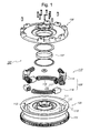
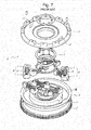
- FIG. 1 is an exploded perspective view showing a dual mass flywheel according to the present invention.
- FIG. 2 shows perspective views showing a top of a primary flywheel and a bottom of a secondary flywheel of the dual mass according to the present invention.
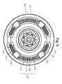
- FIG. 3 is a plan view showing a state in which a spring and spring guides are mounted to the dual mass flywheel according to present invention.
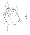
- FIG. 4 is a perspective view showing a spring guide applied to the dual mass flywheel according to the related art.
- FIG. 5 is a schematic diagram showing a mounted state of the spring guide applied to the dual mass flywheel according to the present invention.
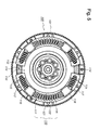
- FIG. 6 is a plan view showing an operation state of the dual mass flywheel according to the present invention.
- the dual mass flywheel 100 includes a primary flywheel 105 having a ring gear 101 and connected to an output shaft of an engine, a secondary flywheel 106 connected to an input shaft of a transmission, a coupling unit 107 for coupling the primary flywheel 105 and the secondary flywheel 106, the coupling unit 107 having an ancillary configuration such as a sleeve, a bushing, a rivet, and a flange, a drive unit 110 coupled to an upper surface (with reference to FIG.
- a unit groove 111 for accommodating the drive unit 110 is formed in the primary flywheel 105, and two pairs of separation prevention bosses 113 each of which has an operation slot 112 therebetween are formed above and below a center line of the unit groove 111 to prevent the left and right drive units 110 from deviating from proper positions thereof.
- a pair of driving pins 114 for pressing and dampening the drive unit 110 during a rotation of the drive unit 110 integrally protrudes from a bottom surface of the secondary flywheel 106 such that they are located in the operation slots 112 formed between the separation prevention bosses 114 formed in the primary flywheel 105 to press the drive unit 110.
- the present invention improves a torsion spring 108 and spring guides 109 constituting the drive unit 110 so that the torsion spring 108 can be stably held, and minimizes frictional resistance with the unit groove 111 in the operation process to secure operability.
- a linear spring 117 is interposed between an end guide 115 and a middle guide 116 and a curved spring 118 is interposed between the middle guides 116 to prevent a contacting point thereof from being pushed to the outside by a centrifugal force, thereby absorbing various noises and vibrations.
- One linear spring 117 and one curved spring 118 may be provided, but a dual structure in which a small diameter linear spring and a small diameter curved spring are installed within a large diameter linear spring 117 and a large diameter curved spring 118 may be provided.
- a guide body 120 whose upper and lower surfaces are flat is formed by integrally forming spring maintainers 119 at opposite sides of the spring guide 109 including the end guides 115 and the middle guides 116 so that the torsion spring 108 can be maintained.
- An inner circumferential surface 123 and an outer circumferential surface 124 of the guide body 120 contacting an inner wall surface 121 and an outer wall surface 122 of the unit groove 111 formed in the primary flywheel 105 are inclined toward the guide body 120 by a predetermined angle ⁇ to be spaced apart from the inner wall surface 121 and the outer wall surface 122 of the unit groove 111 at a contacting point P of the guide body 120 so that the guide body 120 can always maintain point contacts with the inner and outer wall surfaces 121 and 122 of the unit groove 111 even if centrifugal force is generated when the dual mass flywheel 100 is operated, minimizing frictional resistance.
- an inner circumferential surface 123 and an outer circumferential surface 124 of the guide body 120 of the middle guide 116 contacting an inner wall surface 121 and an outer wall surface 122 of the unit groove 111 formed in the primary flywheel 105 are inclined to make a predetermined angle ⁇ between the tangents of central portions of the inner circumferential surface 123 and the outer circumferential surface 124, and an inner circumferential surface 121 and an outer circumferential surface 122 of the guide body 120 of the middle guide 116 respectively, to be spaced apart from the inner wall surface 121 and the outer wall surface 122 of the unit groove 111 so that the guide body 120 maintains a contacting point P contacts with the inner and outer wall surfaces 121,122 of the unit groove 111.
- the angle ⁇ formed on the inner surface 123 and the outer surface 124 of the guide body 120 is not limited, but when the angle ⁇ is too gentle, they may contact the inner wall surface 121 and the outer wall surface 122 of the unit groove 111, whereas when the angle ⁇ is too large, the point contact may be excellent but it becomes difficult to form the spring maintainer 119 for maintaining the spring 108.
- Spring grooves 125 and the spring maintainers 119 are formed at opposite sides of the guide body 120 of the middle guide 116 to accommodate opposite ends of the linear spring 117 and the curved spring 118, and a maintaining boss 126 protrudes at a center of the spring groove 125 to be coupled to and maintained at inner diameter parts of the linear spring 117 and the curved spring 118.
- the present invention is adapted to transmit rotation power of the primary flywheel 105 connected to an output shaft of the engine to the second flywheel 106 to transmit the rotation power to the transmission, normally transmit a torque necessary for travel of the vehicle in the process, and reduce noise, an impact, and vibrations generated in the power transmitting process. It is well known in the art that the function of the present invention is performed by the drive unit 100 interposed between the primary flywheel 105 and the secondary flywheel 106, and a detailed description thereof will be omitted and effects and advantages of the present invention will be described below.
- the main feature of the dual mass flywheel 100 according to the present invention is that the middle guide 116 constituting the spring guide 109 inserted into the unit groove 111 formed in the primary flywheel 105 maintains point contacts with the inner wall surface 121 and the outer wall surface 122 of the unit groove 111 to be operated, minimizing frictional resistance and securing operability during an operation process.
- the inner circumferential surface 123 and the outer circumferential surface 124 of the middle guide 116 of the guide body 120 do not have the same circumferences as those of the inner wall surface 121 and the outer wall surface 122 of the unit groove 111 except the contacting point P, but have curves of a predetermined angle ⁇ , only the contacting point P of the guide body 120 can maintain to contacts with the inner wall surface 121 and the outer wall surface 122 of the unit groove 111.
- the torsion spring 108 is dually configured by the linear spring 117 interposed between the end guide 115 and the middle guide 116 and the curved spring 118 interposed between the middle guides 116, the contacting point thereof is prevented from being pushed to the outside by a centrifugal force generated when the dual mass flywheel 100 is operated, and thus various noise and vibrations can be absorbed.
- torsion spring 108 is dually configured by the linear spring 117 and the curved spring 118, it can be designed easily, considering centrifugal force, centripetal force, noise, and vibrations, while securing variability in many different ways.
- the spring maintainers 119 formed at opposite sides of the end guide 115 and the middle guide 116 is constituted by the maintaining bosses 126 for maintaining the spring groove 125 for accommodating the outer diameter part of the torsion spring 108 and the inner diameter part of the torsion spring 108, stably holding the torsion spring 108 and securing operability.
- the present invention improves the spring guides and the springs constituting the drive unit for point contact to minimize frictional resistance, thereby securing operability, and absorbs noise and vibrations of various characteristics to increase quality and durability.
Landscapes
- Engineering & Computer Science (AREA)
- General Engineering & Computer Science (AREA)
- Physics & Mathematics (AREA)
- Acoustics & Sound (AREA)
- Aviation & Aerospace Engineering (AREA)
- Mechanical Engineering (AREA)
- Mechanical Operated Clutches (AREA)
- Connection Of Motors, Electrical Generators, Mechanical Devices, And The Like (AREA)
- Gears, Cams (AREA)
Applications Claiming Priority (1)
| Application Number | Priority Date | Filing Date | Title |
|---|---|---|---|
| KR1020120154851A KR101400592B1 (ko) | 2012-12-27 | 2012-12-27 | 듀얼 매스 플라이휠 |
Publications (2)
| Publication Number | Publication Date |
|---|---|
| EP2749788A2 true EP2749788A2 (de) | 2014-07-02 |
| EP2749788A3 EP2749788A3 (de) | 2014-07-09 |
Family
ID=49666975
Family Applications (1)
| Application Number | Title | Priority Date | Filing Date |
|---|---|---|---|
| EP13193582.7A Withdrawn EP2749788A3 (de) | 2012-12-27 | 2013-11-19 | Zweimassenschwungrad |
Country Status (5)
| Country | Link |
|---|---|
| US (1) | US20140182412A1 (de) |
| EP (1) | EP2749788A3 (de) |
| KR (1) | KR101400592B1 (de) |
| CN (1) | CN103899707A (de) |
| BR (1) | BR102013019960A2 (de) |
Cited By (1)
| Publication number | Priority date | Publication date | Assignee | Title |
|---|---|---|---|---|
| US10422408B2 (en) | 2015-03-19 | 2019-09-24 | Exedy Corporation | Dynamic vibration absorbing device and fluid coupling |
Families Citing this family (10)
| Publication number | Priority date | Publication date | Assignee | Title |
|---|---|---|---|---|
| KR101386865B1 (ko) * | 2012-11-26 | 2014-04-17 | 평화크랏치공업 주식회사 | 듀얼 매스 플라이휠 |
| KR101693985B1 (ko) * | 2015-05-11 | 2017-01-09 | 현대자동차주식회사 | 차량용 댐핑 장치 |
| WO2017029931A1 (ja) | 2015-08-20 | 2017-02-23 | 株式会社エクセディ | トルク変動抑制装置、トルクコンバータ、及び動力伝達装置 |
| EP3362703B1 (de) * | 2015-10-12 | 2020-04-01 | Schaeffler Technologies AG & Co. KG | Drehschwingungsdämpfer |
| CN106195117A (zh) * | 2016-08-25 | 2016-12-07 | 易随科技股份有限公司 | 惯性飞轮传动组件及具有惯性飞轮传动组件的系统 |
| CN106763486A (zh) * | 2017-01-04 | 2017-05-31 | 四川大学 | 新型多间隙磁流变液双质量飞轮 |
| CN108730409B (zh) * | 2017-04-20 | 2020-05-01 | 上海汽车集团股份有限公司 | 汽车和双质量飞轮 |
| CN110966348B (zh) * | 2020-01-12 | 2023-01-31 | 华东交通大学 | 一种采用双层减振弹簧的汽车双质量飞轮 |
| CN111564929B (zh) * | 2020-05-26 | 2021-02-19 | 胡妍 | 主备用电机切换装置 |
| CN112112929A (zh) * | 2020-09-22 | 2020-12-22 | 华域动力总成部件系统(上海)有限公司 | 直弹簧与弧形弹簧混合的扭转减振器 |
Citations (1)
| Publication number | Priority date | Publication date | Assignee | Title |
|---|---|---|---|---|
| KR20120134598A (ko) | 2011-06-03 | 2012-12-12 | 주식회사 케이티 | 컨텐츠 이어보기 제공 시스템 및 방법 |
Family Cites Families (17)
| Publication number | Priority date | Publication date | Assignee | Title |
|---|---|---|---|---|
| US4620621A (en) * | 1984-04-02 | 1986-11-04 | Borg-Warner Corporation | Centrifugally activated roller clutch/overrunning clutch |
| JPH02109024U (de) * | 1989-02-17 | 1990-08-30 | ||
| SE464990B (sv) * | 1989-09-20 | 1991-07-08 | Volvo Ab | Svaenghjul foer foerbraenningsmotorer |
| DE4128868A1 (de) * | 1991-08-30 | 1993-03-04 | Fichtel & Sachs Ag | Zweimassenschwungrad mit gleitschuh |
| DE69735182T2 (de) * | 1996-08-30 | 2006-08-03 | Aisin Seiki K.K., Kariya | Kraftübertragungsmechanismus |
| DE19749678C1 (de) * | 1997-11-10 | 1998-12-10 | Mannesmann Sachs Ag | Drehschwingungsdämpfer |
| US6854580B2 (en) * | 2003-02-06 | 2005-02-15 | Borgwarner, Inc. | Torsional damper having variable bypass clutch with centrifugal release mechanism |
| US7343832B2 (en) | 2003-02-14 | 2008-03-18 | Luk Lamellen Und Kupplungsbau Beteiligungs Kg | Torsional vibration damper |
| KR100610853B1 (ko) * | 2004-08-11 | 2006-08-09 | 현대자동차주식회사 | 비틀림 진동 댐퍼 |
| KR20070087609A (ko) * | 2004-12-22 | 2007-08-28 | 루크 라멜렌 운트 쿠플룽스바우베타일리궁스 카게 | 비틀림 진동 댐퍼 |
| JP4925893B2 (ja) * | 2007-03-30 | 2012-05-09 | 日産自動車株式会社 | スプリングシートおよびダンパーディスク組立体 |
| DE102007016744A1 (de) * | 2007-04-07 | 2008-10-09 | Zf Friedrichshafen Ag | Torsionsschwingungsdämpfer |
| DE102007033164A1 (de) * | 2007-07-17 | 2009-01-22 | Zf Friedrichshafen Ag | Torsionsschwingungsdämpferanordnung |
| DE112009005528B4 (de) * | 2008-07-24 | 2020-08-13 | Exedy Corp. | Dämpfungsmechanismus und Schwungradanordnung |
| KR101058573B1 (ko) * | 2008-09-10 | 2011-08-23 | 주식회사평화발레오 | 댐퍼플라이휠 |
| KR101011111B1 (ko) * | 2008-09-19 | 2011-01-25 | 주식회사평화발레오 | 댐퍼플라이휠 |
| KR101241009B1 (ko) * | 2011-05-17 | 2013-03-11 | 현대자동차주식회사 | 듀얼 매스 플라이휠 |
-
2012
- 2012-12-27 KR KR1020120154851A patent/KR101400592B1/ko not_active Expired - Fee Related
-
2013
- 2013-06-17 CN CN201310238337.1A patent/CN103899707A/zh active Pending
- 2013-07-16 US US13/943,531 patent/US20140182412A1/en not_active Abandoned
- 2013-08-06 BR BR102013019960A patent/BR102013019960A2/pt not_active Application Discontinuation
- 2013-11-19 EP EP13193582.7A patent/EP2749788A3/de not_active Withdrawn
Patent Citations (1)
| Publication number | Priority date | Publication date | Assignee | Title |
|---|---|---|---|---|
| KR20120134598A (ko) | 2011-06-03 | 2012-12-12 | 주식회사 케이티 | 컨텐츠 이어보기 제공 시스템 및 방법 |
Cited By (1)
| Publication number | Priority date | Publication date | Assignee | Title |
|---|---|---|---|---|
| US10422408B2 (en) | 2015-03-19 | 2019-09-24 | Exedy Corporation | Dynamic vibration absorbing device and fluid coupling |
Also Published As
| Publication number | Publication date |
|---|---|
| CN103899707A (zh) | 2014-07-02 |
| BR102013019960A2 (pt) | 2016-03-29 |
| US20140182412A1 (en) | 2014-07-03 |
| EP2749788A3 (de) | 2014-07-09 |
| KR101400592B1 (ko) | 2014-05-27 |
Similar Documents
| Publication | Publication Date | Title |
|---|---|---|
| EP2749788A2 (de) | Zweimassenschwungrad | |
| CN105324589B (zh) | 转矩传递装置 | |
| US8840481B2 (en) | Power transmission part, damper mechanism, and flywheel assembly | |
| JP5891557B2 (ja) | トルクリミッタ付きダンパ | |
| EP2735762A2 (de) | Zweimassenschwungrad | |
| US8568243B2 (en) | Flywheel assembly | |
| JP6756129B2 (ja) | ダンパ装置 | |
| US11204078B2 (en) | Vibration damping device | |
| US8978861B2 (en) | Friction clutch plate with damping springs | |
| EP3578853A1 (de) | Vibrationsdämpfungsvorrichtung | |
| CN105980735A (zh) | 减震装置以及起动装置 | |
| JP5817918B2 (ja) | 捩り振動減衰装置 | |
| CN103765039A (zh) | 扭矩传递装置 | |
| KR100494886B1 (ko) | 진동감쇠장치 | |
| KR101129671B1 (ko) | 이중댐퍼구조를 가지는 차량용 토크 컨버터 | |
| JPWO2018199323A1 (ja) | 振動減衰装置 | |
| KR100452260B1 (ko) | 진동감쇠장치 | |
| JP2011052726A (ja) | ロックアップダンパ装置 | |
| JPWO2018199324A1 (ja) | 振動減衰装置 | |
| JP5742756B2 (ja) | 捩り振動減衰装置 | |
| KR101200677B1 (ko) | 댐퍼 플라이휠 | |
| JP2005282651A (ja) | 捩り振動低減装置 | |
| KR101099123B1 (ko) | 듀얼 메스 플라이휠 | |
| KR20110106186A (ko) | 듀얼 메스 플라이휠 | |
| KR101050103B1 (ko) | 듀얼 메스 플라이휠 |
Legal Events
| Date | Code | Title | Description |
|---|---|---|---|
| PUAL | Search report despatched |
Free format text: ORIGINAL CODE: 0009013 |
|
| 17P | Request for examination filed |
Effective date: 20131119 |
|
| AK | Designated contracting states |
Kind code of ref document: A2 Designated state(s): AL AT BE BG CH CY CZ DE DK EE ES FI FR GB GR HR HU IE IS IT LI LT LU LV MC MK MT NL NO PL PT RO RS SE SI SK SM TR |
|
| AX | Request for extension of the european patent |
Extension state: BA ME |
|
| PUAI | Public reference made under article 153(3) epc to a published international application that has entered the european phase |
Free format text: ORIGINAL CODE: 0009012 |
|
| AK | Designated contracting states |
Kind code of ref document: A3 Designated state(s): AL AT BE BG CH CY CZ DE DK EE ES FI FR GB GR HR HU IE IS IT LI LT LU LV MC MK MT NL NO PL PT RO RS SE SI SK SM TR |
|
| AX | Request for extension of the european patent |
Extension state: BA ME |
|
| RIC1 | Information provided on ipc code assigned before grant |
Ipc: F16F 15/134 20060101AFI20140603BHEP |
|
| STAA | Information on the status of an ep patent application or granted ep patent |
Free format text: STATUS: THE APPLICATION IS DEEMED TO BE WITHDRAWN |
|
| 18D | Application deemed to be withdrawn |
Effective date: 20150110 |