EP2749794A1 - Fabrication de gobelets d'emballage - Google Patents
Fabrication de gobelets d'emballage Download PDFInfo
- Publication number
- EP2749794A1 EP2749794A1 EP20120461569 EP12461569A EP2749794A1 EP 2749794 A1 EP2749794 A1 EP 2749794A1 EP 20120461569 EP20120461569 EP 20120461569 EP 12461569 A EP12461569 A EP 12461569A EP 2749794 A1 EP2749794 A1 EP 2749794A1
- Authority
- EP
- European Patent Office
- Prior art keywords
- lubrication
- oil duct
- front face
- inner disc
- residual
- Prior art date
- Legal status (The legal status is an assumption and is not a legal conclusion. Google has not performed a legal analysis and makes no representation as to the accuracy of the status listed.)
- Granted
Links
Images





Classifications
-
- F—MECHANICAL ENGINEERING; LIGHTING; HEATING; WEAPONS; BLASTING
- F16—ENGINEERING ELEMENTS AND UNITS; GENERAL MEASURES FOR PRODUCING AND MAINTAINING EFFECTIVE FUNCTIONING OF MACHINES OR INSTALLATIONS; THERMAL INSULATION IN GENERAL
- F16J—PISTONS; CYLINDERS; SEALINGS
- F16J15/00—Sealings
- F16J15/16—Sealings between relatively-moving surfaces
- F16J15/26—Sealings between relatively-moving surfaces with stuffing-boxes for rigid sealing rings
-
- F—MECHANICAL ENGINEERING; LIGHTING; HEATING; WEAPONS; BLASTING
- F16—ENGINEERING ELEMENTS AND UNITS; GENERAL MEASURES FOR PRODUCING AND MAINTAINING EFFECTIVE FUNCTIONING OF MACHINES OR INSTALLATIONS; THERMAL INSULATION IN GENERAL
- F16J—PISTONS; CYLINDERS; SEALINGS
- F16J15/00—Sealings
- F16J15/16—Sealings between relatively-moving surfaces
- F16J15/162—Special parts or details relating to lubrication or cooling of the sealing itself
-
- B—PERFORMING OPERATIONS; TRANSPORTING
- B23—MACHINE TOOLS; METAL-WORKING NOT OTHERWISE PROVIDED FOR
- B23P—METAL-WORKING NOT OTHERWISE PROVIDED FOR; COMBINED OPERATIONS; UNIVERSAL MACHINE TOOLS
- B23P11/00—Connecting or disconnecting metal parts or objects by metal-working techniques not otherwise provided for
- B23P11/02—Connecting or disconnecting metal parts or objects by metal-working techniques not otherwise provided for by first expanding and then shrinking or vice versa, e.g. by using pressure fluids; by making force fits
- B23P11/022—Connecting or disconnecting metal parts or objects by metal-working techniques not otherwise provided for by first expanding and then shrinking or vice versa, e.g. by using pressure fluids; by making force fits by using pressure fluids
-
- B—PERFORMING OPERATIONS; TRANSPORTING
- B23—MACHINE TOOLS; METAL-WORKING NOT OTHERWISE PROVIDED FOR
- B23P—METAL-WORKING NOT OTHERWISE PROVIDED FOR; COMBINED OPERATIONS; UNIVERSAL MACHINE TOOLS
- B23P11/00—Connecting or disconnecting metal parts or objects by metal-working techniques not otherwise provided for
- B23P11/02—Connecting or disconnecting metal parts or objects by metal-working techniques not otherwise provided for by first expanding and then shrinking or vice versa, e.g. by using pressure fluids; by making force fits
- B23P11/025—Connecting or disconnecting metal parts or objects by metal-working techniques not otherwise provided for by first expanding and then shrinking or vice versa, e.g. by using pressure fluids; by making force fits by using heat or cold
-
- F—MECHANICAL ENGINEERING; LIGHTING; HEATING; WEAPONS; BLASTING
- F16—ENGINEERING ELEMENTS AND UNITS; GENERAL MEASURES FOR PRODUCING AND MAINTAINING EFFECTIVE FUNCTIONING OF MACHINES OR INSTALLATIONS; THERMAL INSULATION IN GENERAL
- F16J—PISTONS; CYLINDERS; SEALINGS
- F16J15/00—Sealings
- F16J15/16—Sealings between relatively-moving surfaces
- F16J15/26—Sealings between relatively-moving surfaces with stuffing-boxes for rigid sealing rings
- F16J15/28—Sealings between relatively-moving surfaces with stuffing-boxes for rigid sealing rings with sealing rings made of metal
-
- Y—GENERAL TAGGING OF NEW TECHNOLOGICAL DEVELOPMENTS; GENERAL TAGGING OF CROSS-SECTIONAL TECHNOLOGIES SPANNING OVER SEVERAL SECTIONS OF THE IPC; TECHNICAL SUBJECTS COVERED BY FORMER USPC CROSS-REFERENCE ART COLLECTIONS [XRACs] AND DIGESTS
- Y10—TECHNICAL SUBJECTS COVERED BY FORMER USPC
- Y10T—TECHNICAL SUBJECTS COVERED BY FORMER US CLASSIFICATION
- Y10T29/00—Metal working
- Y10T29/49—Method of mechanical manufacture
- Y10T29/49826—Assembling or joining
- Y10T29/49863—Assembling or joining with prestressing of part
- Y10T29/49867—Assembling or joining with prestressing of part of skin on frame member
-
- Y—GENERAL TAGGING OF NEW TECHNOLOGICAL DEVELOPMENTS; GENERAL TAGGING OF CROSS-SECTIONAL TECHNOLOGIES SPANNING OVER SEVERAL SECTIONS OF THE IPC; TECHNICAL SUBJECTS COVERED BY FORMER USPC CROSS-REFERENCE ART COLLECTIONS [XRACs] AND DIGESTS
- Y10—TECHNICAL SUBJECTS COVERED BY FORMER USPC
- Y10T—TECHNICAL SUBJECTS COVERED BY FORMER US CLASSIFICATION
- Y10T29/00—Metal working
- Y10T29/49—Method of mechanical manufacture
- Y10T29/49826—Assembling or joining
- Y10T29/49863—Assembling or joining with prestressing of part
- Y10T29/49876—Assembling or joining with prestressing of part by snap fit
Definitions
- the subject matter disclosed herein relates to manufacturing of mechanical components subject to high pressure stresses.
- the present disclosure relates to manufacturing of packing cups for reciprocating compressors, especially hyper-compressors.
- Hyper compressors those capable of producing gas pressure levels up to or above 3,000 bars, are widely used in industrial application, including, but not limited to, the production of low density polyethylene, or LDPE.
- Hyper-compressors must withstand very high delivery pressures and pressure fluctuations between discharge and suction and can be considered one of the most stressed pressure vessels in the industry. Due to very high pulsating pressures and consequent fatigue stresses, hyper-compressors require pre-stressing of cylinder components, to prevent crack propagation. Packing cups are among the most critical components of a hyper-compressor.
- Pre-stressing is obtained by shrink-fitting and autofrettage.
- Shrink-fitting is a technique whereby an outer cylinder or an outer disc and an inner cylinder, or an inner disc, are assembled together with a high degree of mutual interference.
- the inner disc is cooled down to a very low temperature, for example around -190°C and the outer disc is heated up to a high temperature, e.g. 370°C.
- the inner disc is then fitted into a hole of the outer disc.
- Usual packing cups are manufactured by shrink-fitting an inner disc and an outer disc together.
- Autofrettage consists in plastically yielding an internal surface or an inner layer of a component, by means of a hydraulic pressure of several hundreds MPa.
- the yielded portion is highly compressed by the elastic recovery of the non-yielded surrounding material. This is due to the fact that the inner portion of the material has been subjected to a deformation beyond the limit of elastic yielding and therefore cannot return to its original shape and dimension. Consequently, the elastic stress applied by the surrounding material maintains the inner plastically yielded material under compressive conditions.
- Autofrettage involves complex technical problems, such as the selection of suitable seals to withstand the high pressure values required, the selection of proper pressure-transmitting oil and the accuracy of pressure measurements.
- Pre-stressing of components subject to high pressure and pressure fluctuations is an essential measure to prevent crack propagations.
- the value of the compressive pre-stress induced in the component shall be such as to prevent tensile stresses to be induced in the material during operation by the fluid contained in the component, e.g. lubrication oil. Possible cracks present in the inner surface of a component are thus maintained in a "closed" condition. Compressive stresses inside a flaw or crack do not contribute to the crack growth. However, if the pressure of the fluid inside the component is greater than the actual compressive stress (in module), pressure propagates in the flaw and can contribute to crack propagation. If the pressure fluctuates and the peak value is higher than the compressive stress, fatigue is induced in the component, which can eventually lead to crack propagation and failure of the component.
- Hyper-compressor packing cups are usually manufactured by shrink-fitting an outer disc and an inner disc together and subsequently subjecting the lubrication oil ducts present in the inner disc to autofrettage to generate a compressive pre-stress in the material surrounding the lubrication oil ducts. More details on manufacturing of packing cups for hyper-compressors are disclosed e.g. in E.Giacomelli et al.,"Autofrettaging procedures on LDPE Hyper-Compressor Components", Proceedings of 2006 ASME Pressure Vessels and Piping Division Conference, July 23-27, 2006, Vancouver, Canada .
- Embodiments of the method disclosed herein provides for an additional machining step in the manufacturing of packing cups, in particular packing cups for hyper-compressors.
- the additional machining step is aimed at removing a most external layer on both faces of the inner disc of the packing cup after autofrettage. This results in removing the volume of the material surrounding the lubrication-oil duct(s) of the inner disc where the residual hoop stresses and/or the residual equivalent stresses induced by autofrettage are insufficient to prevent potential expansion of accidental cracks, which might be present on the inner surface of the lubrication-oil duct(s).
- a method of manufacturing a packing cup for a hyper-compressor comprising the following steps:
- the method preferably includes a step of shrink-fitting the inner disc and an outer disc after autofrettaging the lubrication-oil duct and removing the thickness on both the first front face and the second front face of the inner disc.
- the present subject matter disclosed herein also relates to a packing cup for hyper-compressors and to a hyper-compressor comprising one or more packing cups, manufactured according to the above-disclosed method.
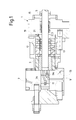
- Fig. 1 illustrates a sectional view
- Fig.2 illustrates a perspective cut-out view of a portion of a hyper-compressor 1.
- the hyper-compressor comprises a cylinder or packing spacer 3, wherein a plunger or piston rod 5 is arranged.
- the plunger slides reciprocatingly in the cylinder 3.
- Reference numbers 7 and 9 indicate the suction port and the discharge port, respectively, of compressor 1. Movement of the plunger 5 in the cylinder 3 sucks fluid through the suction port 7 and discharges fluid at a higher pressure through the discharge port 9.
- a poppet valve 7A is arranged in the suction port 7 and a poppet valve 9A is arranged in the discharge port 9.
- the poppet valves 7A, 9A are arranged in a valve body 11 housed in a cylinder head 13. The cylinder 3 is locked between the cylinder head 13 and a flange 15.
- Each packing cup 17 comprises a central hole 18.
- the central hole 18 is surrounded by a seat 17A for a gasket (not shown) slidingly sealing against the cylindrical surface of the plunger 5, which reciprocatingly moves through the packing cups 17.
- Lubrication oil is delivered to the packing cups 17 through lubrication quills 19.
- One or more lubrication lines 21 are provided, which are formed across the packing cups 17.
- Each packing cup 17 comprises one or more lubrication-oil ducts 23 extending through the packing cup 17, from a first face to a second face thereof.
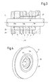
- the lubrication-oil ducts 23 and the packing cups 17 are arranged so that one or more continuous lubrication lines 21 are formed across the entire stack of packing cups 17, as shown in Fig. 3 , by aligned lubrication-oil ducts 23 of the packing cups 17.
- lubrication-oil ducts 23 are provided in packing cup 17. It shall be understood, however, that a different number of lubrication-oil ducts can be provided. In general, the number of lubrication-oil ducts can differ from one packing cup to the other, to lubricate different sealing rings.
- each packing cup 17 comprises two shrink-fitted discs. More specifically, an inner disc 25 is shrink-fitted in an outer disc 27. The central hole 18 and the lubrication-oil ducts 23 are formed in the inner disc 25.
- the packing cup 17 is manufactured according to a step sequence as summarized in Figs. 5, 6A-6C .
- the inner disc 25 with a central hole 18 and lubrication-oil ducts 23 is provided; see Fig. 5 , step 101 and Fig.6A .
- Reference numbers 25X, 25Y designate respectively a first front planar face and a second front planar face of the inner disc 25.
- the lubrication-oil ducts 23 are subject to autofrettage ( Fig.5 , step 102) by introducing therein oil at high pressure.
- the pressurized oil in the lubrication-oil ducts 23 cause the innermost layer of material surrounding each lubrication-oil duct to plastically yield, while the outermost material is subject to elastic deformation. Once the autofrettage oil pressure is released, the outer elastically-deformed material recovers while the inner plastically yielded material does not recover its original shape. This generates a compressive pre-stress in the material of the inner disc 25 surrounding the lubrication-oil ducts 23.
- the inner disc 25 is machined ( Fig.5 , step 103) to remove an outer thickness of the material from the two planar faces 25X, 25Y of the inner disc 25.
- a thinner disc having a thickness S2 is thus obtained ( Fig.6B ).
- a layer having a thickness D is removed from both sides of the inner disc 25.
- the thickness D of each removed layer is between 0 and 50%, e.g. advantageously between 1% and 30%, for example between 5 and 20% or 5 and 30% of the total axial dimension S1 of the inner disc 25. In some embodiments, between 7% and 15% of the total thickness S1 is removed from each face or side of the inner disc 25.
- the inner disc 25 and an outer disc 27 are shrink-fitted according to standard procedure; see Fig.5 , step 104, and Fig. 6C . After shrink-fitting the gasket seat 17A can be machined.
- autofrettage is obtained by applying a high pressure, in the range of e.g. 13,000 Bar, in the lubrication-oil ducts 23 provided in the inner disc 25 of a packing cup 17, by means of an autofrettage equipment.
- the pressure inside the lubrication-oil duct 23 causes a plastic deformation of the innermost layers of the material surrounding the lubrication-oil duct.
- a disc of indefinite axial length i.e.
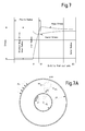
- Fig.7A provides a pictorial definition of the radial stress ( ⁇ r ) and hoop stress ( ⁇ ⁇ ) respectively.
- the radial stress is the stress in the radial direction and the hoop stress is the stress in the tangential direction.
- Tensile stresses are conventionally indicated as positive (+) values, compressive stresses are conventionally indicated as negative (-) values.
- the stress distribution illustrated in Fig.7 has been obtained by treating the plastically deformed inner layer of the disc material surrounding the lubrication-oil duct applying an elasto-plastic model according to ASME code to evaluate the stress/strain distribution in the yielded material and the correction for Bauschinger effect has been introduced in order to correctly evaluate the maximum residual compressive stress (hence the plastic region dimension) induced by autofrettage.
- Fig.7 the distance from the axis of the lubrication-oil duct is reported on the horizontal axis and the stress is reported on the vertical axis.
- R1 indicates the inner radius of the lubrication-oil duct and R2 indicates the so-called plastic radius, i.e. the radius of the plastically deformed material surrounding the lubrication-oil duct.
- the two curves reported on the diagram of Fig. 7 represent the radial stress and the hoop stress respectively. Due to local plastic deformation in the inner layer surrounding the lubrication-oil duct, a residual hoop stress is obtained at the inner radius R1, i.e. at the surface of the lubrication-oil duct.
- the vital characteristics for fatigue life improvement are the residual hoop stresses at inner radius and the plastic radius dimension, hence the depth of the plastically deformed layer.
- Fig.8 illustrates the residual hoop stress ( Fig.8A ) and the residual radial stress ( Fig.8B ) in the end region of the lubrication-oil duct 23.
- Fig.8C illustrates the so-called "von Mises stress” (also known as "equivalent stress”) in the terminal portion of the lubrication-oil duct.
- the residual stress distribution is represented by constant-stress curves, each curve representing the location where the respective (hoop or radial) stress has a constant value, the value being reported on each curve and is expressed in MPa.
- both the residual radial stresses as well as the residual hoop stresses become positive (tensile stress) in the boundary area at the end of the lubrication-oil duct.
- the residual hoop stress is not reversed (i.e. remains negative).
- the residual hoop stress has a much lower modulus than in the central area of the lubrication-oil duct and is, therefore, insufficient for the purposes of preventing fatigue-promoted crack propagation. Absent any subsequent machining step, during operation the tensile stresses induced in the material by the pressure fluctuations inside the lubrication-oil duct become greater than the residual compressive pre-stress. Any flaw present in the material would then be expanded and pressurized oil would penetrate therein. The cyclic fluctuation of the lubrication-oil pressure would lead to crack formation and propagation and eventually to failure of the packing cup.
- Figs. 9A, 9B and 9C are similar to Figs. 8A-8C , and illustrate the same terminal area of the lubrication-oil duct, after removing the outermost layer of the inner disc 25. Curves of equal residual stresses are represented, with the value of the residual stress expressed in MPa being reported on each curve. As can be appreciated from these figures, the residual compressive hoop and radial stresses, as well as the von Mises stresses in the portion of material forming the disc after machining are substantially higher than those in the removed layers.
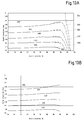
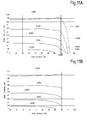
- Figs.10A and 10B illustrate the residual von Mises stresses, i.e. the residual equivalent stresses in the area surrounding one end of a lubrication-oil duct after autofrettage and before removal of the outer layer of material forming the inner disc ( Fig.10A ) as well as after removal of the outer layer ( Fig.10B ).
- the values reported on the individual curves indicate the equivalent residual stress measured in MPa.
- On the horizontal axis the axial coordinate along the lubrication-oil duct is reported, starting from the central point of the duct. The axial coordinate is normalized with respect to the total length of the duct (% length).
- the radial coordinate i.e. the distance from the axis of the lubrication-oil duct, is reported on the vertical axis.
- Figs. 11A and 11B illustrate the residual equivalent plastic strain after autofrettage, respectively before ( Fig.11A ) and after ( Fig.11B ) removal of the outer material layer from the inner disc 25.
- the vertical and horizontal axes report the radial and axial coordinates, respectively. The values on each curve are expressed in fractional strain (mm/mm).
- Figs 12A and 12B illustrate, in a manner similar to Figs. 10A and 10B , the residual hoop stresses after autofrettage of the lubrication-oil duct. More specifically, Fig.12A illustrates the residual hoop stresses before machining of the disc for removing the outer layers. Fig.12B illustrates the residual hoop stresses after machining.
- the curves in both figures are curves of constant stress values, i.e. curves along which the residual hoop stress remains constant. The stress value is reported on each curve and is expressed in MPa.
- the horizontal axis represents the axial coordinate (in %, expressed in mm/mm, starting from the center of the lubrication-oil duct), i.e. the distance, in axial direction, from the duct center.
- the vertical axis represents the radial coordinate (in mm), i.e. the distance from the axis of the lubrication-oil duct in the radial direction.
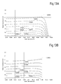
- Figs. 13A and 13B show the residual hoop strains after autofrettage, respectively before ( Fig.13A ) and after ( Fig.13B ) machining and removal of the outer layers of the disc.
- the vertical and horizontal axes show the same parameters as in Figs. 12A, 12B .
- the residual stress is expressed in MPa
- the residual strain is reported.
- machining removes the most critical boundary area at each end of the lubrication-oil duct, where an insufficient residual stress is present.
- the remaining part of the lubrication-oil duct is therefore capable of better resisting fatigue stress and is less prone to crack formation and propagation.
- each curve represents a value of the residual equivalent stress, i.e. von Mises stress.
- Each curve is substantially parallel to the abscissa, i.e. to the axis of the lubrication-oil duct.
- the residual equivalent stress varies less than 25% along the a direction parallel to the axis of the lubrication-oil duct.
- the residual equivalent von Mises stress after autofrettage fluctuates around 500 MPa.
- the innermost volume surrounding the lubrication-oil duct shows an even more constant value of the residual stress, with fluctuations equal to or less than 15% or even equal to or less than 10%.
- the variation of the residual equivalent stresses along the axial coordinate is substantially smaller than in prior art packing cups.
- moving along the axial coordinate the residual equivalent (von Mises) stress varies less than 15% and preferably less than 10% in the first 10% of the axial length, starting from the disc surface.
- the residual hoop stresses along the inner surface of the lubrication-oil duct after autofrettage and removal of the outer material layer will remain always negative, i.e. the residual hoop stresses will always be compressive stresses. Additionally, the residual hoop stress along the entire surface of the lubrication-oil duct will always be at least 20% of the maximum residual loop stress, at the center of the lubrication-oil duct. Subsequent shrink fitting of the two discs 25, 27 does not significantly affect this situation.
- Residual stresses and strains in the material surrounding the lubrication-oil duct can be measured by neutron scattering technique. Therefore, the method performed for manufacturing a packing cup can be determined from residual strains and stresses measured on the machined packing cup even after shrink-fitting.
Landscapes
- Engineering & Computer Science (AREA)
- General Engineering & Computer Science (AREA)
- Mechanical Engineering (AREA)
- Gasket Seals (AREA)
- Sealing Devices (AREA)
- Compressor (AREA)
- Sealing With Elastic Sealing Lips (AREA)
Priority Applications (10)
| Application Number | Priority Date | Filing Date | Title |
|---|---|---|---|
| ES12461569.1T ES2553231T3 (es) | 2012-12-27 | 2012-12-27 | Fabricación de copas de empaquetadura |
| HUE12461569A HUE026149T2 (en) | 2012-12-27 | 2012-12-27 | Production of gland |
| EP12461569.1A EP2749794B1 (fr) | 2012-12-27 | 2012-12-27 | Fabrication de gobelets d'emballage |
| JP2015550057A JP6348510B2 (ja) | 2012-12-27 | 2013-12-20 | パッキンカップの製造 |
| BR112015015580A BR112015015580B8 (pt) | 2012-12-27 | 2013-12-20 | Método para fabricar um anel de vedação para um hipercompressor, anel de vedação para hipercompressores e hipercompressor |
| US14/758,067 US10697545B2 (en) | 2012-12-27 | 2013-12-20 | Packing cups manufacturing |
| RU2015125175A RU2636601C2 (ru) | 2012-12-27 | 2013-12-20 | Изготовление уплотнительных манжет |
| KR1020157020188A KR102121481B1 (ko) | 2012-12-27 | 2013-12-20 | 하이퍼 압축기용 패킹 컵, 이를 포함하는 하이퍼 압축기 및 하이퍼 압축기용 패킹 컵의 제조 방법 |
| PCT/EP2013/077827 WO2014102217A1 (fr) | 2012-12-27 | 2013-12-20 | Fabrication de coupelles d'étanchéité |
| CN201380073943.0A CN105308369B (zh) | 2012-12-27 | 2013-12-20 | 填料盘制造 |
Applications Claiming Priority (1)
| Application Number | Priority Date | Filing Date | Title |
|---|---|---|---|
| EP12461569.1A EP2749794B1 (fr) | 2012-12-27 | 2012-12-27 | Fabrication de gobelets d'emballage |
Publications (2)
| Publication Number | Publication Date |
|---|---|
| EP2749794A1 true EP2749794A1 (fr) | 2014-07-02 |
| EP2749794B1 EP2749794B1 (fr) | 2015-09-30 |
Family
ID=47632774
Family Applications (1)
| Application Number | Title | Priority Date | Filing Date |
|---|---|---|---|
| EP12461569.1A Active EP2749794B1 (fr) | 2012-12-27 | 2012-12-27 | Fabrication de gobelets d'emballage |
Country Status (10)
| Country | Link |
|---|---|
| US (1) | US10697545B2 (fr) |
| EP (1) | EP2749794B1 (fr) |
| JP (1) | JP6348510B2 (fr) |
| KR (1) | KR102121481B1 (fr) |
| CN (1) | CN105308369B (fr) |
| BR (1) | BR112015015580B8 (fr) |
| ES (1) | ES2553231T3 (fr) |
| HU (1) | HUE026149T2 (fr) |
| RU (1) | RU2636601C2 (fr) |
| WO (1) | WO2014102217A1 (fr) |
Cited By (1)
| Publication number | Priority date | Publication date | Assignee | Title |
|---|---|---|---|---|
| WO2016087326A1 (fr) * | 2014-12-05 | 2016-06-09 | Nuovo Pignone Srl | Boîte à garniture pour machine à piston alternatif et son procédé d'assemblage |
Families Citing this family (2)
| Publication number | Priority date | Publication date | Assignee | Title |
|---|---|---|---|---|
| US10883483B2 (en) | 2018-09-28 | 2021-01-05 | Air Products And Chemicals, Inc. | Seal assembly for reciprocating compressor |
| US20260049607A1 (en) * | 2024-08-15 | 2026-02-19 | Marathon Petroleum Company Lp | Assemblies and methods for enhancing diversion of gas and/or fluid from operation of a reciprocating compressor |
Citations (4)
| Publication number | Priority date | Publication date | Assignee | Title |
|---|---|---|---|---|
| FR2346576A1 (fr) * | 1976-03-29 | 1977-10-28 | Dart Ind Inc | Lubrification du cylindre d'un compresseur a piston |
| US5873575A (en) * | 1997-04-21 | 1999-02-23 | Delaware Capital Formation, Inc. | Fluid cooled packing case member for compressors and other machinery |
| EP1146263A2 (fr) * | 2000-04-10 | 2001-10-17 | Hoerbiger Kompressortechnik Services GmbH | Garniture d'étanchéité |
| EP2302090A1 (fr) * | 2009-09-28 | 2011-03-30 | Nuovo Pignone S.p.A. | Stuffing box pour compresseur réciproques. Fabriqué au moins en partie en acier à haute resistance de composition C: 0.13-0.17%; Cr:1.8-2.20%; Ni: 9.5-10.5%; Co:13.5-14.5%; Mo:0.90-1.10; Al<0.015%; Ti<0.015%;Mn<0.10%; Si<0.10%; S<0.005%; P<0.008%. |
Family Cites Families (13)
| Publication number | Priority date | Publication date | Assignee | Title |
|---|---|---|---|---|
| GB457025A (en) * | 1934-10-26 | 1936-11-19 | Gustav Huhn | Stuffing box packing |
| GB928749A (en) * | 1960-07-28 | 1963-06-12 | Union Carbide Corp | Improvements in or relating to seals |
| US4163561A (en) * | 1978-08-15 | 1979-08-07 | Dart Industries Inc. | Fatigue resistant fittings and methods of fabrication |
| US4809993A (en) * | 1987-06-17 | 1989-03-07 | Henshaw Terrance L | Stuffing box sealing device |
| JPH04126058U (ja) * | 1991-05-08 | 1992-11-17 | 三菱重工業株式会社 | 圧力容器 |
| CN2512952Y (zh) * | 2001-12-12 | 2002-09-25 | 张福焕 | 用于密封机构的连续填料装置 |
| JP4721863B2 (ja) | 2005-10-14 | 2011-07-13 | 株式会社山武 | 弁装置 |
| ITMI20080770A1 (it) | 2008-04-24 | 2009-10-25 | Nuovo Pignone Spa | Scatola premistoppa per compressori alternativi |
| CN201318443Y (zh) * | 2008-08-08 | 2009-09-30 | 张进 | 组合密封装置 |
| AT507431B1 (de) * | 2009-01-29 | 2010-05-15 | Hoerbiger Kompressortechnik | Segmentierter packungsring |
| JP2011075071A (ja) * | 2009-10-01 | 2011-04-14 | Nuovo Pignone Holding Spa | 往復圧縮機用のパッキン箱ケーシング |
| CN102042198A (zh) * | 2009-10-16 | 2011-05-04 | 诺沃皮尼奥内有限公司 | 往复式压缩机的填料箱壳体 |
| RU108534U1 (ru) * | 2011-04-21 | 2011-09-20 | Борис Семенович Захаров | Механическое уплотнение деталей с наружной цилиндрической поверхностью |
-
2012
- 2012-12-27 EP EP12461569.1A patent/EP2749794B1/fr active Active
- 2012-12-27 HU HUE12461569A patent/HUE026149T2/en unknown
- 2012-12-27 ES ES12461569.1T patent/ES2553231T3/es active Active
-
2013
- 2013-12-20 WO PCT/EP2013/077827 patent/WO2014102217A1/fr not_active Ceased
- 2013-12-20 BR BR112015015580A patent/BR112015015580B8/pt active IP Right Grant
- 2013-12-20 JP JP2015550057A patent/JP6348510B2/ja active Active
- 2013-12-20 RU RU2015125175A patent/RU2636601C2/ru active
- 2013-12-20 US US14/758,067 patent/US10697545B2/en active Active
- 2013-12-20 CN CN201380073943.0A patent/CN105308369B/zh active Active
- 2013-12-20 KR KR1020157020188A patent/KR102121481B1/ko active Active
Patent Citations (4)
| Publication number | Priority date | Publication date | Assignee | Title |
|---|---|---|---|---|
| FR2346576A1 (fr) * | 1976-03-29 | 1977-10-28 | Dart Ind Inc | Lubrification du cylindre d'un compresseur a piston |
| US5873575A (en) * | 1997-04-21 | 1999-02-23 | Delaware Capital Formation, Inc. | Fluid cooled packing case member for compressors and other machinery |
| EP1146263A2 (fr) * | 2000-04-10 | 2001-10-17 | Hoerbiger Kompressortechnik Services GmbH | Garniture d'étanchéité |
| EP2302090A1 (fr) * | 2009-09-28 | 2011-03-30 | Nuovo Pignone S.p.A. | Stuffing box pour compresseur réciproques. Fabriqué au moins en partie en acier à haute resistance de composition C: 0.13-0.17%; Cr:1.8-2.20%; Ni: 9.5-10.5%; Co:13.5-14.5%; Mo:0.90-1.10; Al<0.015%; Ti<0.015%;Mn<0.10%; Si<0.10%; S<0.005%; P<0.008%. |
Non-Patent Citations (1)
| Title |
|---|
| E.GIACOMELLI ET AL.: "Autofrettaging procedures on LDPE Hyper-Compressor Components", PROCEEDINGS OF 2006 ASME PRESSURE VESSELS AND PIPING DIVISION CONFERENCE, pages 20060623 |
Cited By (2)
| Publication number | Priority date | Publication date | Assignee | Title |
|---|---|---|---|---|
| WO2016087326A1 (fr) * | 2014-12-05 | 2016-06-09 | Nuovo Pignone Srl | Boîte à garniture pour machine à piston alternatif et son procédé d'assemblage |
| US10563766B2 (en) | 2014-12-05 | 2020-02-18 | Nuovo Pigone Srl | Packing case for reciprocating machine and method of assembling the same |
Also Published As
| Publication number | Publication date |
|---|---|
| BR112015015580B1 (pt) | 2021-04-06 |
| KR102121481B1 (ko) | 2020-06-11 |
| JP2016503152A (ja) | 2016-02-01 |
| WO2014102217A1 (fr) | 2014-07-03 |
| US20150330511A1 (en) | 2015-11-19 |
| CN105308369B (zh) | 2017-07-11 |
| US10697545B2 (en) | 2020-06-30 |
| HUE026149T2 (en) | 2016-05-30 |
| JP6348510B2 (ja) | 2018-06-27 |
| CN105308369A (zh) | 2016-02-03 |
| BR112015015580B8 (pt) | 2023-02-14 |
| EP2749794B1 (fr) | 2015-09-30 |
| RU2636601C2 (ru) | 2017-11-24 |
| KR20150100885A (ko) | 2015-09-02 |
| RU2015125175A (ru) | 2017-01-30 |
| BR112015015580A2 (pt) | 2017-07-11 |
| ES2553231T3 (es) | 2015-12-07 |
Similar Documents
| Publication | Publication Date | Title |
|---|---|---|
| CN112166270B (zh) | 带密封件的阀和阀座 | |
| AU2018206739B2 (en) | Pipe end fitting with improved venting | |
| US11112063B2 (en) | Sensor for a high-pressure line, and method for producing same | |
| US10697545B2 (en) | Packing cups manufacturing | |
| US10514031B2 (en) | Packaging bore for eliminating washout failure | |
| CN106457327B (zh) | 用于加压流体的容器的制造方法及其设备 | |
| EP3663616B1 (fr) | Joint métallique | |
| JP2009180090A (ja) | 低温流体用昇圧ポンプのピストンリング | |
| KR20160057286A (ko) | 개스킷 및 개스킷의 제조방법 | |
| US20040021270A1 (en) | Two piece oil control ring with nitrided surface layers | |
| EP3098496B1 (fr) | Raccord à vis pour tuyau | |
| US20030146229A1 (en) | Pressure vessels for high pressure applications | |
| CN201152245Y (zh) | 往复式压缩机填料组件的自紧式减压环 | |
| CN105909182A (zh) | 一种高压管汇强度失效的判定方法 | |
| Parker | Compound and monobloc cylinders incorporating reverse-autofrettage to reduce external hoop stresses | |
| Giacomelli et al. | Autofrettaging procedures on LDPE hyper-compressor components | |
| EP3113942A1 (fr) | Récipient cylindrique multicouche à haute pression particulièrement adapté pour un traitement à haute pression | |
| Lei et al. | Design of packing cup interference fit value of hypercompressors for low density polyethylene production | |
| Maggi et al. | New manufacturing cycle to improve the life of packing cups for hyper-compressors | |
| Fazzini et al. | Cause and effect assessment after a complex failure of a large ethylene compressor | |
| EP3726102B1 (fr) | Ensemble de scellement annulaire | |
| Maggi et al. | All-Purpose Packing Cups for Hyper Compressor | |
| Kamal et al. | Fatigue Life Enhancement of Thermally Autofrettaged Cylinders through Shrink-Fit | |
| Volterrani et al. | Design of Oil Injection Quills for Hypercompressors Cylinders | |
| US20200399847A1 (en) | Pneumatic fender |
Legal Events
| Date | Code | Title | Description |
|---|---|---|---|
| 17P | Request for examination filed |
Effective date: 20121227 |
|
| AK | Designated contracting states |
Kind code of ref document: A1 Designated state(s): AL AT BE BG CH CY CZ DE DK EE ES FI FR GB GR HR HU IE IS IT LI LT LU LV MC MK MT NL NO PL PT RO RS SE SI SK SM TR |
|
| AX | Request for extension of the european patent |
Extension state: BA ME |
|
| PUAI | Public reference made under article 153(3) epc to a published international application that has entered the european phase |
Free format text: ORIGINAL CODE: 0009012 |
|
| R17P | Request for examination filed (corrected) |
Effective date: 20150105 |
|
| RAX | Requested extension states of the european patent have changed |
Extension state: ME Payment date: 20150105 Extension state: BA Payment date: 20150105 |
|
| RBV | Designated contracting states (corrected) |
Designated state(s): AL AT BE BG CH CY CZ DE DK EE ES FI FR GB GR HR HU IE IS IT LI LT LU LV MC MK MT NL NO PL PT RO RS SE SI SK SM TR |
|
| GRAP | Despatch of communication of intention to grant a patent |
Free format text: ORIGINAL CODE: EPIDOSNIGR1 |
|
| INTG | Intention to grant announced |
Effective date: 20150527 |
|
| GRAS | Grant fee paid |
Free format text: ORIGINAL CODE: EPIDOSNIGR3 |
|
| GRAA | (expected) grant |
Free format text: ORIGINAL CODE: 0009210 |
|
| AK | Designated contracting states |
Kind code of ref document: B1 Designated state(s): AL AT BE BG CH CY CZ DE DK EE ES FI FR GB GR HR HU IE IS IT LI LT LU LV MC MK MT NL NO PL PT RO RS SE SI SK SM TR |
|
| AX | Request for extension of the european patent |
Extension state: BA ME |
|
| REG | Reference to a national code |
Ref country code: CH Ref legal event code: EP Ref country code: GB Ref legal event code: FG4D |
|
| REG | Reference to a national code |
Ref country code: AT Ref legal event code: REF Ref document number: 752610 Country of ref document: AT Kind code of ref document: T Effective date: 20151015 |
|
| REG | Reference to a national code |
Ref country code: IE Ref legal event code: FG4D |
|
| REG | Reference to a national code |
Ref country code: DE Ref legal event code: R096 Ref document number: 602012011089 Country of ref document: DE |
|
| REG | Reference to a national code |
Ref country code: RO Ref legal event code: EPE |
|
| REG | Reference to a national code |
Ref country code: ES Ref legal event code: FG2A Ref document number: 2553231 Country of ref document: ES Kind code of ref document: T3 Effective date: 20151207 |
|
| REG | Reference to a national code |
Ref country code: SE Ref legal event code: TRGR |
|
| REG | Reference to a national code |
Ref country code: FR Ref legal event code: PLFP Year of fee payment: 4 |
|
| PG25 | Lapsed in a contracting state [announced via postgrant information from national office to epo] |
Ref country code: LV Free format text: LAPSE BECAUSE OF FAILURE TO SUBMIT A TRANSLATION OF THE DESCRIPTION OR TO PAY THE FEE WITHIN THE PRESCRIBED TIME-LIMIT Effective date: 20150930 Ref country code: LT Free format text: LAPSE BECAUSE OF FAILURE TO SUBMIT A TRANSLATION OF THE DESCRIPTION OR TO PAY THE FEE WITHIN THE PRESCRIBED TIME-LIMIT Effective date: 20150930 Ref country code: NO Free format text: LAPSE BECAUSE OF FAILURE TO SUBMIT A TRANSLATION OF THE DESCRIPTION OR TO PAY THE FEE WITHIN THE PRESCRIBED TIME-LIMIT Effective date: 20151230 Ref country code: GR Free format text: LAPSE BECAUSE OF FAILURE TO SUBMIT A TRANSLATION OF THE DESCRIPTION OR TO PAY THE FEE WITHIN THE PRESCRIBED TIME-LIMIT Effective date: 20151231 |
|
| REG | Reference to a national code |
Ref country code: NL Ref legal event code: FP |
|
| REG | Reference to a national code |
Ref country code: LT Ref legal event code: MG4D |
|
| PG25 | Lapsed in a contracting state [announced via postgrant information from national office to epo] |
Ref country code: RS Free format text: LAPSE BECAUSE OF FAILURE TO SUBMIT A TRANSLATION OF THE DESCRIPTION OR TO PAY THE FEE WITHIN THE PRESCRIBED TIME-LIMIT Effective date: 20150930 Ref country code: HR Free format text: LAPSE BECAUSE OF FAILURE TO SUBMIT A TRANSLATION OF THE DESCRIPTION OR TO PAY THE FEE WITHIN THE PRESCRIBED TIME-LIMIT Effective date: 20150930 |
|
| PG25 | Lapsed in a contracting state [announced via postgrant information from national office to epo] |
Ref country code: EE Free format text: LAPSE BECAUSE OF FAILURE TO SUBMIT A TRANSLATION OF THE DESCRIPTION OR TO PAY THE FEE WITHIN THE PRESCRIBED TIME-LIMIT Effective date: 20150930 Ref country code: IS Free format text: LAPSE BECAUSE OF FAILURE TO SUBMIT A TRANSLATION OF THE DESCRIPTION OR TO PAY THE FEE WITHIN THE PRESCRIBED TIME-LIMIT Effective date: 20160130 |
|
| REG | Reference to a national code |
Ref country code: SK Ref legal event code: T3 Ref document number: E 19891 Country of ref document: SK |
|
| REG | Reference to a national code |
Ref country code: HU Ref legal event code: AG4A Ref document number: E026149 Country of ref document: HU |
|
| PG25 | Lapsed in a contracting state [announced via postgrant information from national office to epo] |
Ref country code: PT Free format text: LAPSE BECAUSE OF FAILURE TO SUBMIT A TRANSLATION OF THE DESCRIPTION OR TO PAY THE FEE WITHIN THE PRESCRIBED TIME-LIMIT Effective date: 20160201 Ref country code: PL Free format text: LAPSE BECAUSE OF FAILURE TO SUBMIT A TRANSLATION OF THE DESCRIPTION OR TO PAY THE FEE WITHIN THE PRESCRIBED TIME-LIMIT Effective date: 20150930 |
|
| REG | Reference to a national code |
Ref country code: DE Ref legal event code: R097 Ref document number: 602012011089 Country of ref document: DE |
|
| PG25 | Lapsed in a contracting state [announced via postgrant information from national office to epo] |
Ref country code: MC Free format text: LAPSE BECAUSE OF FAILURE TO SUBMIT A TRANSLATION OF THE DESCRIPTION OR TO PAY THE FEE WITHIN THE PRESCRIBED TIME-LIMIT Effective date: 20150930 Ref country code: LU Free format text: LAPSE BECAUSE OF FAILURE TO SUBMIT A TRANSLATION OF THE DESCRIPTION OR TO PAY THE FEE WITHIN THE PRESCRIBED TIME-LIMIT Effective date: 20151227 |
|
| PLBE | No opposition filed within time limit |
Free format text: ORIGINAL CODE: 0009261 |
|
| STAA | Information on the status of an ep patent application or granted ep patent |
Free format text: STATUS: NO OPPOSITION FILED WITHIN TIME LIMIT |
|
| PG25 | Lapsed in a contracting state [announced via postgrant information from national office to epo] |
Ref country code: DK Free format text: LAPSE BECAUSE OF FAILURE TO SUBMIT A TRANSLATION OF THE DESCRIPTION OR TO PAY THE FEE WITHIN THE PRESCRIBED TIME-LIMIT Effective date: 20150930 |
|
| 26N | No opposition filed |
Effective date: 20160701 |
|
| REG | Reference to a national code |
Ref country code: IE Ref legal event code: MM4A |
|
| PG25 | Lapsed in a contracting state [announced via postgrant information from national office to epo] |
Ref country code: IE Free format text: LAPSE BECAUSE OF NON-PAYMENT OF DUE FEES Effective date: 20151227 |
|
| PG25 | Lapsed in a contracting state [announced via postgrant information from national office to epo] |
Ref country code: SI Free format text: LAPSE BECAUSE OF FAILURE TO SUBMIT A TRANSLATION OF THE DESCRIPTION OR TO PAY THE FEE WITHIN THE PRESCRIBED TIME-LIMIT Effective date: 20150930 |
|
| REG | Reference to a national code |
Ref country code: FR Ref legal event code: PLFP Year of fee payment: 5 |
|
| PG25 | Lapsed in a contracting state [announced via postgrant information from national office to epo] |
Ref country code: SM Free format text: LAPSE BECAUSE OF FAILURE TO SUBMIT A TRANSLATION OF THE DESCRIPTION OR TO PAY THE FEE WITHIN THE PRESCRIBED TIME-LIMIT Effective date: 20150930 Ref country code: BG Free format text: LAPSE BECAUSE OF FAILURE TO SUBMIT A TRANSLATION OF THE DESCRIPTION OR TO PAY THE FEE WITHIN THE PRESCRIBED TIME-LIMIT Effective date: 20150930 |
|
| PG25 | Lapsed in a contracting state [announced via postgrant information from national office to epo] |
Ref country code: CY Free format text: LAPSE BECAUSE OF FAILURE TO SUBMIT A TRANSLATION OF THE DESCRIPTION OR TO PAY THE FEE WITHIN THE PRESCRIBED TIME-LIMIT Effective date: 20150930 |
|
| PG25 | Lapsed in a contracting state [announced via postgrant information from national office to epo] |
Ref country code: MT Free format text: LAPSE BECAUSE OF FAILURE TO SUBMIT A TRANSLATION OF THE DESCRIPTION OR TO PAY THE FEE WITHIN THE PRESCRIBED TIME-LIMIT Effective date: 20150930 |
|
| REG | Reference to a national code |
Ref country code: FR Ref legal event code: PLFP Year of fee payment: 6 |
|
| REG | Reference to a national code |
Ref country code: AT Ref legal event code: UEP Ref document number: 752610 Country of ref document: AT Kind code of ref document: T Effective date: 20150930 |
|
| PG25 | Lapsed in a contracting state [announced via postgrant information from national office to epo] |
Ref country code: MK Free format text: LAPSE BECAUSE OF FAILURE TO SUBMIT A TRANSLATION OF THE DESCRIPTION OR TO PAY THE FEE WITHIN THE PRESCRIBED TIME-LIMIT Effective date: 20150930 |
|
| PG25 | Lapsed in a contracting state [announced via postgrant information from national office to epo] |
Ref country code: AL Free format text: LAPSE BECAUSE OF FAILURE TO SUBMIT A TRANSLATION OF THE DESCRIPTION OR TO PAY THE FEE WITHIN THE PRESCRIBED TIME-LIMIT Effective date: 20150930 |
|
| REG | Reference to a national code |
Ref country code: BE Ref legal event code: PD Owner name: NUOVO PIGNONE TECNOLOGIE - S.R.L.; IT Free format text: DETAILS ASSIGNMENT: CHANGE OF OWNER(S), ASSIGNMENT; FORMER OWNER NAME: NUOVO PIGNONE S.R.L. Effective date: 20220210 |
|
| REG | Reference to a national code |
Ref country code: HU Ref legal event code: GB9C Owner name: NUOVO PIGNONE TECNOLOGIE - S.R.L., IT Free format text: FORMER OWNER(S): NUOVO PIGNONE S.R.L., IT Ref country code: HU Ref legal event code: FH1C Free format text: FORMER REPRESENTATIVE(S): MESZAROSNE DONUSZ KATALIN, SBGK SZABADALMI UEGYVIVOEI IRODA, HU Representative=s name: SBGK SZABADALMI UEGYVIVOEI IRODA, HU |
|
| REG | Reference to a national code |
Ref country code: CH Ref legal event code: PK Free format text: BERICHTIGUNGEN |
|
| REG | Reference to a national code |
Ref country code: FI Ref legal event code: PCE Owner name: NUOVO PIGNONE TECNOLOGIE - S.R.L. |
|
| REG | Reference to a national code |
Ref country code: ES Ref legal event code: PC2A Owner name: NUOVO PIGNONE TECNOLOGIE - S.R.L. Effective date: 20220628 |
|
| REG | Reference to a national code |
Ref country code: NL Ref legal event code: PD Owner name: NUOVO PIGNONE TECNOLOGIE - S.R.L.; IT Free format text: DETAILS ASSIGNMENT: CHANGE OF OWNER(S), ASSIGNMENT; FORMER OWNER NAME: NUOVO PIGNONE S.R.L. Effective date: 20220621 |
|
| REG | Reference to a national code |
Ref country code: GB Ref legal event code: 732E Free format text: REGISTERED BETWEEN 20220728 AND 20220803 |
|
| REG | Reference to a national code |
Ref country code: AT Ref legal event code: PC Ref document number: 752610 Country of ref document: AT Kind code of ref document: T Owner name: NUOVO PIGNONE TECNOLOGIE - S.R.L., IT Effective date: 20230124 |
|
| REG | Reference to a national code |
Ref country code: DE Ref legal event code: R081 Ref document number: 602012011089 Country of ref document: DE Owner name: NUOVO PIGNONE TECNOLOGIE - S.R.L., IT Free format text: FORMER OWNER: NUOVO PIGNONE S.R.L., 50127 FLORENCE, IT |
|
| PGFP | Annual fee paid to national office [announced via postgrant information from national office to epo] |
Ref country code: NL Payment date: 20251119 Year of fee payment: 14 |
|
| REG | Reference to a national code |
Ref country code: CH Ref legal event code: U11 Free format text: ST27 STATUS EVENT CODE: U-0-0-U10-U11 (AS PROVIDED BY THE NATIONAL OFFICE) Effective date: 20260101 |
|
| PGFP | Annual fee paid to national office [announced via postgrant information from national office to epo] |
Ref country code: DE Payment date: 20251126 Year of fee payment: 14 |
|
| PGFP | Annual fee paid to national office [announced via postgrant information from national office to epo] |
Ref country code: GB Payment date: 20251119 Year of fee payment: 14 |
|
| PGFP | Annual fee paid to national office [announced via postgrant information from national office to epo] |
Ref country code: AT Payment date: 20251121 Year of fee payment: 14 |
|
| PGFP | Annual fee paid to national office [announced via postgrant information from national office to epo] |
Ref country code: IT Payment date: 20251119 Year of fee payment: 14 Ref country code: FI Payment date: 20251119 Year of fee payment: 14 |
|
| PGFP | Annual fee paid to national office [announced via postgrant information from national office to epo] |
Ref country code: HU Payment date: 20251212 Year of fee payment: 14 Ref country code: FR Payment date: 20251120 Year of fee payment: 14 |
|
| PGFP | Annual fee paid to national office [announced via postgrant information from national office to epo] |
Ref country code: TR Payment date: 20251127 Year of fee payment: 14 Ref country code: BE Payment date: 20251119 Year of fee payment: 14 |
|
| PGFP | Annual fee paid to national office [announced via postgrant information from national office to epo] |
Ref country code: SE Payment date: 20251119 Year of fee payment: 14 |
|
| PGFP | Annual fee paid to national office [announced via postgrant information from national office to epo] |
Ref country code: CZ Payment date: 20251212 Year of fee payment: 14 |
|
| PGFP | Annual fee paid to national office [announced via postgrant information from national office to epo] |
Ref country code: RO Payment date: 20251219 Year of fee payment: 14 Ref country code: SK Payment date: 20251125 Year of fee payment: 14 |
|
| PGFP | Annual fee paid to national office [announced via postgrant information from national office to epo] |
Ref country code: ES Payment date: 20260102 Year of fee payment: 14 |
|
| PGFP | Annual fee paid to national office [announced via postgrant information from national office to epo] |
Ref country code: CH Payment date: 20260101 Year of fee payment: 14 |
|
| REG | Reference to a national code |
Ref country code: FI Ref legal event code: PCE Owner name: NUOVO PIGNONE S.R.L |
|
| REG | Reference to a national code |
Ref country code: SK Ref legal event code: PC4A Ref document number: E 19891 Country of ref document: SK Owner name: NUOVO PIGNONE S.R.L., FIRENZE (FI), IT Free format text: FORMER OWNER: NUOVO PIGNONE TECNOLOGIE - S.R.L., FIRENZE, IT Effective date: 20260708 |
|
| REG | Reference to a national code |
Ref country code: NL Ref legal event code: PD Owner name: NUOVO PIGNONE S.R.L.; IT Free format text: DETAILS ASSIGNMENT: CHANGE OF OWNER(S), MERGE; FORMER OWNER NAME: NUOVO PIGNONE TECNOLOGIE - S.R.L. Effective date: 20260722 |