EP2749801A1 - Clip de fixation - Google Patents
Clip de fixation Download PDFInfo
- Publication number
- EP2749801A1 EP2749801A1 EP13197669.8A EP13197669A EP2749801A1 EP 2749801 A1 EP2749801 A1 EP 2749801A1 EP 13197669 A EP13197669 A EP 13197669A EP 2749801 A1 EP2749801 A1 EP 2749801A1
- Authority
- EP
- European Patent Office
- Prior art keywords
- frame
- receiving space
- line
- pivoting
- web
- Prior art date
- Legal status (The legal status is an assumption and is not a legal conclusion. Google has not performed a legal analysis and makes no representation as to the accuracy of the status listed.)
- Withdrawn
Links
- 230000037431 insertion Effects 0.000 claims abstract description 23
- 238000003780 insertion Methods 0.000 claims abstract description 23
- 230000002093 peripheral effect Effects 0.000 abstract 1
- 230000006978 adaptation Effects 0.000 description 1
- 230000000903 blocking effect Effects 0.000 description 1
- 230000001010 compromised effect Effects 0.000 description 1
- 238000010276 construction Methods 0.000 description 1
- 230000000694 effects Effects 0.000 description 1
- 238000000605 extraction Methods 0.000 description 1
- 238000009434 installation Methods 0.000 description 1
- 230000007306 turnover Effects 0.000 description 1
Images


Classifications
-
- H—ELECTRICITY
- H02—GENERATION; CONVERSION OR DISTRIBUTION OF ELECTRIC POWER
- H02G—INSTALLATION OF ELECTRIC CABLES OR LINES, OR OF COMBINED OPTICAL AND ELECTRIC CABLES OR LINES
- H02G3/00—Installations of electric cables or lines or protective tubing therefor in or on buildings, equivalent structures or vehicles
- H02G3/36—Installations of cables or lines in walls, floors or ceilings
-
- F—MECHANICAL ENGINEERING; LIGHTING; HEATING; WEAPONS; BLASTING
- F16—ENGINEERING ELEMENTS AND UNITS; GENERAL MEASURES FOR PRODUCING AND MAINTAINING EFFECTIVE FUNCTIONING OF MACHINES OR INSTALLATIONS; THERMAL INSULATION IN GENERAL
- F16L—PIPES; JOINTS OR FITTINGS FOR PIPES; SUPPORTS FOR PIPES, CABLES OR PROTECTIVE TUBING; MEANS FOR THERMAL INSULATION IN GENERAL
- F16L3/00—Supports for pipes, cables or protective tubing, e.g. hangers, holders, clamps, cleats, clips, brackets
- F16L3/08—Supports for pipes, cables or protective tubing, e.g. hangers, holders, clamps, cleats, clips, brackets substantially surrounding the pipe, cable or protective tubing
- F16L3/12—Supports for pipes, cables or protective tubing, e.g. hangers, holders, clamps, cleats, clips, brackets substantially surrounding the pipe, cable or protective tubing comprising a member substantially surrounding the pipe, cable or protective tubing
- F16L3/1203—Supports for pipes, cables or protective tubing, e.g. hangers, holders, clamps, cleats, clips, brackets substantially surrounding the pipe, cable or protective tubing comprising a member substantially surrounding the pipe, cable or protective tubing with a pair of arms moved automatically to closed position by overcenter spring
-
- F—MECHANICAL ENGINEERING; LIGHTING; HEATING; WEAPONS; BLASTING
- F16—ENGINEERING ELEMENTS AND UNITS; GENERAL MEASURES FOR PRODUCING AND MAINTAINING EFFECTIVE FUNCTIONING OF MACHINES OR INSTALLATIONS; THERMAL INSULATION IN GENERAL
- F16B—DEVICES FOR FASTENING OR SECURING CONSTRUCTIONAL ELEMENTS OR MACHINE PARTS TOGETHER, e.g. NAILS, BOLTS, CIRCLIPS, CLAMPS, CLIPS OR WEDGES; JOINTS OR JOINTING
- F16B2/00—Friction-grip releasable fastenings
- F16B2/20—Clips, i.e. with gripping action effected solely by the inherent resistance to deformation of the material of the fastening
-
- F—MECHANICAL ENGINEERING; LIGHTING; HEATING; WEAPONS; BLASTING
- F16—ENGINEERING ELEMENTS AND UNITS; GENERAL MEASURES FOR PRODUCING AND MAINTAINING EFFECTIVE FUNCTIONING OF MACHINES OR INSTALLATIONS; THERMAL INSULATION IN GENERAL
- F16L—PIPES; JOINTS OR FITTINGS FOR PIPES; SUPPORTS FOR PIPES, CABLES OR PROTECTIVE TUBING; MEANS FOR THERMAL INSULATION IN GENERAL
- F16L3/00—Supports for pipes, cables or protective tubing, e.g. hangers, holders, clamps, cleats, clips, brackets
- F16L3/08—Supports for pipes, cables or protective tubing, e.g. hangers, holders, clamps, cleats, clips, brackets substantially surrounding the pipe, cable or protective tubing
- F16L3/12—Supports for pipes, cables or protective tubing, e.g. hangers, holders, clamps, cleats, clips, brackets substantially surrounding the pipe, cable or protective tubing comprising a member substantially surrounding the pipe, cable or protective tubing
- F16L3/13—Supports for pipes, cables or protective tubing, e.g. hangers, holders, clamps, cleats, clips, brackets substantially surrounding the pipe, cable or protective tubing comprising a member substantially surrounding the pipe, cable or protective tubing and engaging it by snap action
-
- H—ELECTRICITY
- H02—GENERATION; CONVERSION OR DISTRIBUTION OF ELECTRIC POWER
- H02G—INSTALLATION OF ELECTRIC CABLES OR LINES, OR OF COMBINED OPTICAL AND ELECTRIC CABLES OR LINES
- H02G3/00—Installations of electric cables or lines or protective tubing therefor in or on buildings, equivalent structures or vehicles
- H02G3/30—Installations of cables or lines on walls, floors or ceilings
- H02G3/32—Installations of cables or lines on walls, floors or ceilings using mounting clamps
-
- Y—GENERAL TAGGING OF NEW TECHNOLOGICAL DEVELOPMENTS; GENERAL TAGGING OF CROSS-SECTIONAL TECHNOLOGIES SPANNING OVER SEVERAL SECTIONS OF THE IPC; TECHNICAL SUBJECTS COVERED BY FORMER USPC CROSS-REFERENCE ART COLLECTIONS [XRACs] AND DIGESTS
- Y10—TECHNICAL SUBJECTS COVERED BY FORMER USPC
- Y10T—TECHNICAL SUBJECTS COVERED BY FORMER US CLASSIFICATION
- Y10T24/00—Buckles, buttons, clasps, etc.
- Y10T24/39—Cord and rope holders
- Y10T24/3936—Pivoted part
- Y10T24/3953—Pivotal means with plate aperture
Definitions
- the invention relates to a fastening clip for at least one line, with a frame defining a receiving space for the line, in which the line can be introduced so that the frame surrounds the line in the circumferential direction, wherein the frame is provided an insertion opening for the line , And with at least one mounted on the frame arm, which can be moved from a holding position in which the conduit is fixed in the receiving space in a pivoting direction in a mounting position in which the conduit can be introduced through the insertion opening in the receiving space.
- Fixing clips of this type are used to attach a cable, such as a cable, in a simple manner.
- the line can be easily inserted through the insertion opening into the frame of the pre-mounted, for example, on a fixture mounting clips and lock in this behind the pivot arms, so that a simple, tool-free attachment of the line is possible.
- the object of the invention is to provide a mounting clip that allows easy installation of the line, but provides improved fixation of the line.
- a mounting clip for at least one line is provided with a frame defining a receiving space for the line, in which the line can be introduced so that the frame surrounds the line in the circumferential direction, wherein the frame has an insertion opening for the Line is provided, and with at least one mounted on the frame arm, which can be moved from a holding position in which the conduit is fixed in the receiving space in a pivoting direction in a mounting position in which the conduit can be introduced through the insertion opening in the receiving space wherein a ridge is provided, which is attached to a first end of the pivot arm and with a second end on the inside of the frame, wherein the web has at least one joint and is folded in the mounting position.
- the web is attached to the swivel arm and the frame so that a movement from the holding position against the pivoting direction is not possible. In such a movement, the web is stretched or loaded on train and thus keeps the swing arm reliably in the holding position.
- the provided in the web joint has the advantage that the bridge when pivoting the swivel arm can be easily folded into the mounting position, so that the web during pivoting of the swivel arm in the mounting position provides no resistance and also can be folded to save space.
- a projection can be provided on the swivel arm and / or on the frame which abuts against a bearing surface on the frame and / or on the swivel arm during pivoting of the swivel arm out of the holding position against the pivoting direction passes and blocks a pivoting of the pivot arm against the pivoting direction.
- This projection in combination with the contact surface has the same effect as a web according to the invention, namely that pivoting of the swivel arm against the pivoting direction out of the receiving space is prevented.
- the projection may, for example, be arranged outside the receiving space or on the outside of the frame. This offers the advantage that no additional components are present within the frame, whereby the receiving space can be used completely for the line.
- the swivel arm is preferably mounted on an edge of the insertion opening, so that it can close the insertion opening in the holding position or at least reduce the width of the insertion opening so far that withdrawal of the line from the receiving space is not possible.
- pivot arms are provided, which are provided on opposite edges of the insertion opening and which are pivoted in opposite directions in the mounting position.
- the insertion opening can be made larger, since it can be closed by both pivot arms, whereby larger lines can be inserted into the mounting clip and the mounting clip is more flexible.
- the web is preferably stretched in the holding position and is loaded in a further pivoting of the pivot arm from the receiving space to train, so that no movement of the pivot arm from the holding position against the pivoting direction is possible.
- the web is bent at least in sections in the holding position, so that a small movement of the pivot arm out of the holding position is possible, but in any case pivoting of the pivot arm is prevented from the receiving space out.
- the web can abut with a bent portion on the line, so that the line is additionally supported by the web.
- biasing of the web can be done by the inserted line, so that it is loaded to train and pivoting of the pivot arm is prevented from the receiving space out.
- Abstützlasche may be provided which act on the line with a spring force, so that the line is resiliently mounted in the frame.
- these Abstützlaschen can serve as a tolerance compensation for different sized lines.
- FIGS. 1a and 1b a fastening clip 10 'is shown in the prior art.
- the mounting clip has a frame 12 ', which is formed in the embodiment shown here is substantially square and a receiving space 14' limited.
- the frame 12 ' has an interruption in the circumferential direction U, which forms an insertion opening 16', through which a line 18 'in the receiving space 14' can be inserted.
- a pivot arm 22 ' is provided, which can be moved from the holding position shown here in a pivoting direction S' in the receiving space 14 'in a mounting position in which the line 18' in an insertion direction e 'can be inserted into the receiving space 14'. If the line 18 'completely inserted, the pivot arms 22' against the pivoting direction S 'spring back into the holding position, so that the line 18' in the receiving space 14 'is fixed.
- attachment clips 10 substantially corresponds to the structure of the in the FIGS. 1a and 1b shown fastening clips, so that the same reference numerals are used for the same components.
- this mounting clip 10 has two webs 24, which extend from the front end 26 of the pivot arms 22 in the receiving space 14 to the side walls 28 of the frame 12.
- each web 24 is each hingedly attached to the frame 12 and the pivot arm 22.
- each web 24 has a hinge 34, through which the web 24 is divided into two mutually movable sections. In the holding position shown, the portions of the webs 24 are L-shaped to each other.
- a projection 30 is provided in each case at the connection region 29 of the pivot arms 22 to the frame 12, which, as will be explained below, can interact with a contact surface 32 arranged on the frame 12.
- the webs 24 can fold together to save space due to the flexible attachment to the swivel arm 22 or to the frame 12 and the joints 34 so that the swivel arms 22 are pivoted to the maximum can and thus release the largest possible insertion opening 16 (see also FIG. 4 ). Due to the L-shape of the portions of the webs 24 a simple folding of the webs 24 is ensured.
- the pivot arms 22 can spring back against the pivoting directions S in the holding position, in which the insertion opening 16 is substantially closed by the pivot arms 22.
- the spring-back can be supported by the webs 24. In a preferred embodiment, however, these webs 24 provide no spring function, so that a simple pivoting of the pivot arms 22 in the mounting position is possible.
- the pivot arms 22 are moved counter to the pivot directions S until the webs 24 are stretched. Are the webs 24 complete stretched, block this another pivoting of the pivot arms 22 against the pivoting direction S, so that a turning of the pivot arms 22 against the pivoting direction S from the receiving space 14 out is not possible. On the line 18 can thus act a much larger force against the insertion direction E, without the fixation in the mounting clip 10 is compromised.
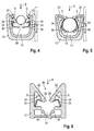
- FIGS. 4 and 5 illustrated embodiment of the fastening clip 10 differs from the embodiment according to the FIGS. 2 and 3 in that the webs 24 are not fastened to the frame 12, but to the support brackets 36. Furthermore, no protrusions 30 are provided.
- the webs 24 are formed in this embodiment, that they are stretched in the holding position of the pivot arms 22 substantially, but extend arcuate portions, the webs 24 abut in sections on the line 18 and hold them additionally in the receiving space 14 or fix.
- the line 18 is thus almost completely held by the support tabs 36, the webs 24 and the pivot arms 22 in the circumferential direction, so that the position of the line 18 in the receiving space 14 is reliably fixed.
- FIG. 6 embodiment shown also has no projections 30 and no contact surfaces 32, but only webs 24.
- the support tabs 36 are not provided on the side walls 28, but at the bottom 38 of the frame 12. The number and position of Abstützlaschen can However, be varied as desired to ensure the best possible fixation of the line 18 in the receiving space 14.
- fastening clips 10 with a plurality of receiving spaces 14 are possible, which are arranged side by side.
- Such an embodiment is in FIG. 7 shown, wherein two receiving spaces 14a, 14b are shown completely.
- the arrangement of the pivot arms 22a, the webs 24a, the projections 30a and the Abstützlaschen 36a corresponds in the first receiving space 14a substantially the structure of the mounting clips FIG. 2 ,
- the webs 24 here have two joints 34 and are fixed to the bottom 38 of the frame 12.
- the line 18 is enclosed in this receiving space 14b in the circumferential direction U of the webs 24 and fixed by them in the receiving space 14b
- the swivel arms 22a, 22b are shown in a preassembly position and in the assembly position (dashed lines), in which they are pivoted in the swivel direction S and the webs 24 are folded together.
- FIG. 9 the pivot arms 22a, 22b are shown in a holding position (dashed lines).
- the web 24b of the second receptacle 14b lies completely in the circumferential direction on the line 18, so that it is fixed by the web 24 in the receiving space 14b.
Landscapes
- Engineering & Computer Science (AREA)
- General Engineering & Computer Science (AREA)
- Mechanical Engineering (AREA)
- Architecture (AREA)
- Civil Engineering (AREA)
- Structural Engineering (AREA)
- Clamps And Clips (AREA)
- Supports For Pipes And Cables (AREA)
- Mutual Connection Of Rods And Tubes (AREA)
- Pivots And Pivotal Connections (AREA)
- Tents Or Canopies (AREA)
Applications Claiming Priority (1)
| Application Number | Priority Date | Filing Date | Title |
|---|---|---|---|
| FR1262817A FR3000536B1 (fr) | 2012-12-27 | 2012-12-27 | Clip de fixation |
Publications (1)
| Publication Number | Publication Date |
|---|---|
| EP2749801A1 true EP2749801A1 (fr) | 2014-07-02 |
Family
ID=48521065
Family Applications (1)
| Application Number | Title | Priority Date | Filing Date |
|---|---|---|---|
| EP13197669.8A Withdrawn EP2749801A1 (fr) | 2012-12-27 | 2013-12-17 | Clip de fixation |
Country Status (5)
| Country | Link |
|---|---|
| US (1) | US9016639B2 (fr) |
| EP (1) | EP2749801A1 (fr) |
| KR (1) | KR20140085363A (fr) |
| CN (1) | CN103899845B (fr) |
| FR (2) | FR3000536B1 (fr) |
Families Citing this family (17)
| Publication number | Priority date | Publication date | Assignee | Title |
|---|---|---|---|---|
| CN105026814B (zh) * | 2013-03-29 | 2018-02-09 | 伊利诺斯工具制品有限公司 | 管保持夹组件 |
| JP6169417B2 (ja) * | 2013-05-27 | 2017-07-26 | ナブテスコ株式会社 | 配線支持構造 |
| CN104500846B (zh) * | 2015-01-07 | 2016-05-25 | 芜湖南大汽车工业有限公司 | 一种汽车管件管夹结构 |
| US9903510B2 (en) * | 2015-11-03 | 2018-02-27 | Commscope Technologies Llc | Hanger for mounting cables |
| CN105633533A (zh) * | 2016-03-18 | 2016-06-01 | 江苏润杰通讯科技有限公司 | 一种腔体耦合器 |
| CN105633532A (zh) * | 2016-03-18 | 2016-06-01 | 江苏润杰通讯科技有限公司 | 一种腔体耦合器 |
| CN105633538A (zh) * | 2016-03-18 | 2016-06-01 | 江苏润杰通讯科技有限公司 | 一种腔体耦合器 |
| CN105633534A (zh) * | 2016-03-18 | 2016-06-01 | 江苏润杰通讯科技有限公司 | 一种腔体耦合器中的绝缘支撑定位板 |
| JP6839432B2 (ja) * | 2016-08-10 | 2021-03-10 | 竹内工業株式会社 | ケーブル保持具 |
| USD822476S1 (en) | 2016-10-26 | 2018-07-10 | Hellermanntyton Corporation | Multiple option clip |
| EP3658839A1 (fr) | 2017-07-26 | 2020-06-03 | Electrolux Appliances Aktiebolag | Appareil de refroidissement comprenant un élément de raccordement permettant de supporter des tubes ou des fils ou similaires |
| DE202017106320U1 (de) * | 2017-10-18 | 2017-10-25 | Igus Gmbh | Modulares Klemmsystem für Leitungen unterschiedlicher Durchmesser und Klemmteil hierfür |
| CN108131495B (zh) * | 2017-12-25 | 2020-11-10 | 伊利诺斯工具制品有限公司 | 导管保持夹组件 |
| CN108988214B (zh) * | 2018-07-30 | 2020-09-18 | 游精学 | 一种电缆拖拽保护器 |
| JP7491698B2 (ja) * | 2020-01-17 | 2024-05-28 | イリノイ トゥール ワークス インコーポレイティド | 円筒部品用クリップ組立体 |
| WO2021211316A1 (fr) | 2020-04-15 | 2021-10-21 | Illinois Tool Works Inc. | Dispositif de retenue de ligne |
| US11873929B2 (en) * | 2021-03-25 | 2024-01-16 | Illinois Tool Works Inc. | Multi-diameter clip |
Citations (5)
| Publication number | Priority date | Publication date | Assignee | Title |
|---|---|---|---|---|
| DE3215015A1 (de) * | 1982-04-22 | 1983-11-03 | Fa. A. Raymond, 7850 Lörrach | Halteclip aus hartelastischem kunststoff |
| EP1092903A1 (fr) * | 1999-10-16 | 2001-04-18 | fischerwerke Artur Fischer GmbH & Co. KG | Dispositif de fixation de tuyaux |
| US20040113041A1 (en) * | 2002-12-17 | 2004-06-17 | Dennis Hancock | Air cushioned grippers for article holders |
| US20040217236A1 (en) * | 2001-03-28 | 2004-11-04 | Tomio Shibuya | Vibration-proof clamp |
| DE202008007632U1 (de) * | 2008-06-06 | 2008-08-21 | Newfrey Llc, Newark | Befestigungselement zum Befestigen an einem Bolzen |
Family Cites Families (5)
| Publication number | Priority date | Publication date | Assignee | Title |
|---|---|---|---|---|
| US5851097A (en) * | 1997-06-03 | 1998-12-22 | Illinois Tool Works Inc. | Article with tethered prong fastener |
| US6554232B1 (en) * | 1999-11-04 | 2003-04-29 | International Truck Intellectual Property Company, L.L.C. | Tube clip |
| DE102005025679A1 (de) * | 2005-06-03 | 2006-12-07 | A. Raymond Et Cie | Vorrichtung zum Halten wenigstens eines länglichen Gegenstandes |
| US7188815B2 (en) * | 2005-06-03 | 2007-03-13 | Illnois Tool Works Inc | Fastener with tethered members |
| JP2008128328A (ja) * | 2006-11-20 | 2008-06-05 | Toyota Motor Corp | チューブクランプ |
-
2012
- 2012-12-27 FR FR1262817A patent/FR3000536B1/fr active Active
-
2013
- 2013-06-04 FR FR1355095A patent/FR3000537A1/fr active Pending
- 2013-12-16 US US14/107,000 patent/US9016639B2/en active Active
- 2013-12-17 EP EP13197669.8A patent/EP2749801A1/fr not_active Withdrawn
- 2013-12-27 CN CN201310740342.2A patent/CN103899845B/zh not_active Expired - Fee Related
- 2013-12-27 KR KR1020130164872A patent/KR20140085363A/ko not_active Ceased
Patent Citations (5)
| Publication number | Priority date | Publication date | Assignee | Title |
|---|---|---|---|---|
| DE3215015A1 (de) * | 1982-04-22 | 1983-11-03 | Fa. A. Raymond, 7850 Lörrach | Halteclip aus hartelastischem kunststoff |
| EP1092903A1 (fr) * | 1999-10-16 | 2001-04-18 | fischerwerke Artur Fischer GmbH & Co. KG | Dispositif de fixation de tuyaux |
| US20040217236A1 (en) * | 2001-03-28 | 2004-11-04 | Tomio Shibuya | Vibration-proof clamp |
| US20040113041A1 (en) * | 2002-12-17 | 2004-06-17 | Dennis Hancock | Air cushioned grippers for article holders |
| DE202008007632U1 (de) * | 2008-06-06 | 2008-08-21 | Newfrey Llc, Newark | Befestigungselement zum Befestigen an einem Bolzen |
Also Published As
| Publication number | Publication date |
|---|---|
| FR3000537A1 (fr) | 2014-07-04 |
| US20140201954A1 (en) | 2014-07-24 |
| FR3000536A1 (fr) | 2014-07-04 |
| FR3000536B1 (fr) | 2015-01-02 |
| CN103899845A (zh) | 2014-07-02 |
| KR20140085363A (ko) | 2014-07-07 |
| CN103899845B (zh) | 2018-02-09 |
| US9016639B2 (en) | 2015-04-28 |
Similar Documents
| Publication | Publication Date | Title |
|---|---|---|
| EP2749801A1 (fr) | Clip de fixation | |
| EP2110894B1 (fr) | Connecteur à fiche électrique et étrier de verrouillage destiné au verrouillage de deux éléments de boîtier électriques | |
| DE60301701T2 (de) | Klemme zum Halten von langgestrecktem Gegenstand | |
| DE102010032027B4 (de) | Schutz- und Führungsvorrichtung für ein Kabel oder dergleichen | |
| DE2740376C3 (de) | Elastische Klemmhalterung für Rundstäbe mit variablen Durchmessern | |
| DE3876421T2 (de) | Winkelfuehrung. | |
| EP2810829B1 (fr) | Clip de fixation | |
| WO2012072318A1 (fr) | Dispositif de fixation pour la fixation d'un câble | |
| WO2018204956A1 (fr) | Commande de meuble à moteur | |
| DE102007001223B4 (de) | Stromversorgungsvorrichtung für eine Schiebestruktur | |
| DE9411165U1 (de) | Spreizanker | |
| DE102008011672B4 (de) | Kabelführungsvorrichtung | |
| DE102006055368B4 (de) | Stromversorgungsanordnung für eine Schiebestruktur | |
| EP3586035B1 (fr) | Chaîne de guidage d'énergie et module à rouleaux | |
| DE102004061046B4 (de) | Gehäuse-Verschlußvorrichtung | |
| EP3757435B1 (fr) | Support pour objets allongés | |
| EP0695008B1 (fr) | Dispositif de blocage de câble universel | |
| DE102017214199B4 (de) | Anordnung und Verfahren zur Befestigung einer Endrohrblende | |
| WO2008092585A1 (fr) | Unité de fixation comprenant un élément de fixation pouvant être attaché au niveau d'un élément de support | |
| DE4400249C1 (de) | Wandinstallationskanal für Elektroinstallationseinrichtungen | |
| EP2852303A1 (fr) | Système de fixation et tiroir | |
| DE102023105023B3 (de) | Halteklammer | |
| DE102019112612B3 (de) | Halterahmen und Steckverbinder mit einem derartigen Halterahmen | |
| EP4019819A1 (fr) | Dispositif à deux composants, en particulier collier doté d'un anneau de collier | |
| EP3727091B1 (fr) | Arrangement comprenant une tringle et un element mural d'un tiroir |
Legal Events
| Date | Code | Title | Description |
|---|---|---|---|
| 17P | Request for examination filed |
Effective date: 20131217 |
|
| AK | Designated contracting states |
Kind code of ref document: A1 Designated state(s): AL AT BE BG CH CY CZ DE DK EE ES FI FR GB GR HR HU IE IS IT LI LT LU LV MC MK MT NL NO PL PT RO RS SE SI SK SM TR |
|
| AX | Request for extension of the european patent |
Extension state: BA ME |
|
| PUAI | Public reference made under article 153(3) epc to a published international application that has entered the european phase |
Free format text: ORIGINAL CODE: 0009012 |
|
| RIN1 | Information on inventor provided before grant (corrected) |
Inventor name: KUHM, MICHEL Inventor name: JACOTEY, JEREMY |
|
| R17P | Request for examination filed (corrected) |
Effective date: 20141105 |
|
| RBV | Designated contracting states (corrected) |
Designated state(s): AL AT BE BG CH CY CZ DE DK EE ES FI FR GB GR HR HU IE IS IT LI LT LU LV MC MK MT NL NO PL PT RO RS SE SI SK SM TR |
|
| 17Q | First examination report despatched |
Effective date: 20150413 |
|
| STAA | Information on the status of an ep patent application or granted ep patent |
Free format text: STATUS: THE APPLICATION IS DEEMED TO BE WITHDRAWN |
|
| 18D | Application deemed to be withdrawn |
Effective date: 20150824 |